Table of Contents
Advertisement
Advertisement
Table of Contents
Troubleshooting

Related Manuals for Stanley GT18


Summary of Contents for Stanley GT18
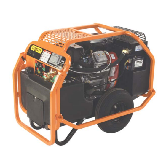
- Page 1 GT18 HYDRAULIC POWER UNIT WARNING AFETY PERATION AND AINTENANCE SERVICE MANUAL Stanley Hydraulic Tools 3810 SE Naef Road Milwaukie OR 97267-5698 503-659-5660 Copyright © 2005, The Stanley Works FAX 503-652-1780 SVCE/MAINT USA www.stanley-hydraulic-tools.com 65275 10/2005 Ver 2...
-
Page 3: Table Of Contents
REPAIRS AND / OR SERVICE TO THIS TOOL MUST ONLY BE DONE BY AN AUTHORIZED AND CERTIFIED DEALER. For the nearest authorized and certifi ed dealer, call Stanley Hydraulic Tools at the number listed on the back of this manual and ask for a Customer Service Representative. -
Page 4: Safety Symbols
SAFETY SYMBOLS Safety symbols and signal words, as shown below, are used to emphasize all operator, maintenance and repair actions which, if not strictly followed, could result in a life-threatening situation, bodily injury or damage to equip- ment. This is the safety alert symbol. It is used to alert you to potential personal injury hazards. -
Page 5: Safety Precautions
In addition to this manual, read and understand safety and operating instructions in the Engine Operation Manual furnished with the power unit. The GT18 Hydraulic Power Unit will provide safe and dependable service if operated in accordance with the instructions given in this manual. Read and understand this manual and any stickers and tags attached to the Power Unit. -
Page 6: Tool Stickers & Tags
TOOL STICKERS & TAGS 62302 Power Unit Dash Decal 62300 Single Circuit Decal DANGER CHOKE PULL TO START PUSH TO RUN 62302 DANGER CHOKE PULL TO START PUSH TO RUN AC 110V 1000W MAX CONTINUOUS 62318 POWERLINK™ Only 62300 62305 POWERLINK™ Only... -
Page 7: Hydraulic Hose Requirements
HOSE SAFETY TAGS To help ensure your safety, the following DANGER tags are attached to all hose purchased from Stanley Hydrau- lic Tools. DO NOT REMOVE THESE TAGS. -
Page 8: Htma Requirements
HTMA REQUIREMENTS TOOL CATEGORY HYDRAULIC SYSTEM REQUIREMENTS TYPE I TYPEII TYPEIII TYPE RR FLOW RATE 4-6 gpm 7-9 gpm 11-13 gpm 9-10.5 gpm (15-23 lpm) (26-34 lpm) (42-49 lpm) (34-40 lpm) TOOL OPERATING PRESSURE 2000 psi 2000 psi 2000 psi 2000 psi (at the power supply outlet) (138 bar) -
Page 9: Operation
1. ENGINE CRANKCASE OIL LEVEL growth that may occur in cool operating hydraulic circuits. These fl uids are recommended by Stanley. Other fl uids Always check the oil level before starting the engine. Make that meet or exceed the specifi cations of these fl uids may sure the oil level is at the FULL MARK on the dipstick. - Page 10 OPERATION selected so that additional fi ttings such as reducer or adapter CONTROL PANEL fi ttings are not required. If adapter fi ttings are used, they must be approved steel hy- draulic fi ttings meeting a minimum operating pressure rating RETURN PRESSURE of 2500 psi/172 bar.
- Page 11 OPERATION At times it may be neccessary to reset the controller. This CONTROLS could happen if a fault occurs in the controller. For ex- ample, excessive engine speed. If a fault does occur the This unit is equipped with an advanced proportional engine power unit will return to an idle and the operator will have control system.
- Page 12 OPERATION it is good practice to start the power unit with the AC Con- COLD WEATHER STARTUP trol Switch in the OFF position. The unit will however start with this switch in either the ON or OFF position. 1. Use the procedures described under "STARTUP" and then follow the procedure below.
-
Page 13: Routine Maintenance
ROUTINE MAINTENANCE the bottom of the container. Slowly pour the fl uid back into ENGINE MAINTENANCE the hydraulic tank, avoiding the water at the bottom of the container. Follow the maintenance schedule and general maintenance instructions in the engine maintenance and operation •... -
Page 14: Programmable Controller
FAULT CODES specifi cally for use with engines equipped with the Stanley controller. Stanley Hydraulic Tools The Stanley controller is capable of identifying certain fault recommends that an authorized and certifi ed dealer perform calibration of this unit. conditions and alerting the user to them. A fl ashing LED indicates the fault conditions. -
Page 15: Fault Codes
FAULT CODES ENGINE FLASH FAULT SHUT- CORRECTIVE ACTION CODE DOWN APECS unit not calibrated Calibrate APECS unit. Check parameter settings. Over speed criteria may be too sensitive. Check for electrical noise entering controller. Check wiring and connections. Engine speed excessive Check case ground. -
Page 16: Testing & Troubleshooting
1. Set the fl ow selector switch to the OFF (center) position. 2. Set the throttle control switch to AUTO-OFF position. 3. Connect the Stanley Circuit Tester across two hose ends (where the tool would normally be connected). 4. Fully open the tester restrictor valve (counterclockwise). -
Page 17: Troubleshooting
TROUBLESHOOTING PROBLEM CAUSE REMEDY Engine will not start. Flow selector switch not in the OFF Make sure the fl ow selector switch is in position. the OFF position when starting. Battery not connected. Attach battery cables, check wires. Weak battery. Test battery, charge or replace. -
Page 18: Specifi Cations
SPECIFICATIONS Engine: ............................18 hp Briggs / 20 hp Honda Capacity ..................One 5 gpm/19 lpm Circuit or One 8 gpm/30 lpm Circuit Length: ................................36 in. / 91.4 cm Width: ................................23 in: / 58.4 cm Height: ................................29.5 in. / 74.9cm Weight (Wet): Single Circuit Briggs ....................330 lbs / 149.6 kg Weight (Wet): Single Circuit Honda ....................348 lbs / 157.8 kg Fuel Tank Capacity: ............................ -
Page 19: Service
SERVICE 2. Remove hose (7, fi g. 3) from the manifold assembly, GENERAL again hydraulic oil will drain from this hose. Service instructions in this section are limited to parts and 3. Disconnect the wiring harness plugs from the pressure components other than the engine and hydraulic pump. - Page 20 SERVICE 1. To remove the engine, follow steps 1 through 4 under OPTION B "Fuel Tank Removal". Block up the unit to keep it from tipping over. 2. Disconnect the wiring harness (See Figure 4 & 4A, Wir- Remove the handle bumper (42, fi g. 1 Briggs) or (88 fi g. 1A ing Diagrams for the correct connections).
- Page 21 SERVICE 4. Reinstall in reverse order. CAUTION 5. Honda Only. Adjust screw (56, fi g. 1A) to prevent the choke cable from over-centering the choke linkage. Be sure the tapered cone surfaces of the bushing and blower hub are clean and CONTROLLER REMOVAL (see fi...
- Page 22 SERVICE 7. With the cooler and fi lter assembly removed, the cooler and fi lter assembly can be separated by removing the 3. Remove the 4 hex fl ange bolts (30, fi g. 1, 42, fi g. 1A) threaded union (18, fi g. 1 or 1A). under the fuel tank that hold it to the frame base weldment.
-
Page 23: Parts Lists & Illustrations
FIGURE 1. BRIGGS ENGINE ASSEMBLY... -
Page 24: Briggs Engine Parts List
FIGURE 1. BRIGGS ENGINE PARTS LIST Item Item Part No. Description Part No. Description 04134 Pump, Single 36150 Muffl er 07810 Fuel Cap 36151 Heat Shield 60920 Grommet 36152 Screw, Hex Washer 59078 Fuel Tank 59007 Briggs Engine 04303 Battery 56656 Coupling 60921... -
Page 25: Honda Engine Assembly (Fig. 1A)
FIGURE 1A. HONDA ENGINE ASSEMBLY... -
Page 26: Honda Engine Parts List
FIGURE 1A. HONDA ENGINE PARTS LIST Item Item Part No. Description Part No. Description 18893 Flang Nut, 3/8-16 65294 Muffler Kit 58976 Hex Flange Bolt, 3/8-16 62292 Hex Washer Head Screw 31240 Retaining Ring No Item 21318 Washer, 3/4 36918 Honda Engine 59083 Blower Housing... -
Page 27: Frame Parts (Fig. 2)
FIGURE 2. FRAME PARTS RECEPTACLE ASSY-64942 TO STARTER SOLENOID 12 VOLT ACCESSORY NOT EQUIPPED ON ALL MODELS. GROUND 25 Amp FUSE AVAILABLE AS AN ADD-ON BLACK * IF ADDING 12 VOLT ACCESSORY, CUT AWAY LABEL AND PUNCH THROUGH DASH PANEL 12-VOLT RECEPTACLE Item Part No. -
Page 28: Hoses, Fittings & Clamps (Fig. 3)
FIGURE 3. HOSES, FITTINGS & CLAMPS Item Part No. Description 59130 Manifold Assy, Single Circuit 59104 Hose Barb, 3/4 in. Hose x 3/4 in. Pipe 62199 Hose Clamp 350000 Elbow, 45° Straight Thread 02773 Adapter 58569 Elbow, 90° 58943 Hose 350104 Connector, Straight Thread 40364... -
Page 29: Wiring Diagram - Additional Wiring For Honda (Fig. 4)
FIGURE 4. ADDITONAL WIRING DIAGRAM FOR HONDA POWER UNITS ONLY TO ACTUATOR PLUG ON MAIN POWER UNIT WIRING HARNESS 62407 MAGNETO WIRE (SEE PHOTOS) 62180 ACTUATOR TO PICK-UP COIL (SEE PHOTOS) TO FUEL SHUT-OFF ON MAIN POWER UNIT WIRING HARNESS-62405 TO MAGNETO WIRE ON MAIN TO ENGINE KILL ON MAIN POWER UNIT WIRING HARNESS-62404... -
Page 30: Wiring Diagram - Powerlink™ (Fig. 4A)
FIGURE 4A. POWERLINK™ WIRING DIAGRAM ONLY SPECIFIC MODELS WITH BRIGGS & STRATTON ENGINES ARE EQUIPPED WITH THE POWER LINK FEATURE ADDITIONAL AC CONTROL SWITCH ON DASH PANEL GROUND TERMINAL PLUG TO MAIN POWER UNIT HARNESS HARNESS PART NUMBER 62335 TO INVERTER RELAY-62301 YELLOW BLUE... -
Page 31: Wiring Diagram - Main Power Unit
FIGURE 4B. MAIN POWER UNIT WIRING HARNESS HARNESS P/N-62293 THROTTLE CONTROL SWITCH (NOTE: PLUG BEHIND SWITCH WITH BLUE & YELLOW WIRES GOES TO SWITCH ON TOP) FLOW SELECTOR SWITCH HOUR METER DIRECTIONAL VALVE START SWITCH MANIFOLD ASSY BLACK TO STARTER PRESSURE SWITCH SOLENOID PLUG TO PRESSURE... -
Page 32: Warranty
fi rst retail purchaser, or for a period of 2 years from the shipping date from Stanley, whichever period expires fi rst, to be free of defects in material and/or workmanship at the time of delivery, and will, at its option, repair or replace any tool or part of a tool, or new part, which is found upon examination by a Stanley authorized service outlet or by Stanley’s factory in Milwaukie, Oregon to be DEFECTIVE IN MATERIAL AND/OR WORKMANSHIP. - Page 33 Stanley Hydraulic Tools 3810 SE Naef Road Milwaukie, Oregon 503-659-5660 / Fax 503-652-1780 www.stanley-hydraulic-tools.com...