
Related Manuals for Stanley GTR20B01


Summary of Contents for Stanley GTR20B01
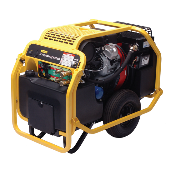
- Page 1 GTR20B01 HYDRAULIC POWER UNIT USER MANUAL Safety, Operation and Maintenance © 2014 Stanley Black & Decker, Inc. New Britain, CT 06053 U.S.A. 72784 2/2015 Ver. 8...
- Page 2 Disposizioni speciali: Misurazioni Representative in the Union: Patrick Vervier, Stanley Dubuis 17-19, rue Jules Berthonneau-BP 3406 41034 Blois Cedex, France. Vertreter in der Union/Représentant dans l’union/Representante en la Union/Rappresentante presso l’Unione Done at/Ort/Fait à/Dado en/Fatto a Stanley Hydraulic Tools, Milwaukie, Oregon USA...
-
Page 3: Table Of Contents
REPAIRS AND / OR SERVICE TO THIS TOOL MUST ONLY BE DONE BY AN AUTHORIZED AND CERTIFIED DEALER. For the nearest authorized and certified dealer, call Stanley Hydraulic Tools at the number listed on the back of this manual and ask for a Customer Service Representative. -
Page 4: Safety Symbols
Always observe safety symbols. They are included for your safety and for the protection of the tool. LOCAL SAFETY REGULATIONS Enter any local safety regulations here. Keep these instructions in an area accessible to the operator and mainte- nance personnel. 4 ► GTR20B01 User Manual... -
Page 5: Safety Precautions
• Always keep critical tool markings, such as labels and warning stickers legible. • To avoid personal injury or equipment damage, all tool repair, maintenance and service must only be performed by autho- rized and properly trained personnel. GTR20B01 User Manual ◄ 5... -
Page 6: Tool Stickers
Dual Circuit CE Decal 73306 Lift Point Decal 59126 DASH RR DECAL 14-16 LPM 15Lpm at 138bar EHTMA CATEGORY 27-33 LPM 30Lpm at 138bar EHTMA CATEGORY 14-16 LPM 15Lpm at 138bar EHTMA CATEGORY 72783 DUAL CIRCUIT CE CECAL 6 ► GTR20B01 User Manual... -
Page 7: Hydraulic Hose Requirements
HOSE SAFETY TAGS To help ensure your safety, the following DANGER tags are attached to all hose purchased from Stanley Hydraulic Tools. DO NOT REMOVE THESE TAGS. -
Page 8: Hose Recommendations
HOSE RECOMMENDATIONS 8 ► GTR20B01 User Manual... -
Page 9: Ehtma/Htma Requirements
2000 psi 2000 psi 2000 psi (at the power supply outlet) (172 bar) (138 bar) (138 bar) (138 bar) (138 bar) NOTE: These are general hydraulic system requirements. See tool specification page for tool specific requirements GTR20B01 User Manual ◄ 9... -
Page 10: Operation
The 2 right female quick disconnect fittings are the RE- TURN FLUID IN fittings. QUICK DISCONNECT COUPLERS H.T.M.A. approved quick disconnect couplings are in- stalled to hydraulic hoses so that the direction of oil flow is always 10 ► GTR20B01 User Manual... - Page 11 ON or -8 SAE O-Ring (P/N 00936) RUN position, this could drain the battery. Make sure the ignition switch is returned to the OFF position. PRESSURE PRESSURE RETURN RETURN Figure 2. Hydraulic Connections GTR20B01 User Manual ◄ 11...
- Page 12 Connect hoses and the tool as desrcribed on pages 9 When the throttle control switch is in the "AUTO-OFF" and 10. position, the engine speed is held to maintain 4 gpm/15 lpm or 8 gpm/30 lpm depending on which position the 12 ► GTR20B01 User Manual...
- Page 13 50°F/10°C. 3. If the tools and tool hoses are cold, it is recom- mended to allow hydraulic fluid to circulate through the tool hoses until warm before using the tool. GTR20B01 User Manual ◄ 13...
-
Page 14: Routine Maintenance
Do not use your hand to perform this check. • Change the hydraulic filter element every 200 hours of operation. Change more often if cold, moist or dusty conditions exist. • Check oil cooler for debris. Remove debris with air pressure. 14 ► GTR20B01 User Manual... -
Page 15: Programmable Controller
A flashing LED indicates FAULT CODES the fault condition The Stanley controller is capable of identifying certain fault conditions and alerting the user to them. A flash- ing LED indicates the fault conditions. The current fault code list is shown on the following page. Please note the following: 1. -
Page 16: Fault Codes
Auxiliary output #2 is shorted Check the lamp or relay hooked to the output. If fault is still present, consult factory. Actuator disconnected or Check actuator wiring and actuator resistance. open circuit Resistance should be less than 10 ohms. 16 ► GTR20B01 User Manual... -
Page 17: Testing & Troubleshooting
1. Set the flow selector switches to the OFF (center) po- sition. 2. Set the throttle control switch to AUTO-OFF position. 3. Connect the Stanley Circuit Tester across two hose ends (where the tool would normally be connected). 4. Fully open the tester restrictor valve (counterclock- wise). -
Page 18: Troubleshooting
Adjust or replace valve. Suction hose kinked. Make sure suction hose from fluid reservoir to pump inlet has a smooth curve. Solenoid not working. Check solenoid operation and electrical connections. Tool is defective. Refer to tool manual. 18 ► GTR20B01 User Manual... -
Page 19: Specifications
The power unit is clearly marked with these E.H.T.M.A. categories. It is important that any work tool used with the power unit is of a compatible category. If in any doubt, consult your Stanley Hydraulic Tool dealer. GTR20B01 User Manual ◄ 19... -
Page 20: Accessories
POWER UNITS,TRACHORSE & GAS/FUEL DRIVEN EQUIPMENT: A1. Federal Emission Component Compliance 40CFR part 1060.120 Stanley warrants all fuel system emission com- ponents for 2 years from the date of original purchase provided there has been no abuse, neglect, modifi cations, or improper maintenance. -
Page 21: Gtr20B01 Illustration
GTR20B01 PARTS ILLUSTRATION (FIG 1) GTR20B01 User Manual ◄ 21... -
Page 22: Gtr20B01 Parts List
GTR20B01 PARTS LIST (FIG 1) ITEM DESCRIPTION ITEM DESCRIPTION 21318 Washer, 3/4 36150 Muffler 59083 Blower Housing 36151 Heat Shield 56655 Pump Mount 36152 Screw, Hex Washer 60919 Fuel Elbow 59007 Briggs Engine (Includes 62385 Stud Items 60 thru 70) - Page 23 62269 Frame Weldment 23530 Hex Flange Bolt, 3/8 in. -16 58916 Handle Lock 62268 Lift Handle 59079 Cooler Guard 59095 Flange Nut, 1/4 in. -20 59127 Shuttle Check Valve 350041 Hollow Hex Plug 4 SAE GTR20B01 User Manual ◄ 23...
-
Page 24: Fuel Tank & Cap
FUEL TANK & CAP NOTE: When ordering a fuel tank (item 37) or fuel tank cap (item 35) DO NOT MIX OLD STYLE TANK AND CAP WITH NEW STYLE TANK AND CAP. If you have a power unit and it was purchased prior to 2011 and need to replace the fuel tank or fuel tank cap, you must purchase the same tank and cap that came with your unit. -
Page 25: Hoses, Fittings & Clamps
Elbow, 45° Straight Thread 350000 02773 Adapter 58569 Elbow, 90° 58943 Hose Connector, Straight Thread 350104 40364 Elbow, 45° 59089 Hose, Return Briggs Engine 59089 Hose, Suction 59105 Hose Barb, 3/4 in. Hose x 3/4 in. Pipe GTR20B01 User Manual ◄ 25... -
Page 26: Main Wiring Harness
MAIN WIRING HARNESS HARNESS PART NUMBER 62294 RED WIRE TO POSITIVE "+" TOOL CIRCUIT 1 SIDE HOUR METER SWITCH 2 WHITES “+” BLACK WIRE TO NEGATIVE “-” MULTI COLORS SIDE HOUR METER PLUG TO ROTARY START SWITCH TOOL CIRCUIT 1 SOLENOID AUTO IDLE BLUE/BLACK... -
Page 27: Dual Circuit Wire Harness
DIODE (RED WIRE) CIRCUIT 2 SWITCH (YELLOW, WHITE, BLUE, GREEN) STARTER SWITCH CIRCUIT 1 SWITCH STARTER POST (RED WIRE) STARTER SOLENOID ENGINE KILL (LIGHT GREEN WIRE) (BLACK WIRE) RECTIFIER (WHITE WIRE) FUEL SHUTOFF (RED WIRE) GTR20B01 User Manual ◄ 27... - Page 28 Stanley Hydraulic Tools 3810 SE Naef Road Milwaukie, Oregon 97267-5698 USA (503) 659-5660 / Fax (503) 652-1780 www.stanleyhydraulics.com...