
Related Manuals for Stanley GPV13


Summary of Contents for Stanley GPV13
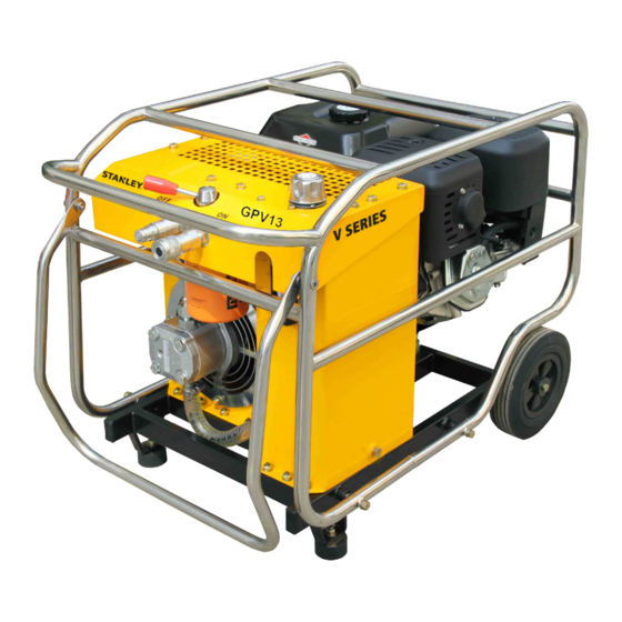
- Page 1 GPV13 V SERIES HYDRAULIC POWER UNIT USER MANUAL Safety, Operation and Maintenance 73417 1/2014 Ver. 1...
- Page 2 2 ► GPV13 User Manual...
-
Page 3: Table Of Contents
REPAIRS AND / OR SERVICE TO THIS TOOL MUST ONLY BE DONE BY AN AUTHORIZED AND CERTIFIED DEALER. For the nearest authorized and certified dealer, call Stanley Hydraulic Tools at (503-659-5660) and ask for a Cus- tomer Service Representative. GPV13 User Manual ◄ 3... -
Page 4: Safety Symbols
Always observe safety symbols. They are included for your safety and for the protection of the tool. LOCAL SAFETY REGULATIONS Enter any local safety regulations here. Keep these instructions in an area accessible to the operator and mainte- nance personnel. 4 ► GPV13 User Manual... -
Page 5: Safety Precautions
• Do not operate the power unit if gasoline odor is present. The GPV13 Hydraulic Power Unit will provide safe and dependable service if operated in accordance with the • Do not use flammable solvents around the power instructions given in this manual. -
Page 6: Tool Stickers & Tags
TOOL STICKERS & TAGS Hydraulic GPV13 Power Pack Safety Tag wire tied to power unit 6 ► GPV13 User Manual... -
Page 7: Hose Types
HOSE SAFETY TAGS To help ensure your safety, the following DANGER tags are attached to all hose purchased from Stanley Hydraulic tools. DO NOT REMOVE THESE TAGS. -
Page 8: Hose Recommendations
HOSE RECOMMENDATIONS 8 ► GPV13 User Manual... -
Page 9: Htma Requirements
2000 psi 2000 psi 2000 psi (at the power supply outlet) (172 bar) (138 bar) (138 bar) (138 bar) (138 bar) NOTE: These are general hydraulic system requirements. See tool specification page for tool specific requirements GPV13 User Manual ◄ 9... -
Page 10: Operation
These fluids are recommended by Stanley Hy- as reducer or adapter fittings are not required. draulic Tools. Other fluids that meet or exceed the speci- If adapter fittings are used, they must be approved steel fications of these fluids may also be used. -
Page 11: Figure 3. Hydraulic Connections
HTMA 1/2 INCH MALE not being used move the lever to the idle position. QUICK DISCONNECT COUPLER ADAPTER, 3/8 INCH MALE PIPE × -8 SAE O-RING PRESSURE RETURN TOOL Briggs Throttle Control Lever Figure 3. Hydraulic Connections GPV13 User Manual ◄ 11... - Page 12 Do not remove the fuel cap while the engine is running. Do not add fuel to the tank while the engine is hot. Do not fill the fuel tank to a point of overflowing. 12 ► GPV13 User Manual...
-
Page 13: Figure 6. Choke Lever
OFF position. Figure 7. Fuel Lever Honda 7. Position the engine ON-OFF switch to the ON posi- tion as shown in Figure 8, see figure 5 for Briggs on/ off switch location. GPV13 User Manual ◄ 13... -
Page 14: Maintenance
Change the hydraulic filter element every 100 hours of operation or 6 months which ever comes first. Change more often if cold, moist or dusty conditions exist. • Check oil cooler for debris. Remove debris with air pressure. 14 ► GPV13 User Manual... -
Page 15: Maintenance Schedule
These items should be serviced by an authorized Honda dealer, unless the owner has the proper tools and is mechanically proficient. See the Honda Shop Manual. For additional maintenance information see the Honda engine operator’s manual that was supplied with the power unit. GPV13 User Manual ◄ 15... - Page 16 Hyd Fluid Cooler (Inspect & Clean as necessary) Every 50 hours Service more frequently when used in dusty areas. NOTE: (1) For additional maintenance information see the Briggs & Stratton engine operator’s manual that was supplied with the power unit. 16 ► GPV13 User Manual...
-
Page 17: Testing & Troubleshooting
1. Set the throttle control lever to the far left or full throt- tle position. c. Tighten the nut and retest. 2. Connect the Stanley Circuit Tester across the hose ends (where the tool would normally be connected). 3. Fully open the tester restrictor valve (counterclock- wise). -
Page 18: Troubleshooting
Keep hands clear of rotating objects. Relief valve stuck open. Adjust or replace valve. Suction hose kinked. Make sure suction hose from fluid reservoir to pump inlet has a smooth curve. Tool is defective. Refer to tool manual. 18 ► GPV13 User Manual... -
Page 19: Specifications
Category (GPV138B02)......................Type II, EHTMA Class D Flow Rate ........................ 20 lpm/5 gpm or 30 lpm/8 gpm Nominal Pressure .......................... 103 bar/1500 psi Max Pressure ..........................155 bar/2250 psi Sound Power Level ............................101 Lwa Vibration Level ............................... N/A GPV13 User Manual ◄ 19... - Page 20 Hefei INTACA Science-Technology Development Co.,Ltd. Add: A-7 Building Gongtou-Liheng Industry Square, Western Section Fanhua Street(the Cross Wenshan Road),Hefei,Anhui,China Tel:0551-63498781/2/3 Fax:0551-63498780 P.C.:230601 http: //www.intaca.cn...