Table of Contents
Advertisement
Advertisement
Table of Contents

Related Manuals for Jet JWBS-10OS


Summary of Contents for Jet JWBS-10OS
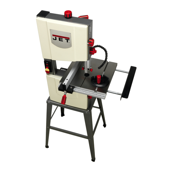
- Page 1 Operating Instructions and Parts Manual 10-inch Band Saw Model JWBS-10OS 162920 WALTER MEIER (Manufacturing) Inc. 427 New Sanford Road LaVergne, Tennessee 37086 Part No. M-707200 Ph.: 800-274-6848 Revision A2 02/2012 www.waltermeier.com Copyright © 2012 Walter Meier (Manufacturing) Inc.
-
Page 2: Warranty And Service
Walter Meier is consistently adding new products to the line. For complete, up-to-date product information, check with your local Walter Meier distributor, or visit waltermeier.com. WARRANTY JET products carry a limited warranty which varies in duration based upon the product (MW stands for Metalworking, WW stands for Woodworking). WHAT IS COVERED? This warranty covers any defects in workmanship or materials subject to the exceptions stated below. -
Page 3: Table Of Contents
Table of Contents Warranty and Service ............................2 Table of Contents ..............................3 Warning ................................4 Introduction ................................6 Specifications ..............................6 Features ................................6 Shipping Contents ............................... 7 Contents of Shipping Container ........................7 Contents of Hardware Bag ..........................7 Assembly ................................ -
Page 4: Warning
Warning 1. Read and understand the entire owner's manual before attempting assembly or operation. 2. Read and understand the warnings posted on the machine and in this manual. Failure to comply with all of these warnings may cause serious injury. 3. -
Page 5: Save These Instructions
20. Make your workshop child proof with padlocks, master switches or by removing starter keys. 21. Give your work undivided attention. Looking around, carrying on a conversation and “horse-play” are careless acts that can result in serious injury. 22. Maintain a balanced stance at all times so that you do not fall or lean against the blade or other moving parts. Do not overreach or use excessive force to perform any machine operation. -
Page 6: Introduction
This manual is provided by Walter Meier (Manufacturing) Inc., covering the safe operation and maintenance procedures for the JET model JWBS-10OS band saw. This manual contains instructions on installation, safety precautions, general operating procedures, maintenance instructions and parts breakdown. This machine has been designed and constructed to provide years of trouble free operation if used in accordance with instructions set forth in this manual. -
Page 7: Shipping Contents
Shipping Contents Remove all contents from the shipping carton. Do not discard the carton or packing material until the band saw is assembled and is running satisfac- torily. Compare the contents of the carton against the list of parts in Contents of Shipping Container (below). The letter identification in the list corresponds to the items shown at right. -
Page 8: Assembly
Assembly Back Front Figure 1 Stand 8. Tighten all nuts with a 13mm socket or wrench. Referring to Figure 1: Table Installation 1. Place the band saw (A) on its back as shown above, either on the floor or Referring to Figure 3: preferably on a workbench. -
Page 9: º Table Stop
90º Table Stop Referring to Figure 4: 1. Slighty loosen the lock knob (C ) and tilt the table (C) up as shown. 2. Thread the M6 hex nut (T) approximately half way onto the M6x32 hex cap screw (O). Then thread the screw half way into the threaded mounting hole (C ) underneath the table. -
Page 10: Adjustments
Adjustments Unplug the machine from the power source before making any repairs or adjustments. Failure to comply may cause serious injury. Tilting the Table Referring to Figure 7: 1. Loosen the lock knob (A). Figure 7 2. Tilt table (C) up to 50 degrees maximum to the right or down 5 degrees to the left. -
Page 11: Changing Blades
Changing Blades the width of the blade. 4. Set the blade tension with knob (T) to corres-pond Blade teeth are sharp! Use care to the blade width as marked on the gauge (X). when handling the saw blade. Failure to comply Note: A meter is recommended to precisely set may cause serious injury. -
Page 12: Upper Blade Guide Positioning
Upper Blade Guide Positioning Referring to Figure 11: The upper blade guide assembly (C) should be adjusted to just above the material being cut. To adjust: Loosen lock knob (B) and raise or lower the upper blade guide assembly (C) by turning the height adjustment knob (A). -
Page 13: Operating Controls
Loosen the hex cap screw (G, not visible) with a 10mm wrench and adjust the entire assembly back or forth to just clear the back of the saw blade. Tighten screw (G), then fine tune the adjustment by repeating the first part of this step. -
Page 14: Replacing The Poly V-Belt
Replacing the Poly V-Belt Adjusting Poly V-Belt Tension Disconnect machine from the Disconnect machine from the power source! Never make adjustments with power source! Never make adjustments with the machine running! Failure to comply may the machine running! Failure to comply may cause serious injury! cause serious injury! 1. -
Page 15: Grounding Instructions
(Figure 11), if a properly grounded outlet is not Grounding Instructions available. The temporary adapter should only be used until a properly grounded outlet can be General Information installed by a qualified electrician. This adapter is not applicable in Canada. The green colored This Band Saw must be rigid ear, lug, or tab, extending from the adapter, grounded while in use to protect the operator... -
Page 16: Troubleshooting
Troubleshooting Trouble Probable Cause Remedy Saw unplugged Check plug connections Saw stops or will not Fuse blown, or circuit breaker tripped Replace fuse, or reset circuit breaker start Cord damaged Replace cord Check blade with square and adjust stop (see Adjusting Table Stop on Stop not adjusted correctly Does not make page 10). -
Page 17: Optional Accessories
Optional Accessories 10" Band Saw Blades Stock No. Application Length Width Thickness 707201 Scrollwork 67.5” 0.125” 0.025” 18TR 707202 Resaw 67.5” 0.5” 0.032” 707203 General Purpose 67.5” 0.5” 0.025” 707204 General Purpose 67.5” 0.25” 0.025”... -
Page 18: Parts
4 ....JWBS10OS-4 ..Lower Door .................... 1 5 ....JWBS10OS-5 ..Rivet ..............2.5x5 ......4 6 ....JWBS10OS-6 ..JET Nameplate ..................1 7 ....JWBS10OS-7 ..Upper Door .................... 1 8 ....JWBS10OS-8 ..Blade ............67.5 x .375 x .014, 6TPI ..1 9 .... - Page 19 Index No. Part No. Description Size 48 ..... JWBS10OS-48..Self-Tapping Screw ..........ST2.2x6.5 ....1 49 ..... JWBS10OS-49..Sliding Plate ..................1 50 ..... JWBS10OS-50..Guide Block ................... 2 51 ..... JWBS10OS-51..Self-Tapping Screw ..........ST4.2x13 ....4 52 ..... TS-1482021 .....Hex Cap Screw ..........M6x12 ...... 11 53 .....
- Page 20 Index No. Part No. Description Size 107 ... JWBS10OS-107..External Tooth Lock Washer .......M6 ......4 108 ... JWBS10OS-108..Support Bracket ..................1 109 ... JWBS10OS-109..Knob ..................... 1 110 ... JWBS10OS-110..Carriage Bolt ............M6x16 ......4 111 ... TS-1505011 .....Socket Head Cap Screw ........M10x16 ...... 2 112 ...
-
Page 21: Assembly Drawing
Assembly Drawing... -
Page 22: Electrical Connections
Electrical Connections 1/2HP, 1PH, 115V Band Saw Model No.: JWBS-10Os wiring diagram-RBS230C.jpg (1584x1223x16M jpeg) - Page 24 WALTER MEIER (Manufacturing) Inc. 427 New Sanford Road LaVergne, Tennessee 37086 Phone: 800-274-6848 www.waltermeier.com...