Table of Contents
Advertisement
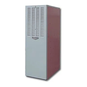
GAS FIRED HIGH EFFICIENCY FURNACE
DOWN FLOW & DIRECT VENT (SEALED COMBUSTION)
MODEL: CMA1-50N & CMA2-75N
INSTALLATION AND SERVICE MANUAL
For installation in:
1. Manufactured Homes
2. Modular Homes/Buildings
3. Site Constructed—Residential (Single Story Dwellings)
Do not store or use gasoline or other flammable vapors and liquids in the vicinity of this
or any other appliance.
• Do not try to light any appliance.
• Do not touch any electrical switch; do not use any phone in your building.
• Immediately call your gas supplier from a neighbor's phone.
Follow the gas supplier's instructions.
• If you cannot reach your gas supplier, call the fire department.
:
If the information in these instructions is not followed exactly, a fire or explosion may
result causing property damage, personal injury, or loss of life.
: Improper installation, adjustment, alteration, service, or maintenance can cause
injury or property damage. Refer to this manual. For assistance or additional information,
consult a qualified installer, service agency, or fuel supplier.
: Do not use this appliance if any part has been underwater. Immediately call a
qualified service technician to inspect the appliance and to replace any part of the electrical or
control system that has been underwater.
PLEASE READ THESE INSTRUCTIONS PRIOR TO INSTALLATION, INITIAL FIRING, AND BEFORE
PERFORMING ANY SERVICE OR MAINTENANCE. THESE INSTRUCTIONS MUST BE LEFT WITH THE USER
AND SHOULD BE RETAINED FOR FUTURE REFERENCE BY QUALIFIED SERVICE PERSONNEL.
MG-508
ECN 5135-MA 100615
FOR YOUR SAFETY
WHAT TO DO IF YOU SMELL GAS
THERMO PRODUCTS, LLC.
POST OFFICE BOX 217
NORTH JUDSON, IN 46366
PHONE: (574) 896-2133
MADE IN USA
Advertisement
Table of Contents

Related Manuals for Thermo Pride CMA1-50N


Summary of Contents for Thermo Pride CMA1-50N
-
Page 1: For Your Safety
GAS FIRED HIGH EFFICIENCY FURNACE DOWN FLOW & DIRECT VENT (SEALED COMBUSTION) MODEL: CMA1-50N & CMA2-75N INSTALLATION AND SERVICE MANUAL For installation in: 1. Manufactured Homes 2. Modular Homes/Buildings 3. Site Constructed—Residential (Single Story Dwellings) FOR YOUR SAFETY Do not store or use gasoline or other flammable vapors and liquids in the vicinity of this or any other appliance. -
Page 2: Table Of Contents
TABLE OF CONTENTS SECTION BEGINNING PAGE SAFETY INFORMATION FURNACE SPECIFICATIONS III. GENERAL INSTRUCTIONS AND CLEARANCES IV. GENERAL INSTALLATION A. FURNACE LOCATION B. BASE INSTALLATION C. ALCOVE INSTALLATION D. CLOSET INSTALLATION E. FUEL PIPING F. GENERAL VENTING REQUIREMENTS G. CONNECTING THE EXHAUST VENT, AND COMBUSTION AIR INTAKE H. -
Page 3: Safety Information
All installations and services must be performed by qualified service personnel. I. SAFETY INFORMATION This and the following page contain reproductions of the various warning and instruction labels placed on the Thermo Pride Condensing Gas Furnaces. Please read and comply with the contents of these labels. - Page 4 All installations and services must be performed by qualified service personnel. This and the previous page contain reproductions of the various safety and instruction labels placed on the Thermo Pride Condensing Gas Furnaces. Please read and comply with the contents of these labels.
- Page 5 Section IV. The following pages contain various warnings and cautions found throughout the Thermo Pride Gas Fired High Efficiency Furnace Manual. Please read and comply with the statements below. : This furnace is not to be used for temporary heating of buildings or structures under construction.
- Page 6 All installations and services must be performed by qualified service personnel. The vent and air intake elbows must be kept away from bushes, shrubs or any vegetation that may restrict the flow of flue products. It must also be kept clear of any leaves, weeds or other combustible materials. Keep the vent hood clear of snow.
- Page 7 All installations and services must be performed by qualified service personnel. : Copper and brass tubing and fittings (except tin lined) shall not be used if the gas contains more than a trace (0.3 grains per 100 cubic ft.) of hydrogen sulfide gas.
-
Page 8: Furnace Specifications
All installations and services must be performed by qualified service personnel. II. FURNACE SPECIFICATIONS - CMA SERIES MODEL CMA1-50 CMA2-75 INPUT IN BTUH 50,000 75,000 OUTPUT IN BTUH 48,000 72,000 MAIN ORIFICE-NAT. MAIN ORIFICE-LP 1.5 mm GAS SUPPLY PRESSURE L.P. MINIMUM 11”... -
Page 9: General Instructions And Clearances
All installations and services must be performed by qualified service personnel. INSTALLATION PARTS PACKAGE CMA*-50 CMA*-75 PARTS PKG# S00S4179 S00S4114 DESCRIPTION PART # PART # J-box cover 350020 350020 wire nut 300132 300132 3" stainless steel hose clamp 300276 300276 2-3/8"... - Page 10 All installations and services must be performed by qualified service personnel. accordance with the latest edition of the UL Standard for Single and Multiple Station Carbon Monoxide Alarms, UL 2034, or the CSA International Standard, Residential Carbon Monoxide Alarming Devises, CSA 6.19. 5.
-
Page 11: General Installation
All installations and services must be performed by qualified service personnel. MODELS CMA CLOSET ALCOVE FRONT 6” 18” BACK 0” 0” SIDES 0” 0” VENT CONNECTOR(PVC) 0” 0” 0” 0” PLENUM SIDES 1” 1” TOP AND SIDES OF DUCT 1” 1”... - Page 12 All installations and services must be performed by qualified service personnel. Combustible Floor Base Model: 70-BASE Figure 1A. Coil Cabinet Model: CE113S Note: This cabinet cannot be utilized as a cottage base. Figure 1B.
- Page 13 All installations and services must be performed by qualified service personnel. Cottage Base Model: 01COT-BASE Figure 1C. NOTE: Serves as a plenum for single story applications with exposed supply air systems.
-
Page 14: Base Installation
All installations and services must be performed by qualified service personnel. B. BASE INSTALLATION 1. Combustible Floor Base Model: 70 BASE Use the base bottom panel as a template to mark floor opening locations (see Figure 2). Cut a square opening in the floor for the supply air connector duct. Cut the opening 1-inch larger than the square template opening. -
Page 15: Alcove Installation
All installations and services must be performed by qualified service personnel. connector duct. Remove the bottom panel. Cut an opening in the distribution duct slightly larger than the connector duct. (refer to Figure 2 for location of this cut.) Cut the connector duct to length. Install the connector duct. Bend over each tab. Insure an airtight seal by using high temperature sealant or tape on the joint. -
Page 16: Closet Installation
All installations and services must be performed by qualified service personnel. D. CLOSET INSTALLATION 1. The return air opening into the closet is to have a minimum free area of 250 sq. in. (see Figure 5). 2. The return air opening may be located in the top, center or (ideally) bottom of the closet door or side wall. -
Page 17: Fuel Piping
All installations and services must be performed by qualified service personnel. E. FUEL PIPING Sizing and installation of fuel lines must be in accordance with Federal, State & Local regulations. Including the National Fuel Gas Code NFPA 54/ANSI-Z233.1 (Latest Edition). NOTE: These furnaces are designed to be gas piped through the left side or the bottom. -
Page 18: General Venting Requirements
All installations and services must be performed by qualified service personnel. The furnace and its gas valve must be disconnected from the gas supply during pressure testing of the gas supply system at pressures in excess of 1/2 PSIG or 14 inches w.c F. - Page 19 All installations and services must be performed by qualified service personnel. MAXIMUM VENT LENGTH VENT SIZE 2 IN. PVC FURNACE VENT EXHAUST COMBUSTION AIR INTAKE MODEL LENGTH VENT ELBOWS (NO.) (FT.) ELBOWS (NO.) *Note the drain elbow supplied with CMA furnaces count as 1 elbow. **Note the two 45°...
-
Page 20: Connecting The Exhaust Vent And Combustion Air Intake
All installations and services must be performed by qualified service personnel. G. CONNECTING THE EXHAUST VENT AND COMBUSTION AIR INTAKE Figure 6. shows the typical exhaust vent and combustion air intake connection for CMA furnace. Figure 6. (CMA*-75 SHOWN) NOTICE: The exhaust vent pipe must be supported every 4 feet. After making sure the length of the piping is correct glue all connections in place. -
Page 21: Direct Venting Through A Sidewall
All installations and services must be performed by qualified service personnel. NOTICE: The furnace model series CMA may be vented either through the sidewall or the roof. For sidewall instructions, continue to the following section. For roof venting, refer to Section IV J, of this manual. NOTICE: The air intake pipe must be supported every 4 feet. - Page 22 All installations and services must be performed by qualified service personnel. Figure 7: Proper Direct Vent Terminations (RH & LH views) and Vent Termination Only w/o Outside Combustion Air Intake (RH view) NOTICE: If exterior sidewall building materials are subject to degradation from contact with flue gases or moisture, a minimum 24-inch diameter shield shall be fabricated from stainless steel or UV-resistant plastic sheet.
- Page 23 All installations and services must be performed by qualified service personnel. Figure 8: Typical Relative Locations of Direct Vent Terminations When Sidewall Venting 3. Exhaust Vent Terminal Location Clearance Requirements a. The vent terminal shall be located at least 3-feet above any forced air inlet located within 10-feet.
- Page 24 All installations and services must be performed by qualified service personnel. Figure 9: NFGC Minimum Clearances Between the Vent Terminal and Various Building Features...
-
Page 25: Installation Of Outside Exhaust/Intake Terminations
All installations and services must be performed by qualified service personnel. 4. Vent Terminal Location Guidelines : Bushes, shrubs, or any vegetation that may restrict the flow of flue products must be kept away from vent and air intake terminations. Terminations must also be kept clear of any leaves, weeds, combustible materials, snow, and ice build-up. - Page 26 All installations and services must be performed by qualified service personnel. inlet as shown in Figure 10, making sure that the spacing between the inlet and outlet complies with that noted in Figure 8. Figure 10: Typical Construction Details of Sidewall Vent and Air Intake Terminations 3.
- Page 27 All installations and services must be performed by qualified service personnel. 3. Place second flashing plate on roof over existing hole. 4. Plate must be sealed to roof to ensure a weather proof seal. 5. Secure plate to roof. 6. Drop pvc pipes thru holes in flashing plates. 7.
-
Page 28: Condensate Drain Line And Trap Assembly
All installations and services must be performed by qualified service personnel. When the PVC vent and combustion air intake pipes pass through a ceiling, and a fire stop is required. Refer to the following: CEILING: Frame out area around where PVC pipe is to penetrate ceiling. Cut a 2-3/8”... -
Page 29: Electrical Wiring
All installations and services must be performed by qualified service personnel. 3. An optional condensate pump (P/N 350225) is available. This pump will not fit into the vestibule of the furnace and must be installed below the furnace for operation. Instructions will be included with pump if this option is utilized. Figure 14. - Page 30 All installations and services must be performed by qualified service personnel. NOTE: Class 1 thermostat wire must be used inside the furnace burner compartment. a. Insert 24 VAC wires through the plastic grommet on the left side of the furnace casing. b.
- Page 31 All installations and services must be performed by qualified service personnel. mounted junction box. The hot leg must pass through the disconnect switch in all cases to prevent the hazard of electrical shock when servicing. IMPORTANT: The furnace must be grounded in accordance with local codes and with the National Electrical Code, ANSI/NFPA NO.
- Page 32 All installations and services must be performed by qualified service personnel. CMA1-50 ALTERATIONS REQ’D FOR A/C @ DESIGN EXTERNAL STATIC PRESSURE COOLING UNIT HTG Speed Recommended CLG Speed 24,000 MED-LOW 30,000 MED-HIGH 36,000 HIGH Furnace Airflow (CFM) vs. External Static pressure (in. WC.) Speed Tap \ Static Pressure...
- Page 33 All installations and services must be performed by qualified service personnel. CMA2-75 ALTERATIONS REQ’D FOR A/C @ DESIGN EXTERNAL STATIC PRESSURE COOLING UNIT HTG Speed Recommended CLG Speed 24,000 MED-LOW MED-LOW 30,000 MED-LOW MED-HIGH 36,000 MED-LOW HIGH Speed Tap \ Furnace Airflow (CFM) vs.
- Page 34 All installations and services must be performed by qualified service personnel. : TURN OFF THE ELECTRICAL POWER to the furnace before attempting to change blower speed wiring. The furnace is factory wired to the ignition control with standard heating and cooling speeds. When changing motor speeds, simply switch the needed speed to either the heating or cooling terminal as applicable on the module to obtain the desired CFM.
-
Page 35: Starting The Unit
All installations and services must be performed by qualified service personnel. V. STARTING THE UNIT A. SEQUENCE OF OPERATIONS AT ANY TIME THE CONTINUOUS SAFE OPERATION CHECK GAS VALVE IS IF FLAME SIMULATION CONDITION NOT ENERGIZED PRESENT OR ROLL-OUT SWITCH OPENS, SYSTEM ENERGIZES INDUCER FAN FOR 15 SECONDS AND CIRCULATOR BLOWER AT HEATING SPEED UNTIL SITUATION CORRECTION START... - Page 36 All installations and services must be performed by qualified service personnel. AFTER DELAY-TO-FAN-ON THE RETRY SEQUENCE MAIN PERIOD ENDS, CIRCULATING PROVIDES A 60 SECOND BURNER AIR FAN IS ENERGIZED AT WAIT BEFORE IGNITION OPERATION HEATING SPEED. THE (OPTIONAL) RETRY. RETRY IS ELECTRONIC AIR CLEANER ATTEMPTED WITH AN AND HUMIDIFIER ARE...
-
Page 37: Initial Start-Up
All installations and services must be performed by qualified service personnel. B. INITIAL START UP: This furnace does not have a pilot. It is equipped with a hot surface igniter which automatically lights the burner. Do not attempt to light the burner by hand. Check the following items before the initial start-up. -
Page 38: Adjustment Of Btu Input Rate
All installations and services must be performed by qualified service personnel. C. ADJUSTMENT OF BTU INPUT RATE: The orifice for this furnace was sized: 1) for natural gas having a heating value of 1025 BTU per cubic foot and a specific gravity of .65, or 2) for liquefied propane gas with a heating value of 2500 BTU per cubic foot and a specific gravity of 1.55. -
Page 39: Burner Adjustment
All installations and services must be performed by qualified service personnel. GAS PRESSURE CHART FOR CMA* MODEL FURNACES SUPPLY PRESSURE MANIFOLD PRESSURE MAX 14” WC 3.5 + .3” WC MIN 4.5” WC MAX 14” WC PROPANE 10.0” + .3” WC MIN 11”... -
Page 40: Setting Temperature Rise
All installations and services must be performed by qualified service personnel. flames should be clear, blue and almost transparent in color. (see Figure 16). NOTE: It is not unusual to have orangish flames visible in the tube for LP gas. Figure 16. -
Page 41: Furnace Checkout Procedure
All installations and services must be performed by qualified service personnel. control, with one of the higher speed blower leads attached to a terminal marked “Park”. Be sure to attach any unused blower leads to a terminal marked “Park”. Replace the blower door and turn on the power supply. F. -
Page 42: Installer's Instructions To User
All installations and services must be performed by qualified service personnel. VI. INSTALLER'S INSTRUCTIONS TO USER: After completing the installation, the installer shall inform and/or demonstrate to the homeowner: 1. The location of all the instructions in the furnace and that the instructions must be kept along with instructions for any accessories in the plastic pouch. -
Page 43: Electrical
All installations and services must be performed by qualified service personnel. A. ELECTRICAL: 1. Check diagnostic code through view port prior to removing access door. 2. Check all wiring for loose connections and any signs of damage or unusual wear. 3. -
Page 44: Heat Exchanger
All installations and services must be performed by qualified service personnel. 5. GASKETS/SEALING MATERIALS Inspect all visible gaskets for signs of degradation or liquid seepage, especially any seals which were removed as part of the inspection. Replace any suspect gaskets. C. -
Page 45: Troubleshooting
All installations and services must be performed by qualified service personnel. FILTER MAINTENANCE PROCEDURE The filter is located inside front door of the CMA. Remove filter retaining rod and remove dirty filter. Clean the filter by vacuuming, rinsing with tap water, hosing or dipping in an ordinary detergent solution. - Page 46 All installations and services must be performed by qualified service personnel. 3 flashes, then pause pressure switch stuck open 4 flashes, then pause open high limit switch 6 flashes, then pause 115 volt AC power reversed 7 flashes, then pause low flame sense signal 8 flashes, then pause check ignitor or improper grounding...
- Page 47 All installations and services must be performed by qualified service personnel. TROUBLESHOOTING GUIDE THE SYSTEM IS STARTED BY SETTING THE THERMOSTAT TO CALL FOR HEAT. THE FOLLOWING SHOULD HELP ESTABLISH THE TYPE OF MALFUNCTION OR DEVIATION FROM THE NORMAL OPERATION. TO USE THIS DIAGRAM, YOU JUST NEED TO FOLLOW THE INSTRUCTIONS IN THE BOXES.
- Page 48 All installations and services must be performed by qualified service personnel. IS THERE LINE VOLTAGE CHECK THE INTEGRATED ACROSS INDUCER POWER CONTROL DIAGNOSTIC LED TERMINALS "IND" & "IND N" LAMP. RESET BY INTERRUPTING AT THE INTEGRATED CONTROL? POWER TO CONTROL FOR MORE THAN ONE SECOND.
- Page 49 All installations and services must be performed by qualified service personnel. AFTER GAS VALVE CHECK FOR PROPER ADJUST TO 3.5" FOR NATURAL GAS OPENS, DO THE MANIFOLD PRESSURE. OR 10.0" WC FOR LP GAS BURNERS IGNITE? IS IGNITOR REPOSITION TO POSITIONED CORRECTLY? CORRECT LOCATION.
- Page 50 All installations and services must be performed by qualified service personnel. DOES SYSTEM RUN UNTIL IS LED LIGHT CHECK ALL THERMOSTAT IS SATISFIED? ON INTEGRATED WIRING FOR CONTROL FLASHING? LOOSE CONNECTIONS. DOES BURNER SHUT OFF CHECK FOR SHORT IN WIRE TO WHEN THERMOSTAT IS THERMOSTAT AND CORRECT SATISFIED?
- Page 51 All installations and services must be performed by qualified service personnel. IF LED LIGHT FLASHES: 1 FLASH, THEN PAUSE SYSTEM LOCKOUT 2 FLASHES, THEN PAUSE PRESSURE SWITCH STUCK CLOSED 3 FLASHES, THEN PAUSE PRESSURE SWITCH STUCK OPEN 4 FLASHES, THEN PAUSE OPEN LIMIT SWITCH OR ROLLOUT SWITCH 6 FLASHES, THEN PAUSE 115 VOLT AC POWER REVERSED...
-
Page 52: Appendix-Areplacement Parts
All installations and services must be performed by qualified service personnel. APPENDIX – A REPLACEMENT PARTS... - Page 53 All installations and services must be performed by qualified service personnel. All installations and services must be performed by qualified service personnel. 51 51...
-
Page 54: Appendix-Bwiring Diagram
All installations and services must be performed by qualified service personnel. APPENDIX – B WIRING DIAGRAM... - Page 55 All installations and services must be performed by qualified service personnel.