Pfaff 335 Instruction Manual
Hide thumbs
Also See for 335:
- Instruction manual (62 pages) ,
- Adjustment manual (36 pages) ,
- Instruction manual (58 pages)

Related Manuals for Pfaff 335


Summary of Contents for Pfaff 335
-
Page 1: Instruction Manual
INSTRUCTION MANUAL This instruction manual applies to machines from the following serial numbers onwards: # 6 500 123 296-12-19 197/002 Betriebsanleitung engl. 01.12... - Page 2 As an alternative to the internet download the adjustment manual can also be ordered in book form under part no. 296-12-19 198/002. The reprinting, copying or translation of PFAFF Instruction Manuals, whether in whole or in part, is only permitted with our previous authorization and with written reference to the source.
-
Page 3: Table Of Contents
Specialist personnel ....................... 7 Danger warnings ........................8 Proper use..........................9 Specifi cations ........................10 PFAFF 335 ..........................10 Versions and subclasses ...................... 10 Disposal of Machine ......................11 Transportation, packing and storage ................12 Transportation to customer‘s premises ................12 Transportation inside the customer‘s premises .............. - Page 4 Index Contents ..................Page Setting up ........................... 22 Inserting the needle ......................22 Winding the bobbin thread, adjusting the thread tension ............ 23 Removing / Inserting the bobbin case ................24 Threading the bobbin thread and regulating the bobbin thread tension ......24 Threading needle thread/adjusting needle thread tension ............25 Care and maintenance .......................
-
Page 5: Safety
Safety Safety Directives This machine is constructed in accordance with the European regulations contained in the conformity and manufacturer’s declarations. In addition to this Instruction Manual, also observe all generally accepted, statutory and other regulations and legal requirements and all valid environmental protection regulations! The regionally valid regulations of the social insurance society for occupational accidents or other supervisory organizations are to be strictly adhered to! General notes on safety... -
Page 6: Safety Symbols
● It is the obligation of the user to ensure that none of the safety mechanisms are removed or deactivated. ● It is the obligation of the user to ensure that only authorized persons operate and work on the machine. Further information can be obtained from your PFAFF agent. -
Page 7: Operating And Specialist Personnel
Safety Operating and specialist personnel Operating personnel .05.01 Operating personnel are persons responsible for the equipping, operating and cleaning of the machine as well as for taking care of problems arising in the sewing area. The operating personnel is required to observe the following points and must: ●... -
Page 8: Danger Warnings
Safety Danger warnings A working area of 1 m must be kept free both in front of and behind the machi- ne, so that easy access is possible at all times. Never put your hands or fi ngers in the sewing area during sewing! Danger of injury by the needle! While setting or adjusting the machine do not leave any objects on the table nor in the needle plate area! Objects may be trapped or fl... -
Page 9: Proper Use
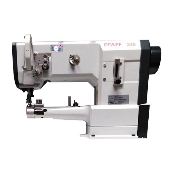
Proper use Proper use The PFAFF 335 is a single needle, free-arm sewing machine with bottom, top and needle feeds for sewing lockstitch seams. Any and all uses of this machine which have not been approved of by the manufacturer are considered to be inappropriate! The manufacturer cannot be... -
Page 10: Specifi Cations
Specifi cations Specifi cations ◆ PFAFF 335 Stitch type: ......................301 ( lockstitch) Model: ..........................B + C Needle system: ......................134 - 35 Needle thickness (Nm) in 1/100 mm: Model B: ........................80 - 100 Model C: ........................110 - 120 Max. -
Page 11: Disposal Of Machine
Disposal of Machine Disposal of Machine ● Proper disposal of the machine is the responsibility of the customer. ● The materials used for the machine are steel, aluminium, brass and various plastic materials. The electrical equipment comprises plastic materials and copper. ●... -
Page 12: Transportation, Packing And Storage
Transportation, packing and storage Transportation, packing and storage Transportation to customer‘s premises The machines are delivered completely packed. Transportation inside the customer‘s premises The manufacturer cannot be made liable for transportation inside the customer‘s premises nor to other operating locations. It must be ensured that the machines are only transported in an upright position. -
Page 13: Explanation Of Symbols
Explanation of symbols Explanation of symbols In this instruction manual, work to be carried out or important information is accentuated by symbols. These symbols have the following meanings: Note, information Cleaning, care Lubrication Maintenance, repairs, adjustment, service work (only to be carried out by technical staff) -
Page 14: Controls
Controls Controls On/off switch ● The power supply to the machine is swit- ched on or off by turning switch 1. The illustrated on/off switch is fi tted to machines with Quick motors. If other motors are used, a different switch may be fi... -
Page 15: Lever For Lifting The Presser Foot
Controls Lever for lifting the presser foot ● The sewing foot can be lifted by raising lever 1. Fig. 7 - 03 Stitch-length adjustment lever / reverse sewing ● Adjust the stitch length by turning the milled nut on lever 1 as required. Reverse sewing ●... -
Page 16: Adjustment Nut For The Top-Feed Stroke
Controls Adjustment nut for the top-feed stroke Switch the machine off! Danger due to unintentional starting of the machine! ● Open cover 1 on the back of the ma- chine, loosen screw 2 and move as re- quired. Fig. 7 - 05 Control panel The description can be found in the separate instruction manual for the motor. -
Page 17: Installation And Commissioning
Installation and commissioning Installation and commissioning The machine must only be mounted and commissioned by qualifi ed personnel! All relevant safety regulations are to be observed! If the machine is delivered without a table, it must be ensured that the frame and the table top which you intend to use can hold the weight of the machine and the motor. -
Page 18: Mounting The Table Top (On Machines With Drive Mj-0-00-215-Ce)
Installation and commissioning Mounting the table top .01.02 (on machines with drive MJ-0-00-215-CE) -
Page 19: Fitting The Upper Belt Guard
Installation and commissioning Fitting the upper belt guard .01.03 If a large balance wheel is used, the corner 1 of the belt guard 3 must be broken out. ● Screw stop piece 2 onto belt guard part 3. ● Screw on belt guard part 3 onto the housing. -
Page 20: Fitting The Reel Stand
Installation and commissioning Fitting the reel stand .01.05 ● Fit the reel stand as shown in Fig. 8 - 07. ● Afterwards insert the stand in the hole in the table top and secure it with nuts pro- vided. Fig. 8 - 05 Connecting the plug-in connections and earth cables Fig. -
Page 21: Commissioning
Installation and commissioning Commissioning ● Check the machine, particularly its electrical wiring and pneumatic tube connections, for any damage. ● Clean the machine thoroughly and oil it (see chapter 10 Care and maintenance). ● Have skilled personnel check if the machine can be operated with the available mains vol- tage. -
Page 22: Setting Up
Setting up Setting up All instructions and regulations in this instruction manual must be observed. Special attention must be given to all safety regulations! All setting-up work must only be done by personnel with the necessary train- ing. For all setting-up work the machine must be isolated from its power supply by turning off the on/off switch or removing the machine plug from the electric power socket! Inserting the needle... -
Page 23: Winding The Bobbin Thread, Adjusting The Thread Tension
Setting up Winding the bobbin thread, adjusting the thread tension Fig. 9 -02 ● Place an empty bobbin 1 onto bobbin shaft 2. ● Thread the bobbin in accordance with Fig. 9-02 and wind it anti-clockwise around bobbin 1 a few times. ●... -
Page 24: Removing / Inserting The Bobbin Case
Setting up Removing / Inserting the bobbin case Switch the machine off! Danger due to unintentional starting of the machine! Removing the bobbin case: ● Lift latch 1 and take out bobbin case 2. Inserting the bobbin case: ● Insert full bobbin case 2 so that you feel it snap in place. -
Page 25: Threading Needle Thread/Adjusting Needle Thread Tension
Setting up Threading needle thread/adjusting needle thread tension Fig. 9 - 05 Switch the machine off! Danger due to unintentional starting of the machine! ● Thread needle thread as shown in Fig. 9-05. ● Be sure to thread the needle from the left. ●... -
Page 26: Care And Maintenance
Care and maintenance Care and maintenance Care and maintenance intervals Cleaning ............daily, in continuous operation several times General oiling ....................twice a week Oil the hook ..............daily, before putting into operation Oil needle-head parts ..................twice a week Lubricate the bevel gears ..................once a yea Lubricate the top-feed drive eccentric .............. -
Page 27: General Oiling
● Tighten screw 1 again. Only use oil with a viscosity of 22.0 mm /s at 40° C and a den- sity of 0.865 g/cm at 15°C! We recommend PFAFF sewing- machine oil, part Fig. 10 - 03a No. 280-1-120 144. -
Page 28: Oiling The Sewing Hook
Only use oil with a viscosity of 22.0 mm /s at 40° C and a den- sity of 0.865 g/cm at 15°C! We recommend PFAFF sewing- machine oil, part No. 280-1-120 144. Fig. 10 - 04 Oiling the needle-head parts... -
Page 29: Lubricating The Bevel Gears
Use both hands to set the sewing head upright! Danger of crushing between the sewing head and the table top! ● Retighten screw 2. We recommend PFAFF sodium grease with a dripping point of approx. 150C, Order No. 280-1-120 243. -
Page 30: Lubricating The Top-Feed Drive Excentric
● Screw cover 1 back on. Only use lithium base grease with a dripping point of 185°C and a worked penetration of 22-25 mm at 25°C. We recommend Pfaff sewingmachine grease Part no. 280-1-120 247 Fig. 10 - 07 Checking/regulating the air pressure ●... -
Page 31: Emptying/Cleaning The Water Bowl Of The Air Fi Lter/Regulator
Care and maintenance Emptying/cleaning the water bowl of the air fi lter/regulator Switch off the machine. Disconnect the air hose at the air fi lter/regulating unit. Emptying the water bowl ● Water bowl 1 empties itself automatically when the air hose is disconnected from the air fi... -
Page 32: Wearing Parts
System 134 - 35 91-100 366-15 91-000 277-25 (2x) 91-001 027-15 (2x) Subclass -940/01 91-173 664-15 91-000 452-15 (2x) Subclass -940/01 91-000 625-15 (2x) 91-000 338-15 (2x) 91-100 024-25 (2x) Subclass -940/01 PFAFF 335-G 91-141 970-91 91-141 971-91 91-174 480-05... - Page 33 Wearing parts 99-137 151-45 91-171 049-05 91-171 042-05 95-774 464-25 91-700 996-15 PFAFF 335-900/52 91-000 094-25 (2x) 91-165 505-05 91-014 046-05 11-108 084-15 (2x) 91-000 452-15 (2x) 91-010 023-05...
- Page 34 PFAFF Industriesysteme und Maschinen AG Hans-Geiger-Str. 12 - IG Nord D-67661 Kaiserslautern Phone: +49 - 6301 3205 - 0 Fax: +49 - 6301 3205 1386 E-mail: info@pfaff-industrial.com Hotlines: Technical service: +49 - 175/2243-101 Application consultance: +49 - 175/2243-102 Spare-parts hotline:...