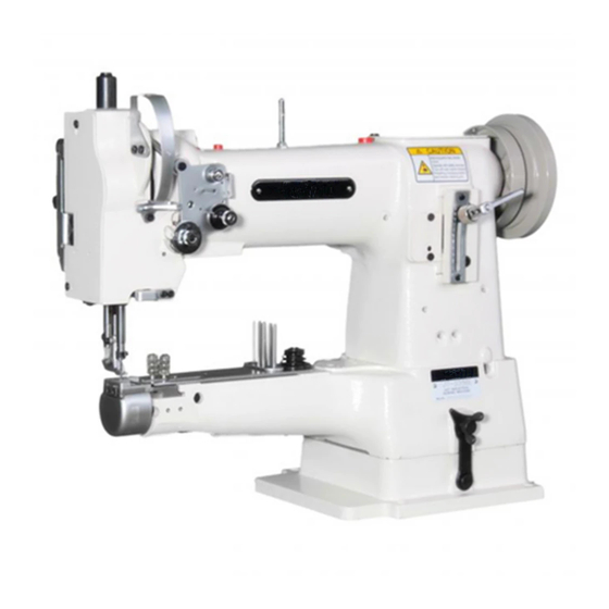
Pfaff 335 Adjustment Manual
Hide thumbs
Also See for 335:
- Instruction manual (62 pages) ,
- Instruction manual (44 pages) ,
- Instruction manual (34 pages)

Related Manuals for Pfaff 335


Summary of Contents for Pfaff 335
- Page 1 Adjustment Manual This Adjustment Manual is valid for machines from the following serial numbers onwards: # 2 734 226 296-12-18 642/002 Justieranleitung engl. 12.06...
- Page 2 The reprinting, copying or translation of PFAFF Service Manuals, whether in whole or in part, is only permitted with our previous authorization and with written reference to the source. PFAFF Industrie Maschinen AG Postfach 3020 D-67653 Kaiserslautern Königstr. 154 D-67655 Kaiserslautern...
-
Page 3: Table Of Contents
Index Contents ..................Page Adjustment ........................... 5 Notes on adjustment ......................5 Tools, gauges and other accessories for adjusting ............... 5 Abbreviations ......................... 5 Explanation of the symbols ....................5 Adjusting the basic machine ....................6 .04.01 Lateral positioning of the feed dog ..................6 .04.02 Lengthwise positioning of the feed dog ................ - Page 4 Index Contents ..................Page Parameter settings (only on machines with Quick-EcoDrive and control unit P40ED)..31 .06.01 Parameter list........................31 Circuit diagrams......................... 32...
-
Page 5: Adjustment
Adjustment Adjustment Please observe all notes from Chapter 1 Safety of the instruction manual! In particular care must be taken to see that all protective devices are refitted properly after adjustment, see Chapter 1.06 Danger warnings of the instruction manual! If not otherwise stated, the machine must be disconnected from the electrical power supply. -
Page 6: Adjusting The Basic Machine
Adjustment Adjusting the basic machine Lateral positioning of the feed dog .04.01 Requirement The clearances from the left and right of the bottom feed dog 1 to the needle plate cutout must be the the same size. Fig. 13 - 01 Move the bottom feed dog 1 (screws 2) in accordance with the requirement. -
Page 7: Lengthwise Positioning Of The Feed Dog
Adjustment Lengthwise positioning of the feed dog .04.02 Requirement With the stitch length set at its longest the clearances behind and in front of the bottom feed dog 4 to the needle plate cutout must be the same. Fig. 13 - 02 Set the longest stitch length. -
Page 8: Height Of The Bottom Feed Dog (Only On Machines With Lifting Phase - P-Version)
Adjustment Height of the bottom feed dog .04.03 (only on machines with lifting phase – P-version) Requirement When the stitch length is set at "0", in its highest position the bottom feed dog 4 should be 0.8 - 1.1 mm above the top edge of the needle plate. Fig. -
Page 9: Centering The Needle In The Needle Hole
Adjustment Centering the needle in the needle hole .04.04 Requirement With the stitch length set at "0" the needle must enter the needle hole exactly in the middle. Fig. 13 - 04 ● Unscrew the vibrating presser foot 1 and the presser foot 2. ●... -
Page 10: Pre-Adjusting The Needle Height
Adjustment Pre-adjusting the needle height .04.05 Requirement With the needle bar at its bdc the distance between the needle bar and the needle plate must be 15 mm. Fig. 13 - 05 Move the needle bar 1 (screw 2) in accordance with the requirement without twisting it. ●... -
Page 11: Driving Motion Of The Top And Bottom Feed Dogs
Adjustment Driving motion of the top and bottom feed dogs .04.06 Requirement With the longest stitch length set and the needle bar at its bdc the top and bottom feed dogs should not move when the reverse feed lever is activated. Fig. -
Page 12: Lifting Motion Of The Bottom Feed Dog (Only On Machines With Lifting Phase - P-Version)
Adjustment Lifting motion of the bottom feed dog .04.07 (only on machines with lifting phase – P-version) Requirement With the needle bar positioned at b.d.c., the bottom feed doc should be in the t.d.c. position. With the maximum stitch length set, when the balance wheel is turned the bottom feed dog should reach the needle plate surface at the same time as the needle point. -
Page 13: Needle Rise, Hook-To-Needle Clearance And Needle Height
Adjustment Needle rise, hook-to-needle clearance and needle height .04.08 Requirement With the stitch length set at "3" (1.8 mm after the bdc of the needle bar) the following must be correct: The hook point must be opposite the middle of the needle and the distance to the needle must be 0.05 - 0.1 mm. -
Page 14: Vibrating Presser Lift
Adjustment Vibrating presser lift .04.09 Requirement With the vibrating presser lift at maximum and the stitch length set at "0", presser foot 1 and vibrating presser foot 2 must lift 7.0 mm from the needle plate when the handwheel is rotated. Fig. -
Page 15: Vibrating Presser Feeding Motion
Adjustment Vibrating presser feeding motion .04.10 Requirement With the presser foot 3 resting on the needle plate the vibrating presser 6 and the needle point must both reach the needle plate at the same time with the vibrating presser stroke at maximum. -
Page 16: Needle Thread Tension Release
Adjustment Needle thread tension release .04.11 Requirement With the presser foot lifted, the two tension disks must be at least 0.5 mm apart. The distance of 0.5 mm is the minimum clearance. The clearance can range up to more than 1 mm with thick threads. 0,5 mm Fig. -
Page 17: Thread Check Spring
Adjustment Thread check spring .04.12 Requirement The movement of the thread check spring must be finished when the needle point enters the material (= approx. 7 mm spring movement). The length of the spring movement can vary a little upwards or downwards due to changes in the sewing parameters. -
Page 18: Bobbin Winder
Adjustment Bobbin winder .04.13 Requirement With the bobbin winder engaged the winder spindle must be driven reliably. With the bob- bin winder disengaged, however, the friction wheel 5 must not touch the drive wheel 1. The bobbin winder must stop automatically when the thread wound on the bobbin has reached a point approx. -
Page 19: Regulating The Pressure On The Presser Foot
Adjustment Regulating the pressure on the presser foot .04.14 Requirement The material must be fed perfectly even at top sewing speed. There must not be any pressure marks on the material. Fig. 13 - 14 Turn screw 1 in accordance with the requirement. ●... -
Page 20: Adjusting The Thread Trimmer -900/52
Adjustment Adjusting the thread trimmer -900/52 Please note that on all machines with thread trimmer -900/52 the stitch length must be limited to 5.5 mm! Preadjusting the control cam .05.01 Requirement With the take-up lever at its bdc, projection 4 on the control cam 2 must be directly un- derneath the cam follower 5. -
Page 21: Tripping Lever Height
Adjustment Tripping lever height .05.02 Requirement With the needle bar at its bdc there must be a distance of 1.0 mm between the tripping lever 3 and the control cam 4. Fig. 13 - 16 ● Bring the needle bar to its bdc by turning the handwheel. ●... -
Page 22: Control Pin
Adjustment Control pin .05.03 Requirement With the needle bar at b.d.c. control pin 5 must drop easily into the track of control cam 7 when engaging solenoid 6 is operated. Fig. 13 - 17 Set the needle bar at b.d.c. ●... -
Page 23: Engaging Solenoid
Adjustment Engaging solenoid .05.04 Requirement With the needle bar at b.d.c. and solenoid core 1 fully operated there must be a clearance of approx. 0.5 mm between locking pawl 7 and fixing collar 6. Fig. 13 - 18 Set the needle bar at b.d.c. ●... -
Page 24: Control Pin Height
Adjustment Control pin height .05.05 Requirement With the thread trimmer in its resting position and locking pawl 4 engaged there must be a clearance of 0.3 mm between the highest point of control cam 5 and control pin 6. Fig. 13 - 19 Set the needle bar at t..d.c. -
Page 25: Front Position Of Thread Catcher
Adjustment Front position of thread catcher .05.06 Requirement With thread catcher 3 at its front position the back edge of the thread catcher cutout must be 1 mm beyond the front edge of bobbin case position stop 6. Fig. 13 - 20 Set the needle bar at b.d.c. -
Page 26: Lateral Position Of Thread Catcher
Adjustment Lateral position of thread catcher .05.07 Requirement With the needle bar at b.d.c. the point of thread catcher 4 must be at the centre of the needle. Fig. 13 - 21 Remove knife 1 (screws 2). ● Set the needle bar at b.d.c. ●... -
Page 27: Control Cam (Final Adjustment)
Adjustment Control cam .05.08 (final adjustment) Requirement When the end of hook gib 2 is 2 mm behind the centre of bobbin-case position finger 3, as viewed in feeding direction, there must be a clearance of approx. 4 mm between catcher point 4 and hook gib 2. -
Page 28: Knife
Adjustment Knife .05.09 Requirement When the back edge of the thread catcher cutout is 1 mm in front of the knife edge, the left knife edge must be flush with the edge of the thread catcher. Fig. 13 - 23 Screw on knife 1 (screws 2) finger-tight. -
Page 29: Needle Thread Tension Release
Adjustment Needle thread tension release .05.10 Requirement When the tip of release lever 5 is at the highest point of release cam 4 the tension discs must be at least 0.5 mm apart. Fig. 13 - 24 Lower the lifting presser onto the needle plate. ●... -
Page 30: Cutting Test
Adjustment Cutting test .05.11 Requirement The knife must stand parallel to the thread catcher and both threads must be reliably cut. Fig. 13 - 25 Set the needle bar at b.d.c. and operate solenoid core 1. ● Turn balance wheel (sewing direction) until thread catcher 2 is in its front position. ●... -
Page 31: Parameter List
Adjustment Parameter settings (only on machines with Quick-EcoDrive and control unit P40ED) ● The selection of the user level and the alteration of parameters is described in the sepa- rate instruction manual for the drive unit. Parameter list .06.01 Speed for start backtack B, C 300 - 2000 Speed for end backtack... -
Page 32: Circuit Diagrams
Circuit diagrams Stromlaufpläne Circuit diagrams Reference list for the Circuit diagrams Control unit Quick P40 ED Control panel BDF S2 Sewing head recognition system (OTE) Sewing lamp (optional) LED stitch counter Sewing motor Main switch Manual backtacking key S1.1 Pedal speed control unit Needle position change key Single stitch key Start inhibitor (E6 stop) -
Page 33: Circuit Diagram
91-191 502-95 Circuit diagram Part 1 Version 07 .07 .06... - Page 34 Circuit diagram 91-191 502-92 Version 07 .07 .06 Part 2...
- Page 35 91-191 502-95 Circuit diagram Part 3 Version 07 .07 .06...
- Page 36 PFAFF Industrie Maschinen AG Postfach 3020 D-67653 Kaiserslautern Königstr. 154 D-67655 Kaiserslautern Telefon: (0631) 200-0 Telefax: (0631) 17202 E-Mail: info@pfaff-industrial.com...