
Related Manuals for IOGear GCS1716


Summary of Contents for IOGear GCS1716
- Page 1 Installation Guide Installation 16-Port USB PS/2 Combo KVM Switch GCS1716 PART NO. M1074...
- Page 2 All information furnished here is for informational purposes only and is subject to change without notice. IOGEAR, Inc. assumes no responsibility for any inaccuracies or errors that may appear in this document.
-
Page 3: Table Of Contents
Table of Contents Firmware Upgrade Utility Package Contents Requirements Limited Warrany Product Overview Federal Communications Commission (FCC) Statement Features Contact Hardware overview Technical Support Hardware Setup Specifications Basic Operation Troubleshooting OSD Operation Appendix Keyboard Port Operation Keybard Emulation... -
Page 4: Package Contents
* Upgraded firmware may have been developed since you last purchased the product. Please visit our website to check and download the latest firmware version. ** Features may have been added to the GCS1716 since this manual was printed. Please visit our website to download the most up-to-date version of the manual. -
Page 5: Requirements
For optimum signal integrity (or to another switch if 10 ft G2L-5203P and to simplify the layout, use the high quality cascading) connection 20 ft G2L-5206P IOGEAR custom cable sets described below. 6 ft G2L-5202U 10 ft G2L-5203U 16 ft G2L-5205U... - Page 6 Operating Systems Supported operating systems are shown in the table, below: Version Windows 2000 or higher, XP, Vista Linux RedHat 7.1 or higher, Fedora Core 2, Fedora Core 3, Fedora Core 4 SuSE 8.2, 9.3, 10 Mandriva (Mandrake)
-
Page 7: Product Overview
1U system rack. The GCS1716 includes one USB port located on the front panel for easy access and sharing of any USB peripherals. Setup is fast and easy; plugging cables into their appropriate ports is all that is needed. The switch supports both USB and PS/2 connections for the console and computers. -
Page 8: Features
Features • A single console controls up to 256 computers • Cascade to 2 levels – connect up to 16 switches • Front panel USB port allows each computer to access USB peripherals* • Dual Interface – supports computers with PS/2 or USB keyboards and mice •... - Page 9 an administrator with a separate profile for each • Auto Scan feature for monitoring user-selected computers • Broadcast mode – operations simultaneously performed on all selected computers • Hot pluggable – add or remove computers without having to power down the switch •...
-
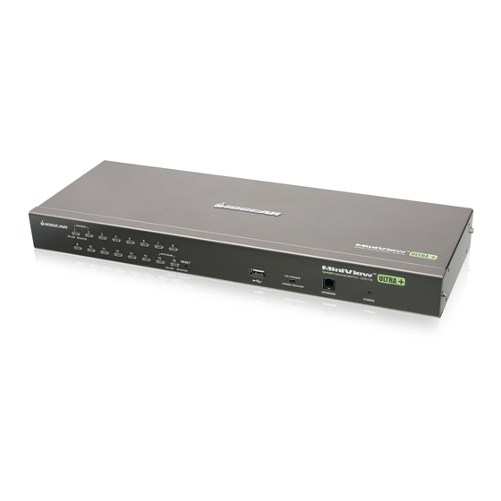
Page 10: Hardware Overview
Hardware Overview Front view... - Page 11 Pressing this button performs a system reset. When the system is reset, the Button GCS1716 beeps, and then the KVM port LEDs flash in succession until the reset is completed. After the reset is complete, you can login again. Note: This button is semi-recessed and must be pushed with a small object, such as the end of a paper clip or a thin ballpoint pen.
- Page 12 Firmware The firmware upgrade cable that transfers the firmware upgrade data from the Upgrade administrator’s computer to the GCS1716, plugs into this RJ-11 connector. Port Power LED Lights green to indicate that the unit is receiving power.
-
Page 13: Back View
Back view CONSOLE PS/2-USB... - Page 14 Do NOT attempt to use ordinary 15-pin VGA connector cables to link these ports to the computers. Grounding The grounding wire used to ground the GCS1716 attaches here. Terminal Cable Tie Slot If you want to use a cable tie to gather the cables together, you can run it through this slot to attach it to the unit.
-
Page 15: Hardware Setup
Keyboard Power On function. Stacking and Rack Mounting The GCS1716 can be stacked on a desktop or rack mounted by a variety of different methods in 1U of rack space. The procedures for each method are described in the following sections. - Page 16 Stacking The GCS1716 can be placed on any level surface that can safely support its weight and the weight of the attached cables. Ensure that the surface is clean and free of materials that can block the exhaust vents or otherwise interfere with the switch normal operation.
- Page 17 Rack Mounting Remove the screws from the left and right sides of the switch (2 screws total) near the front of the switch.
- Page 18 Use the M3 x 8 Phillips hex head screws supplied with the rack mounting kit to screw the rack mounting brackets into the sides near the front of the unit.
- Page 19 Place the KVM switch in the rack. Position it so that the holes in the mounting brackets line up with the holes in the rack. Secure the mounting brackets to the front of the rack.
- Page 20 Grounding To prevent damaging your equipment, it is important that all devices are properly grounded. Use the included grounding wire to ground the KVM switch by connecting one end of the wire to the grounding terminal, and the other end of the wire to a suitable grounded object. CONSOLE PS/2-USB...
- Page 21 Single Level Installation In a single level installation, only one switch is utilized. To set up, do the following: Make sure that that switch is grounded and power has been turned off to all the computers you will be connecting. Using the console cable provided, connect a keyboard, mouse, and monitor to the console port.
- Page 22 Using a KVM cable connect it an available KVM port on the GCS1716. Make sure to connect the keyboard, video and mouse ports to the computer you are installing. Refer to the KVM Cable Installation Diagrams on the following page.
- Page 23 Note: The cascading feature will only be available on products that will ship after January 2009. If you purchased a GCS1716 prior to January 2009, you can add the cascading feature by simply upgrading the Firmware. Visit www.iogear.com/support for the latest updates.
- Page 24 Using a cascading cable, connect the available CPU port on the upper level GCS1716, to the console port on the lower level GCS1716. Refer to the diagram on page 27. Repeat the above step #3 for any additional switches you wish to add by connecting the second unit to another available CPU port on the first GCS1716.
- Page 25 Console Cable Installation Diagram CONSOLE PS/2-USB PS/2...
- Page 26 KVM Cable Installation Diagrams USB KVM Cable Connection PS/2 KVM Cable Connection...
- Page 27 Cascading Installation Diagram CONSOLE PS/2-USB CONSOLE PS/2-USB...
-
Page 28: Basic Operation
Basic Operation Hot Plugging The GCS1716 supports hot plugging – components can be removed and added back into the installation by unplugging their cables from the ports without the need to shut the unit down. However, in order for hot plugging to work properly, the procedures described below must be followed:... - Page 29 Mouse Reset by simultaneously pressing the 1 and 2 front panel port LEDs. Port Selection The GCS1716 provides three port selection methods to access the computers on the installation: 1) Manual, 2) An On-Screen Display (OSD) menu system, and...
- Page 30 Use the front panel push button switches to manually switch to a port. Powering Off and Restarting If it becomes necessary to power off a GCS1716, do the following before restarting it: Unplug the unit from its power source. Shut down all the computers that are attached to it.
- Page 31 The front panel USB port is available to connect a USB peripheral device such as a flash drive, CD-ROM drive, printer, etc. Any computer connected to the GCS1716 can access the USB peripheral on a one at-a-time basis. The peripheral device is available to computers connected to the GCS1716 on the same level only, and is not available to computers connected to cascading switches.
-
Page 32: Osd Operation
You can display the OSD on the console monitor while also viewing the display of any port on the GCS1716 by pressing the [Scroll Lock] key twice. Note: You can optionally change the OSD hotkey to the Ctrl key, in which case you would press [Ctrl]... - Page 33 OSD Main Screen When you invoke the OSD, a screen similar to the one below appears: Notes: The diagram depicts the administrator’s main screen. The user main screen does not show the F4 and F6 functions, since these are reserved for the administrator and can’t be accessed by users. The OSD always starts in list view, with the highlight bar at the same position it was in the last time it was closed.
- Page 34 OSD Main Screen Headings This column lists the port ID numbers for all the KVM ports on the installation. The simplest method to access a particular computer is move the highlight bar to it then press Enter. If a port is selected for quick view scanning an arrowhead shows in this column. INSERT A SUN The computers that are powered on and are online will a sun symbol in this SYMBOL...
- Page 35 OSD Navigation • To dismiss the menu, and deactivate OSD, click the X in the upper right corner of the OSD window; or press [Esc]. To log out, click F8 at the top of the main screen, or press [F8]. •...
- Page 36 OSD Functions OSD functions are used to configure and control the OSD. For example, you can rapidly switch to any port, scan selected ports, limit the list you wish to view, designate a port as a quick view port, create or edit a port name, or make OSD setting adjustments.
- Page 37 F2: LIST This function lets you broaden or narrow the scope of which ports the OSD displays on the main screen. The submenu choices and their meanings are given in the table below. Choice Meaning Lists all of the ports on the installation that have been set accessible by the administrator for the current logged in user.
- Page 38 F3: SET This function allows the administrator and each user to set up his own working environment. A separate profile for each is stored by the OSD and is activated according to the username that was provided during login. To change a setting: Double-click it, or move the highlight bar to it, then press [Enter].
- Page 39 PORT ID DISPLAY Determines how long a port ID displays on the monitor after a port change has taken place. The DURATION choices are: 3 Seconds (default) and Always Off. PORT ID DISPLAY Selects how the port ID is displayed: the port number plus the port name (PORT NUMBER + MODE PORT NAME) (default);...
- Page 40 SCREEN If there is no input from the console for the amount of time set with this function, the BLANKER screen is blanked. Key in a value from 1–30 minutes, then press [Enter]. The default setting of 0 disables this function. HOTKEY Enables / disables the hotkey command function in case a conflict with programs COMMAND...
- Page 41 Setting Function SET USER This function is used to set usernames and passwords for the administrator and users: LOGIN Usernames and passwords for one administrator and four users can be set. After you select the administrator field or one of the user fields, a screen that allows you to key in the username and password appears.
- Page 42 SET ACCES- This function allows the administrator to define user access to the computers on the SIBLE PORTS installation on a port-by-port basis. For each user, select the target port; then press the [Spacebar] to cycle through the choices: F (full access), V (view only), or blank. Repeat until all access rights have been set then press [Enter].
- Page 43 EDIT PORT To help remember which computer is attached to a particular port, every port can be given NAMES a name. This function allows the administrator to create, modify, or delete port names. To edit a port name: Click the port, or use the navigation keys to move the highlight bar to it then press [Enter].
- Page 44 CLEAR THE This function clears the port name list. NAME LIST ACTIVATE Choices are Y (on), or N (off). When activated, the beeper sounds whenever 1) a port is BEEPER changed, 2) when activating the Auto Scan function or 3 an invalid entry is made on an OSD menu.
- Page 45 This function allows the administrator to define the operating system for the computer con- nected to each KVM port. The default is WIN (PC compatible). To set the port operating system From the list, select the port for which you wish to set the computer’s operating system Set the operating system by pressing [Spacebar] to cycle through WIN, MAC, SUN, or other Press [Esc] to exit.
- Page 46 FIRMWARE In order to upgrade the GCS1716 firmware, you must first enable Firmware Upgrade mode UPGRADE with this setting. When you bring up this menu, the current firmware version levels are displayed. Select Y to enable Firmware Upgrade mode or N to leave the menu as is.
- Page 47 F5: SKP Clicking the F5 field or pressing [F5] invokes Skip (SKP) mode. This function enables you to easily skip backward or forward – switching the console focus from the currently active computer port to the previous or next available one. •...
- Page 48 F6: BRC F6 is an administrator only function. Clicking the F6 field, or pressing [F6], invokes Broadcast (BRC) mode. In that mode, commands sent from the console are broadcast to all available computers on the installation. This function is particularly useful for operations that need to be performed on multiple computers, such as performing a system wide shutdown, installing or upgrading software, etc.
- Page 49 F7: SCAN Clicking the F7 field or pressing [F7] invokes Auto Scan mode. This function allows you to automatically switch among the available computers at regular intervals so that you can monitor their activity without having to take the trouble of switching yourself. •...
- Page 50 F8: LOUT Clicking the F8 field, or pressing [F8] logs you out of OSD control of the computers and blanks the console screen. This is different from simply pressing [Esc] when you are at the main screen to deactivate the OSD. With this function you must log in all over again to regain access to the OSD, whereas with [Esc], all you have to do to reenter the OSD is tap the OSD hotkey.
-
Page 51: Keyboard Port Operation
Keyboard Port Operation Hotkey Port Control Hotkey port control allows you to provide KVM focus to a particular computer directly from the keyboard. The GCS1716 provides the following hotkey port control features: • Selecting the Active Port • Auto Scan Mode Switching •... - Page 52 Invoke Hotkey Mode All hotkey operations begin by invoking Hotkey mode. There are two possible keystroke sequences used to invoke Hotkey mode, though only one can be operational at any given time. Note: Make sure that the Hotkey Command Mode function is enabled and that you key in the appropriate Hotkey.
- Page 53 When Hotkey mode is active: • A command line appears on the monitor screen. The command line prompt is the word Hotkey: in white text on a blue background, and displays the subsequent hotkey information that you key in. • Ordinary keyboard and mouse functions are suspended –...
- Page 54 Press [Enter]. After you press [Enter], the KVM focus switches to the designated computer and you automatically exit hotkey mode. Note: In hotkey mode, KVM focus will not switch to a port if an invalid switch or port number is entered. The hotkey command line will continue to display on the screen until you enter a valid switch and port number combination, or exit hotkey mode.
- Page 55 • When in Auto Scan mode, you can pause the scanning in order to keep the focus on a particular computer either by pressing P or with a left click of the mouse. During the time that auto-scanning is paused, the command line displays: Auto Scan: Paused. Pausing when you want to keep the focus on a particular computer is more convenient than exiting Auto Scan mode because when you resume scanning, you start from where you left off.
- Page 56 Skip Mode This feature allows you to switch between computers in order to monitor them manually. You can dwell on a particular port for as long as you like – as opposed to auto-scanning, which automatically switches after a fixed interval. To invoke Skip mode, key in the following hotkey combination: Invoke hotkey mode with the [Num Lock] + [-] or [Ctrl] + [F12] combination.
- Page 57 • Once you are in Skip mode, you can keep on skipping by pressing the arrow keys. You don’t have to use the [Num Lock] + [-] combination again. • When in Skip mode, ordinary keyboard and mouse functions are suspended – only Skip mode compliant keystrokes can be input.
- Page 58 Hotkey Beeper Control The beeper (see Activate Beeper) can be hotkey toggled on and off. To toggle the beeper, key in the following hotkey combination: Invoke hotkey mode with the [Num Lock] + [-] or [Ctrl] + [F12] combination. Press [B]. After you press [B], the beeper toggles on or off.
- Page 59 OSD Hotkey Control The OSD Hotkey (see OSD Hotkey) can be toggled between [Scroll Lock], [Scroll Lock] and [Ctrl], [Ctrl]. To toggle the OSD Hotkey, key in the following hotkey combination: Invoke hotkey mode with the [Num Lock] + [-] or [Ctrl] + [F12] combination. Press [T].
- Page 60 After pressing a function key you automatically exit Hotkey mode. Restore Default Values This administrator only hotkey restores the GCS1716 default values. See Restore Default Values, page 83. To restore the default values, key in the following hotkey combination: Invoke hotkey mode with the [Num Lock] + [-] or [Ctrl] + [F12] combination.
- Page 61 Hotkey Summary Table [Num Lock] + [-] [A] [Enter] Invokes Auto Scan mode. When Auto Scan mode is in effect, [P] or left-click pauses [Ctrl] + [F12] [Q] [Enter] auto-scanning. When auto-scanning is paused, pressing any key or another left-click resumes auto scanning. Toggles the beeper on or off.
- Page 62 [Num Lock] + [-] [R] [Enter] This administrator only hotkey restores the switch’s default values. See Restore Default Values. [Ctrl] + [F12] [SN][PN] [Enter] Switches access to the computer that corresponds to that port ID. Toggles the OSD Hotkey between [Ctrl] [Ctrl] and [Scroll Lock] [Scroll Lock].
-
Page 63: Keybard Emulation
Keyboard Emulation Mac Keyboard The PC compatible (101/104 key) keyboard can emulate the functions of the Mac keyboard. The emulation mappings are listed in the table below. PC Keyboard Mac Keyboard [Shift] Shift [Ctrl] Ctrl Insert flying window logo Insert Apple menu icon [Ctrl] [1] Insert Apple speaker [Ctrl] [2]... - Page 64 [Ctrl] [4] Insert Apple pyramid [Alt] [Print Screen] [Scroll Lock] Insert left mouse click function icon [Enter] Return [Backspace] Delete [Insert] Help [Ctrl] flying window Note: When using key combinations, press and release the first key (Ctrl), then press and release the activation key.
- Page 65 Sun Keyboard The PC compatible (101/104 key) keyboard can emulate the functions of the Sun keyboard when the control key [Ctrl] is used in conjunction with other keys. The corresponding functions are shown in the table below. PC Keyboard Sun Keyboard [Ctrl] [T] Stop [Ctrl] [F2]...
- Page 66 [Ctrl] [F10] [Ctrl] [1] [Ctrl] [2] [Ctrl] [3] [Ctrl] [4] [Ctrl] [H] Help Compose Note: When using key combinations press and release the first key (Ctrl), then press and release the activation key.
-
Page 67: Firmware Upgrade Utility
The purpose of the Windows-based Firmware Upgrade Utility is to provide an automated process for upgrading all GCS1716 switches in an installation. The program comes as part of a Firmware Upgrade Package that is specific for each device. As new firmware versions become available, they will be posted on our website. Check the website regularly to find the latest information and packages. - Page 68 Use the Firmware Upgrade Cable provided with this unit to connect a COM port on your computer to the Firmware Upgrade Port of your switch. Note: Shut down all of the computers on your KVM installation From your KVM switch console, login to the OSD as the administrator and select the F4 ADM function.
- Page 69 Starting the Upgrade To upgrade the firmware: Run the downloaded firmware upgrade package file either by double clicking the file icon or by opening a command line and entering the full path to it. The Firmware Upgrade Utility welcome screen appears: Note: The screens shown in this section are for reference only.
- Page 70 Read and Agree to the License Agreement (enable the I Agree radio button). Click Next to continue. The Firmware Upgrade Utility main screen appears. The devices capable of being upgraded are listed in the Device List panel.
- Page 71 Click Next to perform the upgrade. If you enabled Check Firmware Version, the Utility compares the device's firmware level with that of the upgrade files. If it finds that the device's version is higher than the upgrade version, it brings up a dialog box informing you of the situation and gives you the option to continue or cancel.
- Page 72 Upgrade Succeeded After the upgrade is complete, a screen appears to inform you that the procedure was successful. Click Finish to close the Firmware Upgrade Utility.
- Page 73 Upgrade Failed If the Upgrade Succeeded screen doesn't appear, it means that the upgrade failed to complete successfully. See the next section, Firmware Upgrade Recovery, for how to proceed. Firmware Upgrade Recovery There are three conditions that call for firmware upgrade recovery: •...
-
Page 74: Limited Warrany
For further inquiries please contact IOGEAR. -
Page 75: Federal Communications Commission
Federal Communications Commission (FCC) Statement This device complies with part 15 of the FCC Rules. Operation is subject to the following two conditions: (1) this device may not cause harmful interference, and (2) this device must accept any interference received, including interference that may cause undesired operation. This device is authorized under 47 CFR 15.519 (the FCC Rules and Regulations). -
Page 76: Contact
Contact IOGEAR 23 Hubble Irvine, CA 92618 P 949.453.8782 F 949.453.8785 Visit us at: www.iogear.com... -
Page 77: Technical Support
To help IOGEAR® customers obtain the highest level of performance from their Wireless USB devices, the IOGEAR® Service Support team is available to answer your technical questions. Do not hesitate to call if you are having trouble getting your device to work correctly. IOGEAR® Service Support can be reached by phone from 24 hours a day, 7 days a week or through the following address during normal business hours. - Page 78 You may also reach us online at www.iogear.com/support 24 hours a day. Please be ready to give a brief description of the problem, and what you were doing when the problem occurred, before calling Service Support. The Service Support representative will be able to serve you much quicker if you are prepared to answer the seven questions listed below.
-
Page 79: Specifications
Specifications Function GCS1716 Computer Direct Connections 256 (via cascading) Port Selection OSD, Hotkeys, Push Buttons switching Connectors Console Port 1 x SPHD-18 KVM Port 16 x SPHD-15 FW Upgrade 1 x RJ-11 USB Port 1 x USB Type A Power 1 x DC Jack LED’s... - Page 80 Emulation Keyboard/Mouse PS/2, USB Video 2048 x 1536; DDC2B Scan Interval (OSD select) User specified: 1-255 sec. Power Consumption DC 5.3 V / 6.6W Environment Operating Temp. 0-50o C Storage Temp. -20-60o C Humidity 0-80% RH, Non-condensing Physical Properties Housing Metal Weight 6.28 lbs (2.85 kg)
- Page 81 Restoring Factory Default Settings You can restore the factory default settings (listed on the next page) for the GCS1716. With this procedure, the administrator and all user accounts are removed from the system. All port names and setting are also removed.
- Page 82 Unplug the power adapter again. Remove the jumper cap from pins 1-2 of the J17 jumper. Replace the cover on the KVM switch. Plug in the GCS1716 power adapter. You should now use the default username and password to log in to the GCS1716...
- Page 83 OSD Factory Default Settings The factory default settings are as follows: Setting Default OSD Hotkey [Scroll Lock] [Scroll Lock] Port ID Display Position Upper Left Corner Port ID Display Duration 3 Seconds Port ID Display Mode Port Number plus Port Name Scan Duration 5 Seconds Scan-Skip Mode...
- Page 84 About SPHD Connectors This product uses SPHD connectors for its KVM and/or Console ports. We have specifically modified the shape of these connectors so that only KVM cables that we have designed to work with this product can be connected.
-
Page 85: Troubleshooting
Troubleshooting Operation problems can be due to a variety of causes. The first step in solving them is to make sure that all cables are securely attached and seated completely in their sockets. In addition, updating the product’s firmware may solve problems that have been discovered and resolved since the prior version was released. -
Page 86: Appendix
Appendix FCC Information This is an FCC Class A product. In a domestic environment this product may cause radio interference in which case the user may be required to take adequate measures. This equipment has been tested and found to comply with the limits for a Class A digital device, pursuant to Part 15 of the FCC Rules. - Page 87 Safety Instructions General • Read all of these instructions. Save them for future reference. • Follow all warnings and instructions marked on the device. • Do not place the device on any unstable surface (cart, stand, table, etc.). If the device falls, serious damage will result.
- Page 88 • The device is designed for IT power distribution systems with 230V phase-to-phase voltage. • To prevent damage to your installation it is important that all devices are properly grounded. • The device is equipped with a 3-wire grounding type plug. This is a safety feature. If you are unable to insert the plug into the outlet, contact your electrician to replace your obsolete outlet.
- Page 89 • The device has been exposed to rain or water. • The device has been dropped, or the cabinet has been damaged. • The device exhibits a distinct change in performance, indicating a need for service. • The device does not operate normally when the operating instructions are followed. •...
- Page 90 • Ensure that proper airflow is provided to devices in the rack. • Ensure that the operating ambient temperature of the rack environment does not exceed the maximum ambient temperature specified for the equipment by the manufacturer. • Do not step on or stand on any device when servicing other devices in a rack.
- Page 92 About Us About Us IOGEAR offers connectivity solutions that are innovative, fun, and stylish, helping people enjoy daily life using our high technology products. GREEN IOGEAR is an environmentally conscious company that emphasizes the importance of conserving natural resources. The use of our technology solutions helps reduce electronic waste.