
Related Manuals for Clarke Woodworker CBS1-5


Summary of Contents for Clarke Woodworker CBS1-5
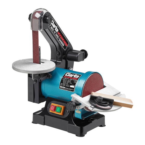
- Page 1 BELT/DISC SANDER MODEL NO: CBS1-5 PART NO: 6500403 OPERATION & MAINTENANCE INSTRUCTIONS GC0414...
-
Page 2: General Safety Rules
INTRODUCTION Thank you for purchasing this CLARKE Belt and Disc Sander, which is designed for hobby, DIY and light workshop use for sanding wood and wood products. Before attempting to use this product, please read this manual thoroughly and follow the instructions carefully. In doing so you will ensure the safety of yourself and that of others around you, and you can look forward to your purchase giving you long and satisfactory service. -
Page 3: Care Of Power Tools
5. KEEP other persons away. Do not let persons, especially children, not involved in the work, touch the tool or extension cable and keep them away from the work area. 6. NEVER operate a machine when under the influence of alcohol, drugs or medication. -
Page 4: Dust Extraction
12. If the machine should be used outdoors, use only extension cables intended for outdoor use and marked accordingly. 13. Avoid accidental starting by making sure the power switch is off before plugging in the power cable. ADDITIONAL PRECAUTIONS FOR BELT & DISC SANDERS 1. -
Page 5: Electrical Connections
ELECTRICAL CONNECTIONS WARNING: READ THESE ELECTRICAL SAFETY INSTRUCTIONS THOROUGHLY BEFORE CONNECTING THE PRODUCT TO THE MAINS SUPPLY. Before switching the product on, make sure that the voltage of your electricity supply is the same as that indicated on the rating plate. This product is designed to operate on 230VAC 50Hz. -
Page 6: Product Overview
PRODUCT OVERVIEW NO DESCRIPTION NO DESCRIPTION Disc Sanding Table Vertical Table Locking Levers Belt Sanding Table Flat Washers (for use with E & F) C Mitre Gauge Rubber Feet Disc Cover/Dust Extract Point Allen Keys Disc Sanding Table Locking Levers WARNING: THE USE OF ANY ACCESSORY/ATTACHMENT OTHER THAN THOSE RECOMMENDED IN THIS INSTRUCTION MANUAL MAY PRESENT A RISK OF PERSONAL INJURY. -
Page 7: Belt Table
ASSEMBLY BELT TABLE 1. Gently ease the table into place with the belt support entering the slot in the table. 2. Screw the Table Locking Lever into place, ensuring a flat washer is used on the levers’ threads. DISC TABLE 1. -
Page 8: Adjustments Before Use
3. Secure with four screws (arrowed). FEET The four feet may be very gently eased into the holes at the base of the machine. Alternatively, the machine may be mounted on a workbench or a wooden base, using the four holes in the base as mounting holes. In order to maintain complete stability when in use, the wooden base should be secured to a workbench using ‘G’... -
Page 9: Disc Table Adjustment
4. Place an engineers square on the table so that it butts up against the belt, then unlock the adjuster by unscrewing the locknut at B. 5. Screw the adjuster A, clockwise or anticlockwise whilst bearing down on the table at a point adjacent to screw A, until the square indicates that the table is at right angles. -
Page 10: Operation
OPERATION IMPORTANT: Ensure that ALL components are secure, ALL correct adjustments have been carried out, and ALL safety precautions have been observed BEFORE plugging the machine into the mains supply, and switching ON. 1. Attach a vacuum cleaner or other dust extraction device to the relevant extraction port (depending upon the medium to be used) and switch it ON. -
Page 11: Changing The Sanding Belt
CHANGING THE SANDING BELT 1. Remove the belt table completely by unscrewing and removing the table locking lever. 2. Remove the two side cover securing screws (A), followed by the upper roller pivot screw (B), then pull off the side cover. 3. -
Page 12: Parts Diagram
PARTS DIAGRAM When requesting spare parts, please quote the reference HT-CBS1-5 followed by the id number listed. Parts & Service: 020 8988 7400 / E-mail: Parts@clarkeinternational.com or Service@clarkeinternational.com... -
Page 13: Parts List
PARTS LIST DESCRIPTION DESCRIPTION DESCRIPTION Knob 31 Screw 61 Pointer Cover 32 Elastic Washer 62 Sliding Bar Label 33 Washer 63 Table Warning Label 34 Wheel 64 Pin Belt 35 Insert 65 Screw Circlip 36 Bolt 66 Spring Bearing 37 Screw 67 Lever Driven Wheel 38 Table... -
Page 14: Replacement Discs And Belts
REPLACEMENT DISCS AND BELTS Sanding Discs 60 grit (pack of 5). Part No: 6502345 Sanding Discs 80 grit (pack of 5). Part No: 6502350 Sanding Discs 120 grit (pack of 5). Part No: 6502355 Sanding Belts 60 grit (pack of 5). Part No: 6502330 Sanding Belts 80 grit (pack of 5). -
Page 15: Declaration Of Conformity
DECLARATION OF CONFORMITY Parts & Service: 020 8988 7400 / E-mail: Parts@clarkeinternational.com or Service@clarkeinternational.com...