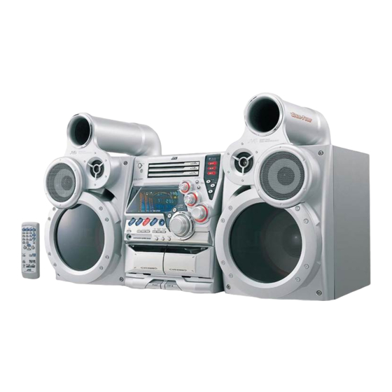
JVC MX-GT90 Service Manual
Compact component system
Hide thumbs
Also See for MX-GT90:
- Instructions manual (34 pages) ,
- Service manual (48 pages) ,
- Instructions manual (34 pages)
Table of Contents
Advertisement
Quick Links
SERVICE MANUAL
COMPACT COMPONENT SYSTEM
SP-MXGT90
(No MIC jack and MIC LEVEL volume for UY ver.)
Contents
Safety precautions
Important for laser products
Preventing static electricity
Disassembly method
Adjustment method
MX-GT90
STANDBY/ON
STANDBY
CD-R / RW PLAYBACK
MX-GT90
CA-MXGT90
1-2
Flow of functional operation
1-3
1-4
Maintenance of laser pickup
1-5
Replacement of laser pickup
1-25
Description of major ICs
COPYRIGHT
2001 VICTOR COMPANY OF JAPAN, LTD.
US
UW
UY
PLAY & EXCHANGE
SP-MXGT90
until TOC read
MX-GT90
Area Suffix
Singapore
Brazil,Mexico,Peru
Argentina
1-29
1-30
1-30
1-31~50
No.20996
Jun. 2001
Advertisement
Table of Contents

Related Manuals for JVC MX-GT90


Summary of Contents for JVC MX-GT90
- Page 1 MX-GT90 SERVICE MANUAL COMPACT COMPONENT SYSTEM MX-GT90 Area Suffix Singapore Brazil,Mexico,Peru Argentina STANDBY/ON STANDBY PLAY & EXCHANGE CD-R / RW PLAYBACK MX-GT90 SP-MXGT90 SP-MXGT90 CA-MXGT90 (No MIC jack and MIC LEVEL volume for UY ver.) Contents Safety precautions Flow of functional operation...
- Page 2 MX-GT90 1. This design of this product contains special hardware and many circuits and components specially for safety purposes. For continued protection, no changes should be made to the original design unless authorized in writing by the manufacturer. Replacement parts must be identical to those used in the original circuits. Services should be performed by qualified personnel only.
-
Page 3: Important For Laser Products
MX-GT90 Important for laser products 5.CAUTION : If safety switches malfunction, the laser is able 1.CLASS 1 LASER PRODUCT to function. 2.DANGER : Invisible laser radiation when open and inter 6.CAUTION : Use of controls, adjustments or performance of lock failed or defeated. Avoid direct exposure to beam. -
Page 4: Preventing Static Electricity
MX-GT90 Preventing static electricity 1. Grounding to prevent damage by static electricity Electrostatic discharge (ESD), which occurs when static electricity stored in the body, fabric, etc. is discharged, can destroy the laser diode in the traverse unit (optical pickup). Take care to prevent this when performing repairs. -
Page 5: Disassembly Method
MX-GT90 Disassembly method Metal cover <Main body> Removing the metal cover (See Fig.1 to 3) Remove the six screws A on the back of the body. Remove the two screws B on both sides of the body. Remove the metal cover from the body by lifting the rear part of the cover. - Page 6 MX-GT90 Removing the CD changer mechanism assembly (See Fig.4 to 6) Front panel assembly Prior to performing the following procedure, remove the metal cover. Disconnect the card wire from connector CN561 on the main board. Remove the two screws C on the upper side of the...
- Page 7 MX-GT90 Main board Amplifier board Tie band Removing the front panel assembly CN870 CN703 (See Fig.6 to 10) CN871 CN705 Prior to performing the following procedure, remove CN315 the metal cover and CD changer mechanism assembly. Disconnect the card wires from connector CN870, CN871 and CN315 on the main board respectively.
- Page 8 MX-GT90 Removing the tuner board Plastic rivet Tuner board (See Fig.11 and 12) Prior to performing the following procedure, remove Rear panel the metal cover and the CD changer mechanism assembly. Disconnect the card wire from connector CN1 on the tuner board on the right side of the body.
- Page 9 MX-GT90 Main board Removing the main board Front panel assembly CN870 (See Fig.16 and 17) CN871 CN315 Prior to performing the following procedure, remove the metal cover, the CD changer mechanism Amplifier board assembly, the rear panel and the tuner board.
- Page 10 MX-GT90 Voltage selector board Tie band Removing the voltage selector board (See Fig. 19) Prior to performing the following procedure, remove the metal cover, the CD changer mechanism assembly and the rear panel. Disconnect the wires from connector CN218, CN219...
- Page 11 MX-GT90 Removing power transformer Transformer board CN220 Voltage selector Tie band assembly (See Fig.22 and 23) board CN219 Prior to performing the following procedure, remove the metal cover, the CD changer mechanism assembly and the rear panel. Disconnect the wires from connector CN218 and...
-
Page 12: Front Panel Assembly
MX-GT90 <Front panel assembly> Head amplifier & Mechanism control board CN306 Prior to performing the following procedure, remove the metal cover, the CD changer mechanism assembly and the front panel assembly. Removing cassette mechanism assembly (See Fig.25) Disconnect the card wire from connector CN306 on the head amplifier &... - Page 13 MX-GT90 Preset / tuning switch board Removing the preset / tuning switch board (See Fig.30 and 31) Prior to performing the following procedure, remove the display system control board. Pull out the preset knob on the front panel. Remove the five screws R attaching the preset / tuning switch board.
- Page 14 MX-GT90 Removing the CD Servo control board (See Fig.1) 1.Remove the metal cover. 2.Remove the CD changer mechanism assembly. 3.From bottom side the CD changer mechanism assembly, remove the four screws A retaining the CD servo control CN854 board. 4.Absorb the four soldered positions "a" of the right and left motors with a soldering absorber.
- Page 15 MX-GT90 Stopper Check whether the lifter unit stopper has been caught into the hole at the section "e" of CD tray assembly as shown in Fig.5. Make sure that the driver unit elevator is positioned as shown in Fig.6 from to the second or fifth hole on the left side face of the CD changer mechanism assembly.
- Page 16 MX-GT90 Cams R1, R2 assembly Removing the CD loading mechanism assembly(See Fig.10) While turning the cams R1 and R2 assembly in the arrow direction "h" ,align the shaft "i" of the CD loading mechanism assembly to the position shown in Fig.10.
-
Page 17: See Fig
MX-GT90 Removing the try select switch board Chassis assembly (See Fig.14) Remove the two screws G retaining the tray select switch board. Tray select switch board Disconnect the tray select switch board from connector CN804 on the CD servo control board. - Page 18 MX-GT90 Removing the actuator motor and belt Gear bracket (See Fig.18~21) Remove the two screws I retaining the gear bracket (See Fig.18). While pressing the pawl "t" fixing the gear bracket in the arrow direction, remove the gear bracket Pulley gear (See Fig.18).
- Page 19 MX-GT90 Slit washer Removing the cams R1/R2 assembly and cam gear q(See Fig.22) Cam R2 Slit washer Remove the slit washer fixing the cams R1 and R2 assembly. Cam gear q By removing the two pawls "w" fixing the cam R1, separate R2 from R1.
-
Page 20: Cassette Mechanism Section
MX-GT90 < Cassette mechanism section > Cassette mechanism Removing the playback,recording and eraser heads (See Fig.1~3) 1. While shifting the trigger arms seen on the right side of the head mount in the arrow direction,turn Flywheel R the flywheel R in counterclockwise direction until the head mount has gone out with a click (See Fig. - Page 21 MX-GT90 Removing the head amp. and mechanism control board (See Fig. 4) 1.Remove the cassette mechanism assembly. Head amplifier & 2.After turning over the cassette mechanism mechanism control board assembly,remove the five screws "A" retaining the head amplifier & mechanism control board.
- Page 22 MX-GT90 Removing the capstan motor (See Fig. 8) Capstan motor From the joint bracket, remove the two screws "C" retaining the capstan motor. Joint bracket Removing the flywheel (See Fig. 9,10) 1.Remove the head amp. and mechanism control P.C.Board. 2.Remove the capstan motor assembly.
- Page 23 MX-GT90 Speaker section Removing the front panel (See Fig.1 and 2) Remove the four screws A attaching the front panel on the front of the body. Pull out the front panel toward the front and Front panel disconnect the wire from the two speaker terminals of the speaker (tweeter) on the back of the front panel.
- Page 24 MX-GT90 Removing the speaker (squawker) (See Fig.5) Speaker (squawker) Prior to performing the following procedures, remove the front panel. Remove the four screws E attaching the speaker (squawker) on the front of the body. Disconnect the wire from the two speaker terminals of the speaker (squawker).
-
Page 25: Adjustment Method
MX-GT90 Adjustment method Measurement instruments required for adjustment Radio input signal 1. Low frequency oscillator, AM modulation frequency : 400Hz This oscillator should have a capacity to output 0dBs Modulation factor : 30% to 600ohm at an oscillation frequency of 50Hz-20kHz. - Page 26 MX-GT90 Arrangement of adjusting positions Cassette mechanism section (Mechanism A section) Cassette mechanism section (Back side) Head azimuth Head azimuth adjusting screw adjusting screw (Reverse side) (Forward side) Head azimuth Head azimuth Playback, recording and eraser adjusting screw adjusting screw...
- Page 27 MX-GT90 Tape recorder section Adjusting Items Measurement Standard Measurement method positions conditions values Confirmation Adjust the head Test tape Maximum 1.Playback the test tape TMT7036(10kHz). of head angle azimuth screw :TMT7036(10kHz) output 2.With the playback mechanism or recording & only when the...
- Page 28 MX-GT90 Electrical performance Adjusting Items Measurement Standard Measurement method positions conditions values Adjustment of AC-225 *Mode : Forward or 1.With the recording and playback mechanism, recording bias :4.20 A reverse mode load the test tapes(AC-225 to TYP ),and set the...
-
Page 29: Flow Of Functional Operation Until Toc Read
MX-GT90 Flow of functional operation until TOC read Check Point Slider turns REST Play Key Power ON Confirm that the voltage at the pin5 SW ON. of CN801 is "H"\"L"\"H". Automatic tuning of TE offset Check that the voltage at the... -
Page 30: Replacement Of Laser Pickup
MX-GT90 Replacement of laser pickup Maintenance of laser pickup (1) Cleaning the pick up lens Before you replace the pick up, please try to Turn off the power switch and, disconnect the clean the lens with a alcohol soaked cotton power cord from the ac outlet. -
Page 31: Description Of Major Ics
MX-GT90 Description of major ICs AN7345(IC302) : PB/REC amp. 1. Block diagram OUT1 CTL1 RIN1 RNF1 ROUT1 REPPLE Source CTRL CTRL EQ2 CTL2 OUT2 RIN2 RNF2 ROUT2 2. Pin Function Symbol Function Symbol Function Power supply Playback amplifier input Ripple filter... - Page 32 MX-GT90 BA15218F-XE (IC652) / BA15218N (IC481,501,502,526,571) : Dual op. amp. 1. Pin layout OUT1 1 8 Vcc -IN1 2 7 OUT2 +IN1 3 6 -IN2 VEE 4 5 +IN2 2. Block diagram OTHER Q114 OUTPUT 1-32...
- Page 33 MX-GT90 BA3126N(IC301) : R/P switch BU4094B(IC303):Serial to parallel port extension 1.Pin layout 2.Block diagram STROBE DATA OUTPUT ENABLE DATA 8-STAGE CLOCK SERIAL SHIFT REGISTER OUTPUT CLOCK 8-BIT STROBE LATHES 3-STATE OUTPUT OUTPUTS ENABLE PARALLEL OUTPUT KIA7019AP (IC830) : Voltage detector 1.
- Page 34 MX-GT90 LB1641 (IC851,IC852) : DC motor driver 1. Pin layout GND OUT1 P1 IN2 VCC1 VCC2 P2 OUT2 2. Pin function Input Output Mode OUT1 OUT2 Brake CLOCKWISE COUNTER-CLOCKWISE Brake NJM4580L (IC901) : Mic amplifier 1. A OUTPUT 2. A-INPUT 3.
- Page 35 MX-GT90 BA3835S (IC812) : SPI B.P.F. 1.Block Diagrams BIASC BIAS AOUT VREFC VREF REFERENCE RREF TEST CURRENT N.C. N.C. PEAK 105Hz HOLD N.C. N.C. PEAK 340Hz HOLD PEAK 1kHz DIFOUT HOLD PEAK 3.4kHz HOLD PEAK 10.5kHz HOLD 2.Pin Function Symbol Function Decoupling condenser connection terminal.
- Page 36 MX-GT90 BA3837(IC466):MIC mixer 1.Block diagram ROUT LOGIC LOUT BIAS 2.Pin function Symbol Description Pin No. Power supply Microphone mixing input MIC IN Channel L output LOUT Non connect Non connect Channel L input Signal bias BIAS Connect to GND Channel R input...
- Page 37 MX-GT90 BU9253AS(IC902) : LPF&ECHO MIX. 1.Pin layout & block diagram MUTE ECHO VR BIAS ADINT IN DAINT IN ADINT OUT DAINT OUT ADLPF OUT DALPF IN ADLPF IN DALPF OUT MIX IN MIX OUT 2.Pin function Descriptions Pin No. Symbol...
- Page 38 MX-GT90 LA1838(IC1): FM AM IF AMP&detector, FM MPX decoder 1. Block Diagram DECODER RF.AMP ANIT-BIRDIE MUTE BUFF STEREO P-DET AM IF PILOT 384KHz COMP S-METER AM/FM S-CLRVE S-METER IF-BUFF TUNING STEREO DRIVE DRIVE FM IF 2. Pin Function Symbol Function...
- Page 39 MX-GT90 LA6541-X (IC801) : Servo driver 1. Pin Layout & block diagram Vref Vin4 Vin3 Level B T L B T L Level RESET shift driver driver shift Level B T L B T L Level Regulator shift driver driver...
- Page 40 MX-GT90 MN101C35DEC3 (IC810) : System controller Pin function (1/2) Symbol Function Pin No. VC3 Serial data output KCMND VC3 status input MSTAT VC3 Serial clock KCLK SLC/TUNER data output DATAOUT TUNER data input DATAIN SLC/TUNER clock Not used Power supply +5V...
- Page 41 MX-GT90 Pin function (2/2) Symbol Function Pin No. FL segment control signal output 64~85 P22~P1 Tuner chip enable TUCE System mute SMUTE Skip LED SEARCH LE LED Control signal output (CD1) CD1 LED LED Control signal output (CD2) CD2 LED...
- Page 42 MX-GT90 MN662748RPM (IC651) : Digital servo & digital signal processer 1. Pin layout 20 ~ 41 ~ 2.Block diagram AVSS1 LRCKIN(MSEL) 8TIMES AVDD1 BCLK(SSEL) DIGITAL OVER SAMPUNC OUTR SRDATAIN DEEMPHSIS 1BIT DIGITAL FILTER (PSEL) LOGIC IOSEL CLVS BLKCK OUTL CLDCK...
- Page 43 MX-GT90 3. Pin function Dymbol I/O Function Symbol I/O Function Tracking error shunt signal output (H:shunt) BCLK Not used PLLF2 LRCK Not used TOFS Not used SRDATA WVEL Not used Not used DVDD1 Power supply (Digital) RF signal input DVSS1...
- Page 44 MX-GT90 LC72136N (IC2) : PLL frequency synthesizer 1. Pin layout FM/AM LPFOUT LPFIN CLOCK FM/ST/VCO FMIN AM/FM AMIN IFCONT SDIN IFIN 2. Block diagram Phase Reference Detector Driver Charge Pump Swallow Counter Swallow Counter 1/16,1/17 4bit 1/16,1/17 4bit Unlock Detector...
-
Page 45: Block Diagram
MX-GT90 STK412-010 (IC701) : Power amplifier 1.Pin layout 2.Block diagram TR19 TR41 TR11 TR12 Comparator TR16 TR18 R1 C1 TR10 TR20 TR13 TR14 TR51 TR15 TR17 Comparator 1-45... - Page 46 MX-GT90 STK402-050 (IC602) : Power amplifier 1.Pin layout 2.Block diagram TR11 TR14 TR15 TR12 TR10 TR13 TR16 14 15 1-46...
- Page 47 MX-GT90 TDA7439 (IC436) : Control volume 1.Pin layout DIG GND TREBLE(R) AGND TREBLE(L) ROUT MIN(L) LOUT MOUT(L) R-IN4 BOUT(L) R-IN3 BIN(L) R-IN2 BOUT(R) R-IN1 BIN(R) L-IN1 MOUT(R) L-IN2 MIN(R) L-IN3 L-IN4 MUXOUTR MUXOUTL TDA7439 2.Block diagram L-IN1 SPEAKER LOUT MIDLE...
- Page 48 MX-GT90 UPD780024AGKB25 (IC251) : Unit micom 1. Pin layout 64 63 62 61 60 59 58 57 56 55 54 53 52 51 50 49 P50/A8 P71/TI01 P51/A9 P70/TI00/TO0 P52/A10 P03/INTP3/ADTRG P53/A11 P02/INTP2 P54/A12 P01/INTP1 P55/A13 P00/INTP0 P56/A14 P57/A15 RESET...
- Page 49 MX-GT90 2. Block diagram T100/TO0/P70 Port 0 P00 to P03 16bit Timer/ event counter TI01/P71 P10 to P17 Port 1 8bit Timer/ TI50/TO50/P72 event counter 50 P20 to P25 Port 2 8bit Timer/ TI51/TO51/P73 event counter 51 Watchdog timer P30 to P36...
- Page 50 MX-GT90 3.Pin Functions Function Pin Name Alternate After Function Resist P00 to P02 Port 0 INTP0 to Input 4-bit I/O port INTP2 Input /output can be specified in 1-bit units. INTP3/ADTRG An on-chip pull-up resistor can be connected by means of software.
- Page 51 MX-GT90 VICTOR COMPANY OF JAPAN, LIMITED AUDIO & COMMUNICATION BUSINESS DIVISION PERSONAL & MOBILE NETWORK BUSINESS UNIT. 10-1,1chome,Ohwatari-machi,Maebashi-city,371-8543,Japan 200106(V) (No.20996)