Table of Contents
Advertisement
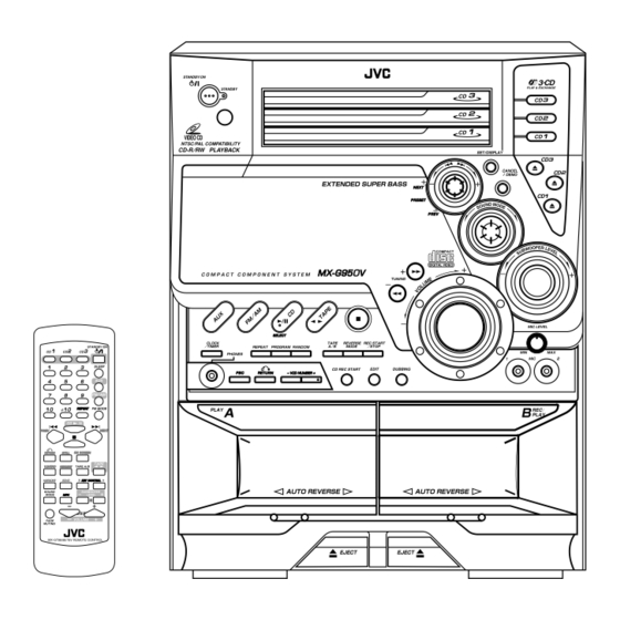
COMPACT COMPONENT SYSTEM
CA-MXG950V
CA-MXG850V / CA-MXG880V
CA-MXG750V
CA-MXG950V
CA-MXG850V
CA-MXG880V
INSTRUCTIONS
CA-MXG750V
COMPACT
DIGITAL AUDIO
DIGITAL VIDEO
For Customer Use:
Enter below the Model No. and Serial
No. which are located either on the rear,
bottom or side of the cabinet. Retain this
information for future reference.
Model No.
Serial No.
GVT0079-001B
[U, UN, US, UX]
COMPACT
Advertisement
Table of Contents

Related Manuals for JVC CA-MXG950V


Summary of Contents for JVC CA-MXG950V
- Page 1 COMPACT COMPONENT SYSTEM CA-MXG950V CA-MXG850V / CA-MXG880V CA-MXG750V CA-MXG950V INSTRUCTIONS CA-MXG850V CA-MXG880V COMPACT DIGITAL VIDEO For Customer Use: Enter below the Model No. and Serial No. which are located either on the rear, bottom or side of the cabinet. Retain this information for future reference.
- Page 2 Warnings, Cautions and Others Caution — STANDBY/ON button! Disconnect the mains plug to shut the power off completely. The STANDBY/ON button in any position does not disconnect the mains line. The power can be remote controlled. – G-1 –...
- Page 3 CAUTION To reduce the risk of electrical shocks, fire, etc.: 1. Do not remove screws, covers or cabinet. 2. Do not expose this appliance to rain or moisture. CAUTION • Do not block the ventilation openings or holes. (If the ventilation openings or holes are blocked by a newspaper or cloth, etc., the heat may not be able to get out.) •...
-
Page 4: Important For Laser Products
DANGER: Invisible laser radiation when open and interlock failed or defeated. AVOID DIRECT EXPOSURE TO BEAM. 15 cm 1 cm 15 cm CA-MXG950V CA-MXG880V CA-MXG850V CA-MXG750V – G-3 – ADVARSEL: Usynlig laser- VARO: Avattaessa ja suo- VARNING: Osynlig laser- stråling ved åbning, når jalukitus ohitettaessa olet strålning när denna del är... - Page 5 Introduction We would like to thank you for purchasing one of our JVC products. Before operating this unit, read this manual carefully and thoroughly to obtain the best possible performance from your unit, and retain this manual About This Manual This manual is organized as follows: •...
-
Page 6: Table Of Contents
Contents Location of the Buttons and Controls ... 3 Remote Control ... 3 Front Panel ... 4 Getting Started ... 6 Supplied Accessories ... 6 Putting the Batteries into the Remote Control ... 6 Connecting Antennas ... 6 Connecting Speakers ... 7 Surround Speakers ... -
Page 7: Location Of The Buttons And Controls
Location of the Buttons and Controls Remote Control When using the remote control, point it at the remote sensor on the front panel. Remote Control 1 Disc number buttons (CD1, CD2, and CD3) (15 – 16, 22) Pressing one of these buttons also turns on the unit. 2 Number buttons (13, 15 –... -
Page 8: Front Panel
Become familiar with the buttons and controls on your unit. Front Panel Front Panel Notes: 1. CA-MXG750V: ACTIVE BASS EXTENSION CA-MXG950V/850V/880V: EXTENDED SUPER BASS 2. CA-MXG750V: BASS LEVEL CA-MXG950V/850V/880V: SUBWOOFER LEVEL 3. All illustrations in this manual will be based on CA-MXG950V/880V/850V – 4 – Continued... - Page 9 Display Window See pages in the parentheses for details. Front Panel 1 Disc trays 2 STANDBY/ON button and STANDBY lamp (10, 30, 31) 3 Remote sensor 4 PRESET +/– NEXT/PREV control 4 / ¢ (reverse search/forward search) (10, 12 – 13, 15 –...
-
Page 10: Getting Started
Getting Started Supplied Accessories Make sure that you have all the following items. The number in the parentheses indicates the quantity of the pieces supplied. • AM loop antenna (1) • FM antenna (1) • Remote control (1) • Batteries (2) •... -
Page 11: Connecting Speakers
• Make sure the antenna conductors do not touch any other terminals and connecting cords. • Keep the antennas away from metallic parts of the unit, connecting cords, and the AC power cord. Connecting Speakers For Models CA-MXG950V/880V/850V Vinyl-covered wire (not supplied) Speaker cords (red/black) -
Page 12: Surround Speakers
Connecting Speakers For Model CA-MXG750V Speaker cords (red/black) Speaker cords (red/black) Left Right speaker speaker Open the speaker terminals on the rear of the unit. Insert the end of the speaker cord into the terminal. Match the polarity (colours) of the speaker terminals: Red (+) to red (+) and black (–) to black (–). -
Page 13: Connecting Other Equipment
Connecting Other Equipment You can connect both analog and digital equipment. • DO NOT connect any equipment while the power is on. • DO NOT plug in any equipment until all connections are complete. To connect an analog component Be sure that the plugs of the audio cords are coloured: White plugs and jacks are for left audio signals, and red ones for right audio signals. -
Page 14: Common Operations
Common Operations Turning On or Off the Power To turn on the unit, press STANDBY/ON so that the STANDBY lamp goes off. To turn off the unit (on standby), press STANDBY/ON again so that the STANDBY lamp lights up. • A little power is always consumed even while the unit is on standby. -
Page 15: Adjusting The Volume
Adjusting the Volume You can adjust the volume level only while the unit is turned on. The volume level can be adjusted in 32 steps (VOL MIN, VOL 01 — VOL 30 and VOL MAX). Turn VOLUME + / – clockwise (+) to increase the volume or counterclockwise (–) to decrease it. -
Page 16: Creating Your Own Sound Mode - Manual Mode
STADIUM: Adds clarity and spreads the sound, like in an outdoor stadium. SEA (Sound Effect Amplifier) modes: ROCK: Boosts low and high frequency. Good for acoustic music. POP: Good for vocal music. CLASSIC: Good for classical music. Manual modes: MANUAL 1/2/3: Your individual mode stored in memory. -
Page 17: Listening To Fm And Am Broadcasts
Listening to FM and AM Broadcasts Tuning in a Station Press FM/AM. The unit automatically turns on and tunes in the previously tuned station (either FM or AM). • Each time you press the button, the band alternates between FM and AM. Start searching for stations. -
Page 18: Playing Back Cds (Cd/Cd-R/Cd-Rw)
Playing Back CDs (CD/CD-R/CD-RW) This unit has been designed to playback the following CDs: • CD (Audio CD) • CD-R (CD-Recordable) • CD-RW (CD-ReWritable) Continued use of irregular shape CDs (heart-shape, octagonal, etc.) can damage the System. General Notes In general, you will have the best performance by keeping your CDs and the mechanism clean. -
Page 19: Playing Back The Entire Discs - Continuous Play
Playing Back the Entire Discs — Continuous Play Load CDs. Press one of the disc number buttons (CD1, CD2 and CD3) for the disc you want to play. CD play starts from the first track of the selected disc and the disc number lamp starts flashing. Tracks of the currently playing disc (Track numbers exceeding 16 are not displayed.) Elapsed playing time... -
Page 20: Programming The Playing Order Of The Tracks - Program Play
Programming the Playing Order of the Tracks — Program Play You can arrange the order in which tracks play before you start playing. You can program up to 50 tracks. • To use Repeat play (see page 17) for Program play, press REPEAT after starting Program play. -
Page 21: Playing At Random - Random Play
Playing at Random — Random Play The tracks of all loaded CDs will play at random. • To use Repeat play for Random play, press REPEAT after starting Random play. Load CDs. • If the current playing source is not the CD player, press CD 3¥8 SELECT, then 7 before going to the next step. -
Page 22: Playing Back Video Cds
Playing Back Video CDs Selecting Video Output (PAL, MULTI, NTSC) You can set this setting in Standby mode. Before playing a VCD, use the buttons on the unit to select a video output mode to match your TV system. Video output is preset for PAL. Press and hold one of the disc number buttons (CD1, CD2 or CD3) for more than 2 sec. -
Page 23: Playing Video Cds With Pbc Function - Menu Play
Playing Video CDs with PBC Function — Menu Play This System provides Playback Control (PBC) which utilizes a procedure (menu selection) programmed in a video CD. The playback operation procedure may differ depending on the disc you use. For Menu Play, use the following buttons: On the unit: NEXT (¢) ... -
Page 24: Playing Video Cds Without Pbc - Continuous Play
Screen-saver • When a menu screen of a karaoke disc is displayed for a few minutes without any selection being made, it automatically starts from the first song. Reminder! Do not paused Video CD for more then 10 minutes to prevent screen burns. -
Page 25: Playing A Multiplex Sound Cd
The TV screen will show the following: VIDEO INTRO Press the number button for the video intro you want to select. Playback starts from the selected track. To stop and cancel the video intro play, press 7. Viewing the Highlights of a Video CD You can view highlight scenes of the selected track on a video CD only when PBC is off. -
Page 26: Mp3 Disc Playback
MP3 Disc Playback About MP3 discs An MP3 disc can have several folders (albums). Tracks are contained within the albums. The player will only recognize up to 64 albums. Total number of tracks recognizable is 255. Recording your own MP3 discs •... -
Page 27: Playing Back Tapes
Playing Back Tapes You can playback type I, type II and type IV tapes without changing any settings. Playing Back a Tape Press EJECT (0) for the deck you want to use. For Deck A Put a cassette in with the exposed part of the tape down. -
Page 28: Recording
Recording IMPORTANT: • It may be unlawful to record or play back copyrighted material without the consent of the copyright owner. • The recording level is automatically set correctly, so it is not affected by the VOLUME, the SUBWOOFER LEVEL, and the SOUND MODE controls. -
Page 29: Dubbing Tapes
To record on both sides — Reverse Mode Press REVERSE MODE so that the Reverse Mode indicator lights up — • When using Reverse Mode for recording, start recording in the forward (3) direction first. Otherwise, recording will stop when recording is done only on one side (reverse) of the tape. -
Page 30: Auto Edit Recording
Auto Edit Recording By using Auto Edit Recording, you can record the CD tracks to fit the tape. Auto Edit Recording makes a program by selecting the CD tracks in numerical order. However, to prevent the end of the last track on the front side from being cut off, the last track is selected so as to fit on the remaining tape length. -
Page 31: Using The Microphones
Using the Microphones You can enjoy singing along (Karaoke) and microphone mixing using two microphones. • MIC LEVEL adjustment is valid for both microphones connected MIC 1 and MIC 2 jacks. IMPORTANT: • Always set MIC LEVEL to MIN when connecting or disconnecting the microphone. -
Page 32: Recording Your Singing
When finished singing Restore the stereo effect by pressing MPX until “NORMAL” appears on the display. Recording Your Singing You can adjust the music key using the remote control. Follow the steps in “Singing Along with Multiplex Karaoke Discs (MPX)” in page 27. Follow the steps in “Recording a Tape on Deck B”... -
Page 33: Using The Timers
Using the Timers There are three timers available — Daily Timer, Recording Timer and Sleep Timer. Before using the timers, you need to set the clock built in the unit. (See page 10.) Using Daily Timer With Daily Timer, you can wake to your favorite music or radio program. - Page 34 Turn 4 / ¢ to select the source to play, then press SET/DISPLAY. • The source changes as follows: TUNER FM TUNER AM TAPE – CD TUNER FM: tunes into a specified preset FM station. = Go to step 6. TUNER AM: tunes into a specified preset AM station.
-
Page 35: Using Recording Timer
Using Recording Timer With Recording Timer, you can make a tape of a radio broadcast automatically. You can set the timer whether the system is on or off. How Recording Timer works The unit automatically turns on, tunes into the specified station, sets the volume level to “VOL MIN,”... -
Page 36: Using Sleep Timer
To turn on or off Recording Timer after its setting is done 1 Press CLOCK/TIMER repeatedly until “REC” appears on the display. 2 To turn off the Recording Timer, press CANCEL/DEMO. The REC (Recording Timer) indicator goes off from the display. The Recording Timer is cancelled, but the setting for the Recording Timer remains in memory. -
Page 37: Maintenance
Maintenance To get the best performance of the unit, keep your discs, tapes, and mechanism clean. Handling discs • Remove the disc from its case by holding it at the edge while pressing the center hole lightly. • Do not touch the shiny surface of the disc, or bend the disc. -
Page 38: Troubleshooting
Troubleshooting If you have a problem with your unit, check this list for a possible solution before calling for service. If you cannot solve the problem from the hints given here, or the unit has been physically damaged, call a qualified person, such as your dealer, for service. -
Page 39: Specifications
Specifications CA-MXG950V (Silver Colour) Amplifier section Output Power SUBWOOFERS: 88 W per channel, min. RMS, both channels driven into 6 at 63 Hz with no more than 0.9% total harmonic distortion. MAIN SPEAKERS: 28 W per channel, min. RMS, both channels driven into 6 at 1 kHz with no more than 0.9% total harmonic distortion. - Page 40 Mains (AC) Line Instruction (not applicable for Europe, U.S.A., Canada, Australia, and U.K.) IMPORTANT for mains (AC) line BEFORE PLUGGING IN, do check that your mains (AC) line voltage corresponds with the position of the voltage selector switch provided on the outside of this equipment and, if different, reset the voltage selector switch, to prevent from damage or risk of fire/electric shock.
-
Page 41: Speaker System
INSTRUCTIONS SPEAKER SYSTEM SP-MXG950V Consists of SP-XG950V, SP-WG950V and SP-XSG950V MANUAL DE INSTRUCCIONES: SISTEMA DE ALTAVOCES INSTRUÇÕES: SISTEMA DE ALTIFALANTES This system consists of the following systems: Este sistema se compone de los cuatro siguientes: Este equipamento compõe-se dos seguintes sistemas: MAIN SPEAKER SYSTEM : SP-XG950V SUBWOOFER : SP-WG950V SURROUND SPEAKER SYSTEM : SP-XSG950V... - Page 42 Antes de desfrutar este sistema, leia atentamente as instruções que o acompanham, de modo a assegurar-se da obtenção do melhor desempenho possível. Caso surjam dúvidas concernentes a este sistema, consulte o seu agente JVC. 感谢您惠购 JVC 扬声器。 在开始使用之前,请您仔细阅读本使用说明书,以确保您获得扬声 器的最佳性能。如有疑问,请与 JVC 代理销售商联系。...
- Page 43 MAIN SPEAKER SYSTEM : SP-XG950V SUBWOOFER : SP-WG950V MAIN SPEAKER SYSTEM : SP-XG950V SUBWOOFER : SP-WG950V SISTEMA DE ALTAVOZ PRINCIPAL : SP-XG950V SUBWOOFER : SP-WG950V SISTEMA DE ALTO-FALANTE PRINCIPAL : SP-XG950V SUBWOOFER : SP-WG950V SPEAKER FOR A/V COMBINATION SP-XG950V and SP-WG950V have a magnetically-shielded design for placement adjacent to TV’s and monitors without causing color aberrations.
- Page 44 放大器输出端子 CONNECTION • DON’T use other amplifier to operate this speaker system except for CA-MXG950V. • Turn off power to the whole system before connecting the speak- ers to the amplifier. • The maximum power handling capacity of the SP-XG950V main speaker is 50 W/Subwoofer is 130 W.
- Page 45 El diseño y las especificaciones están sujetos a cambio sin previo aviso. LIGAÇÃO • NÃO use outro amplificador para operar este sistema de altifalantes à excepção do CA-MXG950V. • Desligue a alimentação de todo o sistema antes de iniciar as ligações dos altifalantes ao amplificador.
- Page 46 接线 • 请勿使用其他放大器操作 CA-MXG950V 以外的扬声器系统。 • 要将扬声器连接到放大器时,须关掉全装置系统的电源。 • SP-XG950V 主扬声器的最大功率储备容量为 50 W(瓦),副低音 喇叭的为 130 W(瓦)。过大的输入,将造成异常噪声,甚至损坏扬 声器。当下列信号输入扬声器时,即使该信号低于最大容许输入,仍 有可能造成过载而烧毁扬声器导线,故请预先调低放大器的音量控 制,以籍安全。 1)在 FM 调谐中产生的噪声。 2)磁带录音机的快进模式中产生的含有高频成分的高电平信号。 3)开关其它组成部分电源时产生的喀嗒噪声。 4)接通着电源进行接线或断线时产生的喀嗒噪声。 5)接通着电源更换卡盘时产生的喀嗒噪声。 6)操作放大器开关时产生的喀嗒噪声。 7)连续的高频率振荡或高音调电子装置产生的乐器声。 8)使用麦克风时发生的啸声。 小心 切勿拖拉放在地板或桌面上的扬声器。 否则,各扬声器底部的四个支脚可能会剥离或脱落。 规格 类型 ∶ 3 路 3 单元低音反射型 主扬声器带 2 个分离的重低音喇叭...
- Page 47 SURROUND SPEAKER SYSTEM SURROUND SPEAKER SYSTEM : SP-XSG950V SISTEMA DE ALTAVOCES PERIMÉTRICOS : SP-XSG950V SISTEMA DE COLUNAS SURROUND : SP-XSG950V HOW TO INSTALL SURROUND SPEAKERS • This equipment is not magnet-proof. If it is placed near a TV set, color on a TV screen may become uneven. If the case of installation, therefore, locate it at sufficient distance from the TV set.
- Page 48 Amplifier Connection Conexión del amplificador Ligação do amplificador 放大器连接 r C*U U UL « qO u « Surround speakers Altavoces peromètricos Colunas surround 环绕扬声器 CONNECTION A pin plug is attached to the tip of the speaker cord. If the speaker connection terminal on the amplifier to which the speaker is to be connected is a pin jack, connect the left-hand speaker’s lead to the left terminal, and the right-hand speaker’s lead to the right terminal.
- Page 49 CONEXIÓN Una clavija monopolar está fijada al extremo del cordón del altavoz. Si el terminal de conexión para altavoz en el amplificador al cual se conectará el altavoz es un jack monopolar, conecte el cable del altavoz izquierdo al terminal izquierdo, y el cable de altavoz derecho al terminal derecho.
- Page 50 连接 扬声器软线尖头装有插脚式插头。如果放大器上的用以连接扬声器 的扬声器连接端子为插脚式插孔,将左侧扬声器导线连接到左端 子,将右侧扬声器导线连接到右端子。 • 在将扬声器连接到放大器上之前,要关断所有设备的电源。 • SP-XSG950V 的额定阻抗为 16Ω(欧姆)。请将它们连接到带 有 16Ω(欧姆)扬声器的负荷阻抗的放大器。 • 最大储备功率如规格中所示。 过大的功率输入扬声器将会造成异常噪声,甚至可能导致扬声器 损坏。 下述情况可能会引起扬声器超载。此时,务请预先调低放大器的 音量。 1) 在作 FM 调谐中,发生噪声。 2) 磁带录音机的快进绕模式中产生的含有高频部分的高电平信 号。 3) 开关其他组成机电源时产生的喀嗒噪声。 4) 接通着电源的组成机间的接线或拆卸接线时产生的喀嗒噪声。 5) 接通着电源更换卡声时产生的喀嗒噪声。 6) 操作放大器开关时产生的喀嗒噪声。 7) 连续的高频振荡音或高音电子乐器产生的声音。 8) 使用麦克风时出现啸叫声或反馈声 规格 SP-XSG950V 类型 ∶...
- Page 52 VICTOR COMPANY OF JAPAN, LIMITED EN. SP. PR. CH. AR. 0202NSMPRIJEM...
- Page 53 JVC dealer. Le estamos muy agradecidos por haber adquirido estos altavoces de JVC. Antes de utilizarlos, sirvase leer las instrucciones detenidamente a fin de obtener el mejor rendimiento posible. Si tiene alguna pregunta, acuda a su agente de JVC.
- Page 54 SPEAKER FOR A/V COMBINATION SP-XG850V/SP-XG880V and SP-WG850V/SP-WG880V have a magnetically-shielded design for placement adjacent to TV’s and monitors without causing color aberrations. However, color may be affected as a result of how the speaker system is installed. Therefore, be careful of the following: 1.
- Page 55 Connection Conexión Ligaçao 接线 qO u « Right Subwoofer Subwoofer derecho Right Main Speaker Subwoofer direito Altavoz principal derecho 右置副低音扬声器 Altifalante principal direito 右置主扬声器 Black Negra Preto 黑色 Rojo Vermelho 红色 Blue Azul Azul 蓝色 Black Negra Preto 黑色 Amplifier output terminals Terminales de salida de amplificador Terminais de saida do amplificador 放大器输出端子...
- Page 56 CONEXIÓN • NO utilice ningún otro amplificador para operar este sistema de altavoces excepto CA-MXG850V/CA-MXG880V. • Desactive la alimentación de todo el sistema antes de conectar los altavoces al amplificador. • La capacidad máxima de potencia del altavoz principal del SP- MXG850V/SP-MXG880V es de 40 W y la del altavoz de subgraves es de 120 W.
- Page 57 接线 ・ 请勿使用其他放大器操作 CA-MXG850V/CA-MXG880V 以外 的扬声器系统。 ・要将扬声器连接到放大器时,须关掉全装置系统的电源。 ・SP-MXG850V/SP-MXG880V 主扬声器的最大功率储备容量为 40 W(瓦),副低音喇叭的为 120 W(瓦)。过大的输入,将造 成异常噪声,甚至损坏扬声器。当下列信号输入扬声器时,即使 该信号低于最大容许输入,仍有可能造成过载而烧毁扬声器导 线,故请预先调低放大器的音量控制,以籍安全。 1)在 FM 调谐中产生的噪声。 2)磁带录音机的快进模式中产生的含有高频成分的高电平信号。 3)开关其它组成部分电源时产生的喀嗒噪声。 4)接通着电源进行接线或断线时产生的喀嗒噪声。 5)接通着电源更换卡盘时产生的喀嗒噪声。 6)操作放大器开关时产生的喀嗒噪声。 7)连续的高频率振荡或高音调电子装置产生的乐器声。 8)使用麦克风时发生的啸声。 小心 切勿拖拉放在地板或桌面上的扬声器。 否则,各扬声器底部的四个支脚可能会剥离或脱落。 规格 类型 ∶ 3 路 3 单元低音反射型 主扬声器带 2 个分离的重低音喇叭 (防磁型) 扬声器...
- Page 58 VICTOR COMPANY OF JAPAN, LIMITED EN. SP. PR. CH. AR. 0202NSMPRIJEM...
- Page 59 JVC dealer. Le estamos muy agradecidos por haber adquirido estos altavoces de JVC. Antes de utilizarlos, sirvase leer las instrucciones detenidamente a fin de obtener el mejor rendimiento posible. Si tiene alguna pregunta, acuda a su agente de JVC.
- Page 60 SPEAKER FOR A/V COMBINATION SP-MXG750V has a magnetically-shielded design for placement adjacent to TV’s and monitors without causing color aberrations. However, color may be affected as a result of how the speaker system is installed. Therefore, be careful of the following: 1.
- Page 61 Connection Conexión Ligaçao 接线 qO u « Black Negra Preto 黑色 Rojo Rojo Vermelho Vermelho 红色 红色 Left Speaker Right Speaker Altavoz izquierdo Altavoz derecho Altifalante esquerdo Altifalante direito 左置扬声器 右置扬声器 CONNECTION • DON’T use other amplifier to operate this speaker system except for CA-MXG750V.
- Page 62 CONEXIÓN • NO utilice ningún otro amplificador para operar este sistema de altavoces excepto CA-MXG750V. • Desactive la alimentación de todo el sistema antes de conectar los altavoces al amplificador. • La potencia máxima admisible del SP-MGX750V es de 100W. En casos donde las señales descritas más abajo se apliquen a los altavoces, aunque las mismas resulten menores que la entrada máxima permisible, pueden causar una sobrecarga y...
- Page 63 接线 ・请勿使用其他放大器操作 CA-MXG750V 以外的扬声器系统。 ・要将扬声器连接到放大器时,须关掉全装置系统的电源。 ・SP-MXG750V 的额定阻抗为 6Ω。请选择使用可以连接负载阻 抗为 6Ω 的扬声器系统的放大器。 ・ SP-MXG750V 的最大功率容量为 100W。过大的输入,将造成 异常噪声,甚至损坏扬声器。当下列信号输入扬声器时,即使该 信号低于最大容许输入,仍有可能造成过载而烧毁扬声器导线, 故请预先调低放大器的音量控制,以籍安全。 1)在 FM 调谐中产生的噪声。 2)磁带录音机的快进模式中产生的含有高频成分的高电平信号。 3)开关其它组成部分电源时产生的喀嗒噪声。 4)接通着电源进行接线或断线时产生的喀嗒噪声。 5)接通着电源更换卡盘时产生的喀嗒噪声。 6)操作放大器开关时产生的喀嗒噪声。 7)连续的高频率振荡或高音调电子装置产生的乐器声。 8)使用麦克风时发生的啸声。 小心 切勿拖拉放在地板或桌面上的扬声器。 否则,各扬声器底部的四个支脚可能会剥离或脱落。 规格 类型 ∶ 3 路 3 单元低音反射型 (防磁型) 扬声器 低音喇叭...
- Page 64 VICTOR COMPANY OF JAPAN, LIMITED EN. SP. PR. CH. AR. 0202NSMPRIJEM...