
Related Manuals for Jøtul F 55 Carrabassett


Summary of Contents for Jøtul F 55 Carrabassett
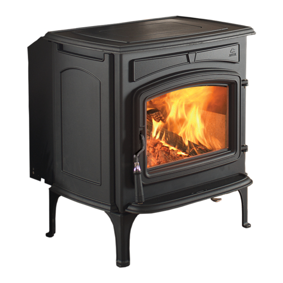
- Page 1 Jøtul F 55 Carrabassett Installation and Operating Instructions for USA and Canada Keep these instructions for future reference.
-
Page 2: Table Of Contents
Mobile Home Requirements ..........10 aux inspections d’installations dans votre région. 4.0 Clearances to Combustibles Floor Protection ..............11 Jøtul F 55 Carrabassett 4.2 Clearances to Walls and Ceilings ........11 Using Shields to Reduce Clearances ........11 Accessories 4.4 Alcove Installation ..............12 Fireplace Clearances, Mantel and Trim ........ - Page 3 Always consult your local building inspector or climate, environment, operation, and chimney function. authority having jurisdiction to determine what The Jøtul F 55 Carrabassett wood stove is only listed to regulations apply in your area. burn solid wood only. Do not burn any other fuels.
-
Page 4: Safety Notices
139473_A 9/11/12 Safety Notices • Burn solid wood fuel only • We recommend that this stove be installed by a professional solid fuel technician or • Do not use chemicals or fluids to start the fire. that you consult one if you do the work Do not burn garbage or flammable fluids. yourself. Also, consult your insurance • Read this entire manual before you install company regarding any other specific and use your new room heater. -
Page 5: Installation
139473_A 9/11/12 1.0 Installation 27 1/4” (692 mm) If this solid fuel room heater is not properly installed, a house fire may result. For your safety, follow the installation directions. Contact the local building or fire officials about restrictions and installation inspection requirements in your area. 15 1/2”... -
Page 6: Flue Collar Installation
139473_A 9/11/12 1.2 Flue Collar Orientation The Flue Collar is oriented in the Top Exit position. To change orientation to Rear Exit: 1. Twist and remove the perforated cut-out section from the top edge of the rear shroud. 2. Use a 10 mm open end wrench or socket wrench to remove the two M6 x 12 bolts that attach the flue collar to the stove. -
Page 7: Chimney Requirements
139473_A 9/11/12 2.0 Chimney Requirements 2.1 Masonry Chimneys There are two types of approved chimneys: 1. A code-approved masonry chimney with a ceramic tile Follow these guidelines when installing the Jøtul F 55 into or listed steel flue liner. a masonry fireplace: 2. -
Page 8: Chimney Height
139473_A 9/11/12 2.3 Chimney Height 2’ The chimney must be at least 3 feet (92 cm) higher than 61 cm the highest point where it passes through the roof and at 10’ 3’ 305 cm 91.5 cm least 2 feet (61 cm) higher than the highest part of the roof or structure that is within 10 feet (3.05 m) of the chimney, measured horizontally. -
Page 9: Connecting To The Chimney
139473_A 9/11/12 In Canada 3.2 Hearthmount into a Masonry The installation must conform to CAN/CSA-B365, Fireplace Installation Code for Solid Fuel Burning Appliances and Equipment. Before proceeding be sure to consult your local The Jøtul F 55 may be installed into a masonry fireplace building inspector. -
Page 10: Prefabricated Chimneys
139473_A 9/11/12 3.4 Mobile Home Installation The cross-sectional area of the flue of a chimney with one or more walls exposed to the outside below the roofline The Jøtul F 55 is approved for installation in manufactured may be no more than two times the cross-sectional area of mobile homes provided the following requirements are the stove flue collar. -
Page 11: Clearances To Combustibles
139473_A 9/11/12 4.0 Clearance to Combustibles 4.1 Floor Protection The Jøtul F 55 requires one of the following forms of hearth protection if not installed directly on concrete poured on 2” earth: 2” 1) Any UL, ULC, or Warnock Hersey Listed Type 1 hearth board. 2) Any noncombustible material. -
Page 12: Alcove Installation
139473_A 9/11/12 19” 8” (203 mm) (483 mm) Maximum Maximum 48” 48” (1219 mm) (1219 mm) 6” 6” 16” 16” (152 mm) (152 mm) (406 mm) (406 mm) 39 1/2” (1003 mm) 59 1/2” (1511 mm) Figure 11. Alcove with Unprotected Walls. Figure 12. -
Page 13: Clearance Diagrams
139473_A 9/11/12 4.6 Jøtul F 55 Carrabassett Clearance Specifications PROTECTED WALLS UNPROTECTED WALLS PER NFPA211 OR CAN/CSA -B365-M93 SIDE REAR CORNER SIDE REAR CORNER Single Wall Connector 14” / 356 mm 18” / 457 mm 12” / 305mm 12” / 305 mm 8” / 203 mm 7.5”... -
Page 14: Operation
139473_A 9/11/12 5.0 Operation WARNING ALWAYS WEAR STOVE GLOVES WHILE TENDING THE FIRE. NEVER ALLOW THE FIRE TO REST DIRECTLY ON THE GLASS. KEEP THE LOGS SPACED AT LEAST ONE INCH FROM Please read the following section before building the first THE GLASS TO ALLOW FOR PROPER AIR FLOW WITHIN THE fire in your new Jøtul F 55. STOVE. AVOID STRIKING THE GLASS WITH LOGS. OPERATE THIS STOVE ONLY WITH THE FRONT DOOR 5.1 Use Solid Wood Fuel Only FULLY CLOSED OR FULLY OPEN WITH THE OPTIONAL This stove is designed to burn natural wood only. Wood SPARK SCREEN IN PLACE. OPERATION WITH THE DOOR that has been air-dried for a period of 6 to 14 months will PARTIALLY OPEN MAY RESULT IN OVER-FIRING. IF THE... -
Page 15: Air Control Settings
139473_A 9/11/12 5.4 Air Control / Blower Settings Break-in Odors: It is normal for a newly-painted Use the following guide for best performance. stove to emit odor and smoke during the first Burn Rate Air Control Setting Blower Speed few fires, and these may set off smoke alarms. Min. -
Page 16: Adding Fuel
139473_A 9/11/12 WARNING: NEVER OVER-FIRE THE STOVE. IF ANY PART OF THE 5.9 Creosote Formation and the STOVE OR CHIMNEY GLOWS, YOU ARE OVER-FIRING. Need for Removal A HOUSE FIRE OR SERIOUS DAMAGE TO THE STOVE OR CHIMNEY COULD RESULT. IF THIS CONDITION When wood is burned slowly, it produces tar and other OCCURS, IMMEDIATELY CLOSE THE AIR CONTROL. vapors that combine with moisture to form creosote. Creosote vapors condense in the relatively cool chimney flue, and creosote residue accumulates on the flue lining. -
Page 17: Maintenance
139473_A 9/11/12 6.0 Maintenance 6.1 Door Latch Adjustment 6.2 Glass Care Over time, as the door gasket becomes compressed, it may Cleaning be necessary to adjust the door latch in order to maintain the integrity of the door seal. To check the seal of the front On occasion it will be necessary to clean the carbon deposits door, close and latch the door on a dollar bill and slowly try and fly ash off of the glass. -
Page 18: Gasket Replacement
139473_A 9/11/12 6.4 Gasket Replacement 1. Use pliers and a putty knife to remove the old gasket and adhesive from the door. 2. Thoroughly clean the channel with a wire brush. 3. Apply a small bead of cement to the channel. 4. - Page 19 139473_A 9/11/12 This page is intentionally blank.
-
Page 20: Appendix
139473_A 9/11/12 7.0 Appendix 2. Attach the Air Deflector: See figs. 19 and 21 /#3. Use pliers to bend the deflector tabs at the perforation lines as shown. Attach the deflector to the interior side of the rear shroud using two #8 X 12 sheet metal screws from the exterior side. 7.1 Optional Blower 156431 BEND Tools Required... - Page 21 139473_A 9/11/12 Figure 21. Blower Parts Identification. Capture the bracket between the leg nut and the Lower Air Deflector bracket nut. Snapstat Blower Assembly Snapstat Bracket Blower Mounting Bracket Air Deflector M6 Flange Hex Nut (3) M6 Wingnut (2) Control Box Assembly 10.
-
Page 22: Outside Air Kit Installation
139473_A 9/11/12 7.2 Outside Air Kit 157440 Contents: • Outside Air Manifold (fig. 23) Tools Required: • 13 mm socket driver or wrench • safety glasses • work gloves You will need to acquire the following additional components available at any hardware supplier: •... -
Page 23: Mobile Home Floor Bracket
139473_A 9/11/12 7.3 Mobile Home Floor Bracket Kit 157321 Contents: Floor Brackets , (2) 1. Determine the final location of the stove and use the levelling bolts to make the stove level and plumb. 2. Mount the floor brackets over levelling bolts at rear and front locations at opposite corners and secure each to the floor using an appropriate length lag screw. - Page 24 139473_A 9/11/12 Figure 25. F 55 Carrabassett Illustrated Parts...
-
Page 25: Illustrated Part List
139473_A 9/11/12 8.0 Jøtul F 55 Carrabassett Parts List Ashlip, MB / D&T 157348 Description Part Number Description Part Number Screw, Button Head Socket - M6 x 10 Blk 117978 Brick Retainer, Right 224113 Glass Clip w/Gasket, Top, Steel Stoves... -
Page 26: Warranty Statement
139473_A 9/11/12 9.0 Jøtul F 55 Carrabassett Product Limited Warranty Effective January 1, 2012 This warranty policy applies to wood-burning products identified by 4) Damage due to, or repair of, rust. Use of stove-top steamers may Jøtul trade names, as set forth below. - Page 27 139473_A 9/11/12 This page is intentionally blank.
- Page 28 139473_A 9/11/12 Quality Jøtul AS utilizes quality controls conforming to NS-EN ISO 9001 for product development, manufacturing, and distribution of stoves and fireplaces. This policy is intended to provide you with the peace of mind that the Jøtul product you purchase meets or exceeds current uniform standards for quality and safety - a continuation of the standards instituted at the company’s inception in 1853.