
Related Manuals for Invacare Auriga10


Summary of Contents for Invacare Auriga10
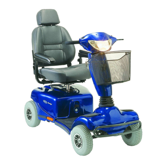
- Page 1 Invacare® Auriga & Auriga Invacare® Auriga & Auriga Scooter User Manual Scooter Bedienungsanleitung...
- Page 2 How can you get in touch with Invacare®? If you have any questions or need support, please contact your authorised Invacare® Dealer, who has the necessary know-how and equipment plus the special knowledge concerning your Invacare® product, and can offer you all-round satisfactory service. Should you wish to contact Invacare® directly, you can reach us in Europe at the following addresses and phone numbers.
- Page 3 Invacare® AS Grensesvingen 9 0603 Oslo Norge (Kundeservice): +47 - 22 57 95 10 Fax (Kundeservice): +47 - 22 57 95 01 Invacare® PORTUGAL Lda Rua Senhora de Campanhã, 105 4369-001 Porto PORTUGAL +351-225105946 Fax: +351-225105739 Invacare® n.v. Autobaan 14...
-
Page 4: Table Of Contents
Table of Contents Chapter Introduction Important symbols in this manual ...9 Type Classification and Area of Use ...10 Safety Notes General Safety Notes ...11 Safety information with regard to care and maintenance ...14 Safety Information on Electromagnetic Interference...15 Safety Information on Driving and Freewheel Mode...16 Key features Driving Before driving for the first time...19... - Page 5 6.1.2 Status display ...25 6.1.3 Battery charge display ...26 Driving the Scooter ...27 Diagnostics and Trouble Shooting...28 6.3.1 Diagnosing Faults ...29 Error Codes and Diagnostic Codes...30 Adjustment Options Adjusting the angle of the backrest ...33 Adjusting the position of the seat from front to back ...34 Adjusting the width of the armrests ...35 Releasing the seat so that it may rotated and/or removed ...36 Adjusting the height of the seat...37...
- Page 6 10.1.1.3 Removing a front wheel (3-Wheel Version)...53 10.1.1.4 Repairing the flat tyre ...54 11 Dismantling the scooter for transport 11.1 Removing the seat...56 11.2 Removing the batteries and the Drive Unit...57 11.2.1 Removing the batteries...57 11.2.2 Removing the Drive Unit...58 12 Technical Specifications 13 Inspections Performed...
-
Page 7: Introduction
The decision whether the model is suitable for the user may only be taken by medical specialists with appropriate aptitude. Invacare® or their statutory representatives can accept no liability in cases in which the mobility product has not been adapted to suit the user's handicaps. - Page 8 This manual contains copyrighted information. It may not be reproduced or copied in whole or in part without the prior written consent of Invacare® or its authorised representative. It may also contain information that pertains to models sold only in certain countries. In this case the information will be clearly marked as pertaining to a particular country-specific version.
-
Page 9: Important Symbols In This Manual
Important symbols in this manual WARNING! This symbol warns you of danger! Always follow the instructions to avoid injury to the user or damage to the product! EXPLOSION HAZARD! This symbol warns you of an explosion hazard, which can be caused by excessive tyre pressure in a pneumatic tyre! Always follow the instructions to avoid injury to the user or damage to the product! BURN HAZARD! -
Page 10: Type Classification And Area Of Use
Type Classification and Area of Use This vehicle has been classified as a mobility product in class C (for outdoor use). It has been successfully tested for its safety according to German and international standards. When equipped with an appropriate lighting system, the vehicle is suitable to be driven on public roads. -
Page 11: Safety Notes
Safety Notes READ WELL BEFORE OPERATION! General Safety Notes Danger of injury if this scooter is used in any other way than the purpose described in this manual! Adhere strictly to the instructions in this user manual! Danger of injury if the scooter is driven when your ability to drive is impaired by medication or alcohol! Never drive any vehicle under the influence of medication or alcohol! Danger of damage or injury if the scooter is accidentally set into motion! - Page 12 Danger of injury if the On/Off Button is pressed while the vehicle is in motion, due to it coming to an abrupt, sharp stop! If you have to brake in an emergency, simply release the drive lever, which will bring you to a halt! Only switch the vehicle off while in motion as a last resort! Danger of injury if the scooter is transported in another vehicle with the occupant seated in it!
- Page 13 Invacare® for this purpose! Have all electrical installations done by your authorised Invacare® Dealer! Danger of technical failure and injury if unauthorized spare parts and components are used! Only use original Invacare® spare parts, which have been approved for use with this vehicle!
-
Page 14: Safety Information With Regard To Care And Maintenance
Safety information with regard to care and maintenance Danger of accident and loss of guarantee if maintenance is insufficient! For reasons of safety and in order to avoid accidents which result from unnoticed wear, it is important that this electric vehicle undergoes an inspection once every year under normal operating conditions (see inspection plan contained in service instructions)! Under difficult operating conditions such as daily travel on steep slopes, or in the case of use in medical care cases with frequently changing wheelchair users, it would be expedient to... -
Page 15: Safety Information On Electromagnetic Interference
Safety Information on Electromagnetic Interference This electric vehicle was successfully tested in accordance with International standards as to its compliance with Electromagnetic Interference (EMI) Regulations. However, electromagnetic fields, such as those generated by radio and television transmitters, and cellular phones, can influence the functions of electric vehicles. -
Page 16: Safety Information On Driving And Freewheel Mode
Safety Information on Driving and Freewheel Mode Danger of injury if the vehicle tips over! Only ever negotiate gradients of up to the maximum defined in the Technical Specifications and only with the backrest in an upright position, and the seat lifter in the lowest position (if installed)! Only ever drive downhill at a maximum of 2/3rds of the top speed! Avoid abrupt braking or accelerating on gradients! - Page 17 Danger of injury if the vehicle tips over! (Continued) Never use the vehicle to transport more than one person! Do not exceed the maximum permissible load! When loading the vehicle, always distribute the weight evenly! Always try to keep the centre of gravity of the vehicle in the middle, and as close to the ground as possible! Note that the vehicle will brake or accelerate if you change the Driving Speed while it is in motion!
-
Page 18: Key Features
Key features 1) De-clutching lever 2) Release lever for swivelling and removing seat (under the seat on the right) 3) Release lever for seat sliding rail adjustment (under the seat on the right in the front) 4) Primary Charging Socket 5) Key switch (ON/OFF) 6) Throttle 7) Control panel... -
Page 19: Driving
Driving Before driving for the first time... Before you take your first trip, you should familiarise yourself well with the operation of the vehicle and with all operating elements. Take your time to test all functions and driving modes. NOTE: If installed, use the restraining systems (seat belts) each time you use the vehicle. -
Page 20: Taking Obstacles
Taking Obstacles Your Invacare® Auriga/Auriga CAUTION: Danger of Tipping Over! Never approach obstacles at an angle! Put your backrest into an upright position before climbing an obstacle! Driving up over an obstacle Approach the kerb or obstacle slowly head-on. Shortly... -
Page 21: Driving Up And Down Gradients
Driving up and down gradients The Invacare® Auriga/Auriga 4-Wheel Version (up to 150 kg payload): 3-Wheel Version (up to 120 kg payload): 3-Wheel Version (up to 150 kg payload): WARNING: Danger of tipping over! Only ever drive downhill at a maximum of 2/3rds of the top speed! -
Page 22: Parking And Stationary
Parking and stationary When parking your vehicle or if your vehicle is stationary for a prolonged period: Switch the vehicle's power system off (key switch). Activate the parking brake (if available). 4.4.1 Activating and de-activating the parking brake (option) Activating the brake Pull brake lever (1) and hold it. -
Page 23: Pushing The Scooter By Hand
Pushing the scooter by hand The motors of the scooter are equipped with automatic brakes, preventing the scooter from rolling away out of control when the power supply is switched off. When pushing the scooter, the magnetic brakes must be disengaged. Disengaging Motors Danger of the vehicle running away! When the motors are disengaged (for push operation), the electromagnetic motor brakes are... -
Page 24: The Control Panel
The Control Panel Control Panel layout Seat Lifter button (if installed) Battery charge indicator Hazard flashers Horn Right turn signal Driving speed adjustment Throttle lever Plug for external charger Reduced Speed Mode 10) Left turn signal 11) Lights... -
Page 25: Seat Lifter Button
6.1.1 Seat Lifter Button Press the button to activate the Seat Lifter (if installed). The LED above the button lights up. Raise or lower the seat using the throttle lever. Press the button once again to de-activate the Seat Lifter. The throttle lever reverts back to driving mode. -
Page 26: Battery Charge Display
6.1.3 Battery charge display All diodes lit: full driving range Only red and yellow diodes lit: decreased drive range. Charge batteries at end of journey. Only red diodes lit / flashing: battery reserve = very low drive range! Charge batteries immediately! NOTE Total discharge protection: After a certain drive time on reserve battery power the electronics switches off the drive automatically and the scooter will be immobile. -
Page 27: Driving The Scooter
Gently pull the right driving lever towards you to drive forwards. Gently pull the left driving lever towards you to drive backwards. NOTE The controller is programmed with standard values ex-works. Your Invacare® Dealer can program it to fit your requirements. NOTE: To brake quickly, simply let go of the driving lever. -
Page 28: Diagnostics And Trouble Shooting
Diagnostics and Trouble Shooting The electronics system provides diagnostics information to assist technicians to diagnose and correct faults within the scooter system. The existence of a fault will cause the status light to flash in bursts, separated by a pause. The nature of the fault is indicated by the number of flashes in each burst, also referred to as the Flash Code. -
Page 29: Diagnosing Faults
Check that all cables are connected correctly. If only the leftmost diode of the battery charge display is PERMANENTLY ON Contact your authorised Invacare® Dealer If the leftmost diode of the battery charge display is FLASHING Count the number of flashes and refer to the next section. -
Page 30: Error Codes And Diagnostic Codes
Error Codes and Diagnostic Codes Number of Fault flashes Battery needs charging Battery voltage too low Lifter raised Battery voltage too high Impact on Scooter Will drive Battery charge is running low. Recharge the batteries as soon as possible. Drive inhibited Battery charge is empty. - Page 31 The controller has detected a short- circuited motor. Check the cable harness for short and check the motor: Contact your authorised Invacare® Dealer. Check that the declutching lever is in the engaged position. The park brake coil or wiring is faulty.
- Page 32 Number of Fault flashes Other Internal Errors Impact on Scooter Drive inhibited Contact your authorised Invacare® Dealer. Notes...
-
Page 33: Adjustment Options
Adjustment Options Adjusting the angle of the backrest The backrest is held in place by a metal plate on each side. Each plate has 4 holes that are used to set the backrest to different angles. This is done by selecting different combinations of holes. Requirements: Allen key, 4 mm Spanner, 10 mm... -
Page 34: Adjusting The Position Of The Seat From Front To Back
Adjusting the position of the seat from front to back The lever for adjusting the seat back and forth is located under the seat in the front on the right side. Pull the lever (1) to release the seat. Slide the seat forward or backward to the desired position. -
Page 35: Adjusting The Width Of The Armrests
Adjusting the width of the armrests The knobs to release the armrests are located in the back, under the seat (1). Turn the knobs to release the armrests. Adjust the armrests to the desired width. Retighten the knobs. -
Page 36: Releasing The Seat So That It May Rotated And/Or Removed
Releasing the seat so that it may rotated and/or removed The seat can be rotated to the side to ease getting on and off of the scooter. In this position, the seat can also be removed. The lever for releasing the seat so that it can be rotated is located under the seat on the right (1). -
Page 37: Adjusting The Height Of The Seat
Adjusting the height of the seat The height of the seat can be adjusted to 43, 45, 47, or 49 cm. Requirements: 2 Spanners, 17 mm Remove the seat Remove the cover from the battery and motor compartment. Remove the bolt that hold the seat post, using the two spanners. - Page 38 NOTE Do not use the uppermost hole. In this position the seat is too low, and does not have enough clearance above the cowling. Adjust the seat height. Reposition the bolt and tighten.
-
Page 39: Electrical System
Electrical System Electronics Protection System The vehicle's electronics are equipped with an overload-protection system. If the motors are put under considerable strain for a longer period of time (for example, when driving up a steep hill) and especially when the ambient temperature is high, then the electronic system could overheat. -
Page 40: The Main Fuse
The entire electric system is protected against overload by two master fuses. The master fuses are mounted on the positive battery cables. NOTE A defective main fuse may be replaced only after checking the entire electric system. An Invacare® specialised dealer must perform the replacement. Batteries 8.2.1 What you need to know about batteries Power is supplied by two 12V gel batteries. - Page 41 The batteries cannot be overcharged with the specified charger. Please use only charging devices in Class 2. This class of chargers may be left unattended during charging. All charging devices which are supplied by Invacare® and comply with these requirements.
-
Page 42: Charging The Batteries
Danger of explosion and destruction of batteries if the wrong battery charger is used! Only ever use the battery charger supplied with your vehicle, or a charger that has been approved by Invacare®! Danger of electric shock and damage to the battery charger if it is allowed to get wet! - Page 43 The Invacare® Auriga/Auriga is equipped with an integrated charger. The socket for this charger is located on the front of the Battery and Motor Compartment Cover (1). To charge the scooter, you only need to connect it to a mains power supply using the cable supplied with the scooter.
- Page 44 The Invacare® Auriga/Auriga socket is on rear edge of the Control Panel (1). Connecting the charger Switch off the Scooter. Connect the battery charger to the Scooter. Connect the battery charger to the mains. Disconnecting the charger First disconnect the battery charger from the mains power supply.
-
Page 45: Removing And Fitting Batteries
8.2.3 Removing and fitting batteries WARNING: Danger of injury if the batteries are not handled correctly during assembly and maintenance work! New batteries should be installed by authorised technicians! Observe the warnings on the batteries! Take into account the heavy weight of the batteries! Only ever use the battery type defined in the technical specifications! Danger of fire and burns if battery terminals are short-circuited! DO NOT short-circuit battery terminals with a tool! -
Page 46: Removing The Batteries
8.2.3.1 Removing the batteries Requirements: Wrench 11 mm Remove the seat. Remove the battery and motor compartment cover. Disconnect the main cable harness. Open the belts that hold the batteries in place (1). Loosen battery clamp of the blue cable at the negative pole of the battery with the wrench and remove cable. -
Page 47: How To Handle Damaged Batteries Correctly
Only ever transport damaged batteries in an appropriate acid-resistant receptacle. Wash all objects that have come into contact with acid with lots of water. Disposing of dead or damaged batteries correctly Dead or damaged batteries can be given back to your dealer or directly to Invacare®. -
Page 48: Care And Maintenance
Care and maintenance NOTE: Have your vehicle checked once a year by an authorised Invacare® dealer in order to maintain it's driving safety and roadworthiness. Cleaning the vehicle When cleaning the vehicle, pay attention to the following points: Only use a damp cloth and gentle detergent. - Page 49 Once a year you should have your vehicle inspected and serviced by your authorised dealer. A complete checklist of necessary maintenance work can be found in the Service Manual, which can be obtained from Invacare®. Before every trip Before each trip...
-
Page 50: Repair Instructions
The following are instructions on repairs that can be performed by the user. For the specifications of spare parts please see "Technical Specifications" on page 59, or consult the Service Manual, available from Invacare®. In case you require assistance, please contact your Invacare® Dealer. 10.1... -
Page 51: Repairing A Flat Tyre (Pneumatic Tyres Type 260 X 85)
Remove the wheel, using the rubber hammer to coax it off of the axle by gently hitting it on the rear side. Having trouble removing the wheel? You might need to use a special tool. Please ask your authorized Invacare® Dealer for assistance. Re-assembly Re-assembly is done in reverse order. -
Page 52: Removing A Front Wheel (4-Wheel Version)
10.1.1.2 Removing a front wheel (4-Wheel Version) Requirements: Allen key 6 mm Rubber hammer Jack the vehicle up and place a block of wood underneath it to prop it up. Remove the nut that secures the wheel (1) using the 6 mm Allen key. -
Page 53: Removing A Front Wheel (3-Wheel Version)
10.1.1.3 Removing a front wheel (3-Wheel Version) Requirements: 2 Spanners, 17 mm Tilt the scooter over on it's side. Remove the bolts that hold the wheel (1) using the two spanners, then remove the wheel from the fork. Re-assembly Re-assembly is done in reverse order. Make sure that the wheel runs in the same direction it did before it was removed. -
Page 54: 10.1.1.4 Repairing The Flat Tyre
10.1.1.4 Repairing the flat tyre Requirements (General) Repair kit for inner tubes or an new inner tube. Talcum powder Socket spanner, 13 mm Requirements (3-Wheel Version - front wheel): Allen key, 6 mm Remove the valve cap. Let the air out of the tyre by pressing the pin in the centre of the valve in. - Page 55 Did the old inner tube get wet during repair? In case the old inner tube is to be repaired and used again, and it gets wet during repair, then it is easier to re-fit it if you powder it lightly with talcum powder. Place the rim halves in the tyre from the outside.
-
Page 56: Dismantling The Scooter For Transport
Dismantling the scooter for transport To dismantle the scooter for transport, proceed as follows: Remove the seat Remove the batteries Remove the drive unit The scooter is re-assembled in reverse order. 11.1 Removing the seat The lever for releasing the seat so that it can be rotated and removed is located under the seat on the right (1). -
Page 57: Removing The Batteries And The Drive Unit
11.2 Removing the batteries and the Drive Unit After removing the seat, proceed to remove the cover from the battery and motor compartment Cover. It is held in place with Velcro strips, so you only need to pull it upwards to remove it. 11.2.1 Removing the batteries For instructions on how to remove the batteries see chapter "Removing and fitting batteries"... -
Page 58: 11.2.2 Removing The Drive Unit
11.2.2 Removing the Drive Unit WARNING: Danger of injury by moving parts! The release lever for the drive unit is under tension! When releasing the drive unit be very careful not to get your hands or feet caught underneath the chassis of the scooter, or in between any moving parts! To release the drive unit, first you need to remove the securing pin that prevents the release lever from opening accidentally. -
Page 59: Technical Specifications
Technical Specifications 3-Wheel Version Electrical System Motor (6 km/h) 230 W Motor (10 km/h) 295 W Batteries Standard: 2 x 30 AH Option: 2 x 40 AH Main battery fuse (6 km/h) Main battery fuse 60 A (10 km/h) Charger On board, Input 230V AC, Output 3 A, 24V DC for 40 Ah batteries (external battery charger plug also... - Page 60 Dimensions Height Width Length (w/o bumpers and anti-tippers) Seat height (measured from the chassis, manually adjustable) Backrest height (w/o headrest) Backrest height (with headrest) Backrest angle (manually adjustable) Seat width Seat depth Armrest height Tyres Tyre pressure if fitted with pneumatic tyres 3-Wheel Version 4-Wheel Version...
- Page 61 3-Wheel Version Driving attributes Speed (6 km/h) 6.4 km/h (4 mph) Speed (10 km/h) 10 km/h (6,2 mph) Safe climbing capability up to 120 kg load: 12° (21%) up to 150 kg load: 10° (17%) Maximum obstacle height 8 cm Minimum turning radius 120 cm Range according to ISO...
-
Page 62: Inspections Performed
It is confirmed by stamp and signature that all jobs listed in the inspection schedule of the Service and Repair Instructions have been properly performed. The list of the inspection jobs to be performed can be found in the Service Manual which is available through Invacare®. Delivery Inspection...