Table of Contents
Advertisement
Quick Links
Advertisement
Table of Contents
Troubleshooting

Related Manuals for Intel Express 520T


Summary of Contents for Intel Express 520T
- Page 1 ® Intel Express 520T Switch User Guide 717285-002...
- Page 2 Copyright © 1999, Intel Corporation. All rights reserved. Intel Corporation, 5200 NE Elam Young Parkway, Hillsboro, OR 97124-6497 Intel Corporation assumes no responsibility for errors or omissions in this manual. Nor does Intel make any commitment to up- date the information contained herein.
-
Page 3: Table Of Contents
Removal of Intel Device View ........ - Page 4 Management using Intel Device View ........
- Page 5 Reporting the Problem to Intel Customer Support ........
- Page 7 And, the legal declarations and warnings A printed guide containing full instructions on how to install the switch and operate the switch using Intel Device View. Online, context-sensitive help text for each dialog box, providing in- formation about the permitted limits for the parameters used.
- Page 8 Electrostatic Sensitive Device This User Guide gives you instructions on how to use: • Intel Express 520T Switch • Intel Device View This User Guide is intended for personnel authorized to configure and manage local area networks. We assume that the person has an ad- vanced technical background within data communication and net- works.
- Page 9 Acronyms Access to submenus You access submenus using a menu hierarchy. These are shown by use of angle brackets and the courier typeface. For example, File>Configuration>Setup shows that to select the Setup sub- menu you must first click File and then Configuration. Address Resolution Protocol ASIC Application-Specific Integrated Circuit...
-
Page 11: Chapter 1 Intel Express 520T Switch
In this chapter Intel Express 520T Switch This chapter covers the following topics. Topic Introduction to the product Front Panel Rear Panel Installation See Page... -
Page 12: Introduction To The Product
Hardware features Intel Express 520T Switch Introduction to the product The Intel Express 520T Switch uses your existing network cables to integrate switching technology into your computer network. Each device in a workgroup or a network segment can communicate at a full wire-speed of 10Mbps or 100Mbps to provide: High-speed connectivity •... -
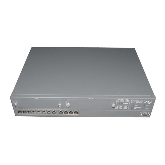
Page 13: Front Panel
The front panel of the switch is shown below: View of the front panel Intel Device View for Windows* 95, Windows* 98 and Windows NT* or Intel Device View for Web Adaptive forwarding mode... - Page 14 C H A P T E R 1 Front panel ports Slots for modules Front panel LED functions Buttons Intel Express 520T Switch These ports are on the front panel: Port Function CONSOLE port Connects a PC (running a VT100 emula-...
-
Page 15: Rear Panel
Rear Panel The rear panel has a cooling fan outlet and the main supply cable, so Introduction you should position the switch with the rear panel facing away from you. The rear panel of the switch is shown below: View of rear panel The switch’s rear panel has the following parts:... -
Page 16: Before Installation
Keep all the packaging materials in case you need to repack the switch. Read all labels and rating plates on the switch. If there is anything that you do not understand, or if any of the information provided does not appear to comply with your local or national rules and regulations, consult your dealer before proceeding with the installation. -
Page 17: Positioning And Installing The Switch
To ensure correct airflow, leave 100 mm (4 inches) free space on both sides and behind the switch. Do not allow the intake or outlet grills to become blocked. To install the switch in a desktop environment:... - Page 18 “Positioning and Installing the Switch”, p. Screw the mounting brackets securely to the equipment rack. If the switch is installed in a closed or multi-rack assembly, the oper- ating ambient temperature of the rack environment may be greater than the ambient temperature of the room.
-
Page 19: Installing A Module
If you remove the plate covering the slot on the front of the switch, Avoiding damage to the... -
Page 20: Connecting Other Devices
Only use unshielded cables when it is explicitly specified in the in- stallation manual of the device in question. Ports on the switch are wired MDI-X, so use the following cable: If you connect the switch to a... Workstation or server... - Page 21 C H A P T E R 1 Intel Express 520T Switch The RJ-45 ports on the front of the switch have the following pin as- RJ-45 connector pin signments: assignments Pin number To connect a workstation compatible with IEEE 802.3 (Ethernet Ver- Connecting a device to the sion 1.0 and 2.0) or a fast access device (such as a server) to the...
-
Page 22: Connecting The Power
Make sure that the brown wire is connected to the terminal marked with the letter L or colored red. If the switch is installed in a rack, make sure the rack’s power supply socket has a ground connection and the rack is connected to a branch supply or a power supply socket with a ground connection. -
Page 23: Power Up
Stage STATUS LED... If the Status LED remains red, then the switch has not started success- fully. Try to restart it; if the switch does not start, contact your dealer. Look at the other front panel LEDs during start-up and check that they are operating correctly. - Page 24 Port disabled by a hardware fault, or no solid hardware connected. Once the switch has started successfully, installation is complete and the switch is using its default setting (also known as default configu- ration): All ports are enabled. • •...
-
Page 25: Other Leds On The Front Panel
C H A P T E R 1 Intel Express 520T Switch Follow the instructions in Chapter 2 to change the configuration while the switch is operating. Other LEDs on the front panel There are three other LEDs and one button on the front panel that... - Page 26 C H A P T E R 1 Port Status button Intel Express 520T Switch To see the speed and duplex settings of all the ports, press the Port Status button. The function of the port LEDs changes for a period...
-
Page 27: Chapter 2 Intel Device View
In this chapter Intel Device View This chapter covers the following topics. Topic System Requirements Installation and Removal Using Intel Device View Installing and Managing Switches Device Tree Device View (Main Display) Explorer Diagnostics Window Trap Window System Window Errors Window... -
Page 28: System Requirements
Device View on the Web server Intel Device View System Requirements You need a PC with the following minimum requirements to run Intel Device View: • Microsoft Windows NT workstation or server, version 4.0, or Microsoft Windows 95 or Microsoft Windows 98. -
Page 29: Installation And Removal
Requirements for Intel Device View on the Web • client • To run Intel Device View with a plugin, the PC must be running HP Requirements for Intel OpenView* or Intel LANDesk Manager. Device View with plugin Installation and Removal... -
Page 30: Removal Of Intel Device View
Concept Intel Device View Click Install Windows and follow the on-screen instructions. When the installation is complete, Intel Device View will start auto- matically when “Launch Intel Device View” is selected. Click Install Web and follow the on-screen instructions. When the installation is complete, Intel Device View will start automatical- ly when “Launch Intel Device View”... -
Page 31: Before A Switch Is Contacted
The toolbar buttons are for users us- commands ing Intel Device View in Windows. This contains one command, Exit which enables you to exit the Intel File menu Device View. When a switch or stack is open and the configuration... - Page 32 Intel Device View. These can be used to manage the switch. The View menu allows you to customize the Intel Device View dis- play to your own preferences: the Toolbar and Status Bar can be switched on and off.
-
Page 33: After A Switch Or Stack Is Contacted
Matrix Module. This simplifies the task of trac- ing cables, as the ports on the Stack Interface Modules become the same color as the corresponding Matrix Module port. A color coding chart for Intel Device View to show the states of switch’s LEDs... -
Page 34: Setting The Preferences
Setting the polling intervals Intel Device View Setting the Preferences The polling intervals determine how often Intel Device View contacts the switch or stack and updates the status and information displayed. To change the polling parameters: Select Monitoring>Preferences . Click Polling or Monitor . - Page 35 C H A P T E R 2 Intel Device View The timeout determines the intervals between polling and the number Setting the timeout of times the request is retried if a device is not responding. To change parameters for SNMP the timeout parameters: The community for SNMP polling determines access rights.
-
Page 36: Installing And Managing Switches
The Install Wizard requires that you enter a minimum amount of in- formation to set up the switch for management by Intel Device View. To select the correct new device, you need to know the device’s MAC address. - Page 37 If you want to manage it separately, the installation is completed and the switch is displayed in the Intel Device View window. If you want to manage it as part of a stack, you have the opportunity to assign con- secutive IP addresses in the next dialog.
- Page 38 C H A P T E R 2 Establishing and expanding a stack Intel Device View Select the box if you want to open the switch in a new Intel Device View window. Click OK . If you connect switches that already have IP addresses assigned to- gether via a Matrix Module, you can manage them as a stack.
-
Page 39: Device Tree
C H A P T E R 2 Intel Device View Device Tree The Device Tree displays the separate subnets on your LAN as Introduction branches in a tree. This includes a branch that shows all the unconfig- ured devices on the LAN. - Page 40 Intel Device View Double clicking the switch’s IP address or MAC address opens exist- ing switches in the Intel Device View window, or starts the Install Wizard for new switches. By positioning the mouse pointer in the Device Tree and clicking the...
-
Page 41: Device View (Main Display)
For example, the LEDs change color according to the state of the switch/stack. You can fully manage the switch or stack using this display. Using a mouse makes it easier to operate Intel Device View and saves Mouse moves you time:... - Page 42 C H A P T E R 2 Right mouse button commands for a single switch Intel Device View Right click a single switch and Intel Device View offers: Functions Description Device Setup Displays comprehensive information about the switch’s overall setup.
- Page 43 C H A P T E R 2 Intel Device View When managing a stack of switches, right click the stack border and Right mouse button Intel Device View offers: commands for a stack border Functions Stack Setup VLAN/Routing Setup Provides an overview of existing VLANs...
- Page 44 Tools Gives access to the Synchronization Man- age, the Switch Position Organizer and Color Code Matrix Ports function. When managing a stack of switches, right click a switch and Intel De- vice View offers: Functions Description IP and Name Setup Displays the switch’s IP address and Sub-...
- Page 45 C H A P T E R 2 Intel Device View Right click a single port and Intel Device View offers: Right mouse button commands for a port Functions Port Setup Add Port to VLAN Port Details Port Activity VLAN Port Monitor-...
-
Page 46: Explorer
Explorer The Explorer within Intel Device View displays management infor- mation, for example VLANs on this switch and other switches. If a switch is disabled or not operational, it is displayed with a red cross through it. -
Page 47: Diagnostics Window
(fatal error, error or note) and the port on which the error occurred. Messages are automatically cleared from the list when the problem no longer exists Right click a message and Intel Device View offers: Right mouse button commands... -
Page 48: Trap Window
The Traps window displays all traps generated by the switch. Traps are generated by the switch for many events, both normal and errors. Traps displayed in Intel Device View are color coded accord- ing to the severity of the trap. -
Page 49: System Window
The System window contains a log of all the major switch events with System window date and times (for example, return to factory default, filter entry set- tings, modules inserted in slots). Right click a message and Intel Device View offers: Right mouse button commands Functions... - Page 50 C H A P T E R 2 Right mouse button commands Intel Device View Right click a message and Intel Device View offers: Functions Description Refresh Reloads and updates all the information in this window. Clear Clears all the messages displayed.
-
Page 51: Chapter 3 Standard Configuration
In this chapter Standard Configuration Configuration is the way we change the setup of the switch or stack. In this chapter you will find all the instructions you need to change setups that affect the switch, or stack, and the ports. -
Page 52: Changing The Setup Of The Switch Or Stack
• Restrict access to include only the stations named on the Authen- • tications list. There are two ways to access the Device Setup (for single switch- es) or Stack Setup window: Double-click the switch or the stack border. •... -
Page 53: System
To assist with switch identification and administration, you can Identifying the switch change certain switch details (name, location and contact person). With a switch or stack in the Device View window: Select Device Setup or Stack Setup. Click System . -
Page 54: Internet Protocol
To change the main IP address and network mask: Select Device Setup or Stack Setup . Click IP . Change the details. Click OK . This is used to contact the switch via IP (TFTP, SNMP, TEL- NET etc.) protocols. -
Page 55: Local Time
Setting the date and clock to local time Authentication SNMP is a fully defined, interoperative standard that helps you man- Purpose age both the switch and the network. To do this you can: • • • Note Select Device Setup or Stack Setup . - Page 56 Delete an entry • Edit existing entries • To add a host that is allowed to carry out management on the switch: Select Device Setup or Stack Setup . Click Authentications . Click Send trap when authentication violation . A message will be sent to the Traps window if unauthorized hosts try to carry out management on the switch.
-
Page 57: Traps
C H A P T E R 3 Standard Configuration Traps A trap alerts you of events occurring in the switch. The traps list Purpose shows where SNMP traps (generated by the switch) are sent. You can: • • •... -
Page 58: Permanent Entries
Permanent Entries Enables you to allocate a port to a device that does not send out device information. These devices are not removed from the switch’s ad- dress table, regardless of how long they are quiet. This is useful for connections to printers and other similar devices. -
Page 59: Link Aggregation
Select Device Setup or Stack Setup . Click Link Aggregation . Click Add . For a stack, click Switch and select one from the list. Click Aggregation width: and select 2 Ports or 4 Ports . Click Anchor Port and select a port. -
Page 60: Port Mirroring
Provides a facility to debug or monitor traffic on a specific port, by duplicating the traffic and sending it to a specified port. Only one pair of ports can be mirrored per switch. Within Port Mirroring, you can: Add a new entry to the list •... -
Page 61: Local Management
C H A P T E R 3 Standard Configuration Local Management The administrator has read-write access at all levels. The user can Changing password read the monitoring screens, but cannot change the configuration, up- details date software or reset the station. To prevent unauthorized personnel changing configurations: When there has been no input during this period, the connection with Changing timeout details... -
Page 62: Tftp
C H A P T E R 3 Changing password details Changing the MAC address ageing time Standard Configuration TFTP To give added security, you can limit the number of staff authorized to transfer TFTP files by changing the TFTP password. To change the password: Select Device Setup or Stack Setup . - Page 63 When this mode is enabled, all packets are forwarded. However, if Enable forward learn there is not enough memory in the switch, due to heavy load, the packets mode packet is discarded. When this mode is disabled, only “IPX Get serv- er”...
-
Page 64: Adaptive Forwarding Mode
The sample time should be the shortest time needed to detect errors. If the sample time is too great, there may be too many errors before the forwarding mode changes. To change the time the switch retains error counters: Select Device Setup or Stack Setup . -
Page 65: Spanning Tree
X and Z (to avoid looping) and, therefore, destroys the VLAN setup (because VLAN B needs these ports to receive messages). The switch is delivered with Spanning Tree default values set to those Why change these from recommended by the IEEE 802.1d standard. These values are conser-... - Page 66 Changing the hello expiry time Standard Configuration The higher the value, the lower the chance of the switch being used as the root bridge. To change the priority value: Select Device Setup or Stack Setup . Click Spanning Tree .
-
Page 67: Changing The Setup Of The Port
C H A P T E R 3 Standard Configuration To change the time between port states while the bridge attempts to Changing the forward become the root: delay expiry time To specify that all ports are using Spanning Tree Protocol: Changing the state of the ports Changing the Setup of the... -
Page 68: General Changes
C H A P T E R 3 Using the mouse Renaming a port Location for a port Standard Configuration Specify the spanning tree • There are two ways to access the Port Setup window: Double-click the port • Right-click on the port, and click Port Setup •... -
Page 69: Port Mode
The MAC address of those devices are removed from the switch’s address table. If those addresses are defined as permanent entries, they are not purged but are unable to use the switch. To dis- able the port: To disable auto-negotiation, and reset the speed to the values speci-... - Page 70 To change the forwarding mode to be used on a port: Click the port you want to change. Select Port Setup . Click Port Mode . In Switch Forwarding Mode , click the forwarding mode you want. Default uses the same forwarding mode as specified in Device Setup.
-
Page 71: Port Specific Spanning Tree
C H A P T E R 3 Standard Configuration Flow control prevents the loss of frames during busy periods. To Changing the flow control change the flow mechanism on a port: on a port Note Port Specific Spanning Tree You can: Purpose •... - Page 72 C H A P T E R 3 Changing the cost of the path Changing priority of the port in the spanning tree Standard Configuration Click Spanning Tree . Click Enable spanning tree on this port . If there is a check mark in the box, the port is used in STP. If the box is empty, the port is not used in STP.
- Page 73 C H A P T E R 3 Standard Configuration In Priority , type the required value. If there are two ports with the same value, the port with the lowest port number is chosen. Click OK .
-
Page 75: Chapter 4 Advanced Configuration
You can create logical network groups (VLANs) by segmenting the switch; for example, according to the subnetting scheme within your network. Each VLAN is an isolated group and the switch only for- wards traffic between members of the same group. Communication between groups can be implemented using routers. - Page 76 VLAN. If you use two or more VLANs, unexpected changes in your network topology may occur. The switch or stack uses “Policy-based VLANs”. This means that the devices attached to the switch/stack can be grouped by any combina- tion of MAC address, IP address, IP net and port number; therefore, devices can belong to one or more VLANs.
- Page 77 The task of adding VLANs is simplified by using the VLAN Wizard . Adding a VLAN VLANs are not switch specific when managing a stack. Therefore, right-click the stack border to access VLAN Setup. To add a VLAN: To delete a VLAN: Deleting a VLAN Select VLAN Setup .
- Page 78 Click the new mode and make sure the rest of the details are correct. Click OK . Your switch may turn blue (for a few seconds) while the net- work stability returns; this is normal.
-
Page 79: Igmp Pruning
C H A P T E R 4 Advanced Configuration IP learning must be enabled when using IP policies. (IP learning is Ports with IP learning enabled on all ports by default.) If you want to change the settings for individual ports, for example if you are using protocols other that IP protocols and don’t want these stations to be learned using IP rules, you should:... - Page 80 C H A P T E R 4 Enabling IGMP pruning Advanced Configuration IGMP pruning implements a system where only the necessary amount of IP multicast packets are bridged. To enable IGMP pruning: Select VLAN Setup . Click Advanced>IP Routing>IGMP . Check Enabled .
-
Page 81: Chapter 5 Managing The Switch
In this chapter Managing the Switch This chapter covers the following topics. Topic Management using Intel Device View Monitoring the Switch’s Performance Monitoring the Stack’s Performance Monitoring VLANs Monitoring the Port’s Performance Tools for the Switch Tools for the Stack... -
Page 82: Management Using Intel Device View
• Monitor VLANs. • Information about the Switch To see the name of the switch, the IP address, the administrator’s name and how long the switch has been running: Select Device Information . To update the information, click Refresh . -
Page 83: Monitoring The Switch's Performance
C H A P T E R 5 Managing the Switch To see the MAC address, hardware version and memory size: Hardware details Monitoring the Switch’s Performance To view the total activity of the packets on all the ports: Monitoring the total packet activity Click Monitoring>Hardware Information . - Page 84 Monitoring the total number of errors Managing the Switch To view the total activity of the packets being transmitted on all the ports: Select Device Activity>Tx Packets . Each column represents the activity level on that port.
- Page 85 C H A P T E R 5 Managing the Switch To view the spanning tree statistics for the whole switch, select Monitoring the spanning Spanning Tree Statistics . tree statistics To view the setups of all the ports on the switch: Overview of all the ports Select Port Overview .
-
Page 86: Monitoring Using Rmon
The fol- lowing information, History, Alarm and Event Log are switch specific. Right-click the switch to access the relevant RMON facility. To monitor traffic on a subnet over a period of time: Right-click a switch and select Monitoring>RMON His-... - Page 87 Click Add to add an alarm to the list. After defining the alarm, a trap is sent every time the threshold is exceeded. Right-click a switch and select Monitoring> RMON Alarms>Events . The Events Table window opens, which lists all events defined.
-
Page 88: Monitoring The Stack's Performance
C H A P T E R 5 Monitoring the health of the stack Managing the Switch Monitoring the Stack’s Performance The Stack Health Monitor provides an overall status for the switches in the stack. To view the health of the stack: Right-click the stack bor- der and select Stack Health Monitor . - Page 89 C H A P T E R 5 Managing the Switch To view the total activity of the packets between the switches in the Monitoring IntraStack stack, or across the Matrix Module: activity Right-click the stack border and select IntraStack Traf- Each column represents a Matrix Module port and its activity level.
- Page 90 To view the total activity of the packets on all the ports: Right-click the stack border and select Stack Activ- ity>Total Packets . Each column represents a switch and its activity level. To see the exact value, hold the mouse pointer over a switch.
- Page 91 Right-click the stack border and select Stack Activ- ity>Tx Packets . Each column represents the activity level on a switch. Hold the cursor on a column to see the exact value. Click View and change the presentation style: 3D- to 2D- Graph, with or without a peak value indicator and vertical to horizontal bars.
- Page 92 Right-click the stack border and select Port Overview . Double-click a port to get the specific details for that port: port performance, faults, distribution and spanning tree information. To view the spanning tree statistics for the whole switch, right-click a specific switch and select Spanning Tree .
-
Page 93: Monitoring Vlans
To view the IP addresses of the devices on the switch: Stations on the switch Monitoring VLANs The information provided in this section is switch specific. To get in- General information formation about a switch, including switches in a stack, right-click that switch. - Page 94 To view the VLANs on the switch: Select VLAN>Monitoring . This shows a full list of VLANs active on the switch or in the domain (if distributed VLAN or stand-alone for a stack). To view this window from the Explorer, right-click the VLAN name and select Monitor .
- Page 95 C H A P T E R 5 Managing the Switch To view the VLAN mode and Domain name: Information about the domain To see if another user is configuring the VLANs, view the version Information about VLAN number of the VLAN configuration or the time this configuration has...
-
Page 96: Monitoring The Port's Performance
Click the appropriate title bar to change the order of the infor- mation. Monitoring the Port’s Performance Using the Device View of the switch, the different colored LEDs on the ports indicate the different states of activity. Select Help>Dis- play Legend for further information on LED states. - Page 97 C H A P T E R 5 Managing the Switch To monitor the performance of a specific port: Monitoring the performance of a port To monitor the faults on a specific port: Monitoring the faults on a port Right-click the port.
- Page 98 Monitoring the received packets on a port Monitoring the packets transmitted from a port Managing the Switch To monitor the distribution percentages of unicast, multicast and broadcast frames on a specific port: Right-click the port. Select Port Details>Distribution .
- Page 99 C H A P T E R 5 Managing the Switch To view the VLANs on the port: Monitoring the VLANs on a port To access a range of subnet management statistics: RMON Interface statistics Right-click and select VLAN Port Monitoring .
-
Page 100: Tools For The Switch
C H A P T E R 5 Tools available Pinging a device Managing the Switch Tools for the Switch The switch has various tools to help with management: Use... To... Ping Ensure a device is connected to the net- work. -
Page 101: Report Manager
Managing the Switch Report Manager To view a log or report: Using the Report Manager Telnet The switch’s Telnet facility has the following main features: Purpose • • • Change the settings in the fields if required, and click Ping . - Page 102 This facility is divided into four parts: Configuration • Allows you to change the basic configuration parameters of the switch, reset some of the configuration as well as save and load backups of the configuration. • Monitoring shows: - A hardware and software overview...
- Page 103 After a successful login, the Telnet main menu is displayed: Finding the details Software Update lets you: - Load new software to the switch - Reset the switch if necessary - Monitor the software status Access from the CONSOLE port Details are in Quick Start.
-
Page 104: Recovery Manager
DNS names are resolved by a DNS server or a Hosts file. The station running Intel Device View must be configured to use the DNS server when a Hosts file is not used. To convert DNS names to IP addresses: Type in the DNS name. -
Page 105: Tools For The Stack
Select Tools>Stack Synchronization Manager . Follow the checks made and then click Switch Selection and select the IP address for the switch with the configuration that is to be copied to the other switches. Click Next> to complete the synchronization of the switches. -
Page 106: Switch Position Organizer
Update individual switch names too . Click OK . The switches in Device View now change position. The new order is stored in the switch, so the order is maintained regardless of where you manage them. Color Code Matrix Ports Enabling this tool colors the individual ports on the Matrix Module. - Page 107 C H A P T E R 5 Managing the Switch • • • • • Port 3 – dark yellow Port 4 – dark cyan Port 5 – purple Port 6 – cyan No connection – dark gray...
-
Page 109: Chapter 6 Technical Specifications
In this chapter Technical Specifications This chapter covers the following topics: Topic Physical Specifications Power Specifications Performance Specifications See Page... -
Page 110: Physical Specifications
CNS 13438 Class A Susceptibility EN 50082-1 IEC 1000-4-2 IEC 1000-4-3 IEC 1000-4-4 IEC 1000-4-5 CE Mark The switch has the following physical specifications: Specification Measurement Dimensions Width: 17.35in. (441mm) Height: 3.26in. (83mm) Depth: 12.95in. (329mm) Weight (approximate) 19lb. (8.6kg) Recommended Sides: 4.0in. - Page 111 C H A P T E R 6 Technical Specifications The switch has the following environmental specifications: Environmental Operating temperature Storage temperature Humidity Altitude The switch has the following number of LEDs: LEDs Status of Port Power Status Temperature The switch has the following number of connections:...
-
Page 112: Power Specifications
C H A P T E R 6 Consumption Power supply MAC addresses Throughput Technical Specifications Power Specifications Power consumption: 100W maximum The power supply has: Nominal power supply 100 to 120 V AC, 2.5 A voltages 200 to 240 V AC, 1.5 A Class 1 protective ground Voltage range 90 to 135 V... - Page 113 C H A P T E R 6 Technical Specifications The memory sizes are as follows: Memory sizes Memory Flash Memory (MB) CPU RAM (MB) Buffer RAM (MB) This switch supports the following protocols: Supported protocols Subject Bridge/Spanning Tree Ethernet Fast Ethernet Full duplex flow control...
- Page 114 C H A P T E R 6 Technical Specifications Subject Document Reference RMON RFC 1757 IGMP version 2 RFC 1112 RSVP version 1 RFC 2205...
-
Page 115: Chapter 7 Console Port Use And Troubleshooting
In this chapter Console Port Use and Troubleshooting This chapter covers the following topics: Topic Use of the Console Port Troubleshooting Tools Troubleshooting Procedure Typical Problems and Causes Reporting the Problem to Intel Customer Support See Page... -
Page 116: Use Of The Console Port
Console Port Use and Troubleshooting Use of the Console Port If you lose contact with the switch and the Recovery Manager in Intel Device View or Local Management over the LAN cannot contact it, then the following is possible via the Console port on the front of the switch. - Page 117 If a working switch software needs to be upgraded, it is recommended Upgrading Software to use the Software Upgrade Wizard in Intel Device View rather than the maintenance mode commands. This is easier and the existing con- figuration is retained.
-
Page 118: Recovering From Start-Up Failure
MAC address. 2. If a boot server which holds the software for the switch receives the boot request, it loads the boot software over the network to the destination MAC address. - Page 119 Using a pointed tool — such as a bent paper clip, press the Reset button on the front of the switch and hold it until the SYSTEM LED flashes green quickly (five times per second).
- Page 120 :bf=/intel/switch/es520_x.xx: This instructs the switch to load the switch software from the bootp/ tftp server. Use the Intel Device View application to configure the switch manually, or transfer the inxxxxxx.p file containing the con- figuration from a TFTP server to the switch.
-
Page 121: Troubleshooting Tools
SNMP Management Center. Intel Device View Intel Device View offers several features that can help your trouble- shooting. These include: diagnostic messages, a log of system events, a log of errors and a list of SNMP traps. -
Page 122: Further Evaluation Of The Problem
Check for any relevant messages in the Errors window. Use of this tool is described in “Errors Window”, p. 39. Check the fault counters on the switch ports and watch for any significant error counters. Further Evaluation of the Problem If you still cannot resolve the problem after following the procedures above, access the Monitoring menu within Local Management. -
Page 123: Start-Up Problems
Consequence: This resets the configuration to the default values so you can assign a new password. When I make changes to the switch’s configuration, they take effect but as soon as the switch is powered off and on again the changes are lost Explanation: When you change the switch’s configuration, you are... -
Page 124: Communication Problems
A management PC using IEEE 802.1Q tagged frames may experi- ence communication difficulties with the switch. To manage the switch from a PC connected directly to the switch, the PC must not use frame tagging. To manage the switch from a PC with IEEE 802.1Q tagged frames, management must be through a device which... -
Page 125: Reporting The Problem To Intel Customer Support
If you are unable to solve the problem and want to report the problem Introduction to Intel Customer Support, there are certain things that you can do, to enable us to begin solving your problem quickly. Intel Device View makes the gathering of such information easy, and presents it in an easy-to-interpret format. -
Page 126: Retrieving Information For Customer Support
Console Port Use and Troubleshooting Retrieving Information for Customer Support If Intel Device View is still functioning, this information can be ob- tained using the Report Manager. If the Report Manager is not acces- sible, use TFTP procedures. You can retrieve log files for analysis using TFTP. Here are two of... - Page 127 C H A P T E R 7 Console Port Use and Troubleshooting If the TFTP access is password protected, type: get<password>/<filename> . (For example, get edin- burgh/report .)
-
Page 129: Appendix A Limited Hardware Warranty
(RMA) number either to the company from whom you purchased it or to Intel (North America only). If you ship the product, you must assume the risk of damage or loss in transit. -
Page 130: Limited Hardware Warranty (Europe Only)
If the Customer Support Group verifies that the product is defective, they will have the Return Material Authorization Department issue you an RMA number to place on the outer package of the product. Intel cannot accept any product without an RMA number on the package. - Page 131 If the Customer Support Group verifies that the product is defective, they will have the Return Material Authorization Department issue you an RMA number to place on the outer package of the product. Intel cannot accept any product without an RMA number on the package.
-
Page 132: Federal Communications Commission (Fcc) Statement
Manufacturer Declaration Intel declares that the Express 500 Series Switches comply with the EU Directive 89/336/EEC, using the EMC standards EN55022 and EN50082-1. These products also meet EU Directives 74/23/EEC and 93/68/ and are certified by DEMKO to be compliant with EN 60950/A1/A2/A3 and by UL to be compliant with UL 1950 and CSA -C22.2 No. -
Page 133: Avertissement
A P P E N D I X Limited Hardware Warranty AVERTISSEMENT Le système a été conçu pour fonctionner dans un cadre de travail normal. L’emplacement choisi doit Ítre: • Propre et dépourvu de poussière en suspension (sauf la poussière normale). •... -
Page 134: Advertencias
A P P E N D I X Prima di rimuovere il coperchio del telaio, assicurarsi che il sistema sia scollegato dall’alimentazione, da tutti i collegamenti di comunicazione, reti o linee di modem. Non avviare il sistema senza aver prima messo a posto il coperchio. ADVERTENCIAS El sistema está... - Page 135 Index Numerics 10/100Base-TX port, 4 Access restrictions to Local Management, 14 to Local Management, 93 to SNMP, 45 Acronyms, ix a Aggregate Link, 49 a mirrored port, 50 a Permanent Entry, 48 a trap, 47 a VLAN, 67 device to authentication list, 46 new switches, 26 Airflow, 7 Alarms, RMON, 77...
- Page 136 Contents of the pack, 6 Context sensitive help, vii Conventions in this manual, viii Cooling fan, 5 Counters interface statistics, 89 Intel® Express 520T Switch CPU type, 102 Date set, 45 Default forwarding mode, change, 53 settings, after start-up, 14...
- Page 137 Intel® Express 520T Switch transfer using TFTP, 116 Flow control change on a port, 61 change on switch, 53 default, 14 Forward delay expiry time change, 57 Forwarding mode on a port change, 60 Frequency, 102 Front panel LED, 4...
- Page 138 34 commands on a stack border, 33 mouse moves, 31 Maintenance Mode, 4 , 108 commands, 110 Management using Intel Device View, 72 Management PC, 11 Manager, 94 Managing the switch, 27 Memory sizes, 103 Message age expiry time...
- Page 139 Intel® Express 520T Switch CONSOLE, 4 DB-9, 4 disable, 59 disabled by management, 14 distribution of frames, 88 link pulse active, 13 link pulse active, collision detected, 14 location name, 58 monitor packets transmitted, 88 monitor performance, 87 monitor received packets, 88...
- Page 140 3 stations on a, 76 , 83 tools available, 90 ventilation, 7 Switch Position Organizer, 23 System window, 39 facilities, 39 Intel® Express 520T Switch Telnet Local Management access, 23 purpose, 91 Temperature LED, 15 TFTP change password, 52...
- Page 141 Intel® Express 520T Switch Uninstall under Windows NT 4.0 or Windows 95, Ventilation, 7 VLAN add, 67 delete, 67 information, 85 links to other switches, 86 overview, 65 , 84 policy hierarchy, 66 policy-based, 66 purpose, 65 Voltage of supply, 102...
- Page 142 Intel® Express 520T Switch...
-
Page 143: Automated Support
24 hour support, per incident support, on-site service, and software and hardware maintenance agreements. For details about the Intel Support Service options, go to our Web site at http:// support.intel.com/services and choose your geography. Worldwide access: Intel has technical support centers worldwide.