ProForm Performance 400 C User Manual
Pro-form performance 400 c treadmill user's manual
Hide thumbs
Also See for Performance 400 C:
- User manual (27 pages) ,
- Gebruiksaanwijzing (26 pages) ,
- Manuel de l'utilisateur (26 pages)
Advertisement
Table of Contents
- 1 Table of Contents
- 2 Warning Decal Placement
- 3 Important Precautions
- 4 Before You Begin
- 5 Part Identification Chart
- 6 Assembly
- 7 Operation and Adjustment
- 8 How to Fold and Move the Treadmill
- 9 Troubleshooting
- 10 Exercise Guidelines
- 11 Part List
- 12 Exploded Drawing
- 13 Ordering Replacement Parts
- 14 Limited Warranty
- Download this manual
www.proform.com
USER'S MANUAL
Model No. PFTL59512.0
Serial No.
Write the serial number in the space
above for reference.
Serial Number
Decal
QUESTIONS?
If you have questions, or if parts
are damaged or missing, DO NOT
CONTACT THE STORE; please
contact Customer Care.
IMPORTANT: Please register this
product (see the limited warranty
on the back cover of this manual)
before contacting Customer Care.
CALL TOLL-FREE:
1-888-533-1333
Mon.–Fri. 6 a.m.–6 p.m. MT
Sat. 8 a.m.–4 p.m. MT
ON THE WEB:
www.proformservice.com
CAUTION
Read all precautions and instruc-
tions in this manual before using
this equipment. Save this manual
for future reference.
Advertisement
Table of Contents

Related Manuals for ProForm Performance 400 C


Summary of Contents for ProForm Performance 400 C
- Page 1 www.proform.com USER’S MANUAL Model No. PFTL59512.0 Serial No. Write the serial number in the space above for reference. Serial Number Decal QUESTIONS? If you have questions, or if parts are damaged or missing, DO NOT CONTACT THE STORE; please contact Customer Care. IMPORTANT: Please register this product (see the limited warranty on the back cover of this manual)
-
Page 2: Table Of Contents
TABLE OF CONTENTS WARNING DECAL PLACEMENT ............. . .2 IMPORTANT PRECAUTIONS . -
Page 3: Important Precautions
IMPORTANT PRECAUTIONS WARNING: To reduce the risk of burns, fire, electric shock, or injury to persons, read all important precautions and instructions in this manual and all warnings on your treadmill before using your treadmill. ICON assumes no responsibility for personal injury or property damage sus- tained by or through the use of this product. - Page 4 20. The heart rate monitor is not a medical 24. Do not change the incline of the treadmill by device. Various factors, including the user’s placing objects under the treadmill. movement, may affect the accuracy of heart rate readings. The heart rate monitor is 25.
-
Page 5: Before You Begin
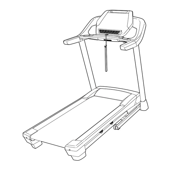
PERFORMANCE 400 C treadmill. The manual. To help us assist you, please note the product ® PERFORMANCE 400 C treadmill offers an impres- model number and serial number before contacting us. sive selection of features designed to make your The model number and the location of the serial num- workouts at home more enjoyable and effective. -
Page 6: Part Identification Chart
PART IDENTIFICATION CHART Use the drawings below to identify small parts used for assembly. The number in parentheses below each draw- ing is the key number of the part, from the PART LIST near the end of this manual. The number following the key number is the quantity used for assembly. -
Page 7: Assembly
ASSEMBLY • To watch an assembly • Left parts are marked “L” or “Left” and right parts video, go to are marked “R” or “Right.” http://productvideo.co/ assembly/proform or use • To identify small parts, see page 6. your mobile phone or smartphone to read the •... - Page 8 2. Identify the Left Upright (75). Have a second person hold the Left Upright near the Base (80). See the inset drawing. Tie the wire tie in the Wire Left Upright (75) securely around the end of the Upright Wire (70). Then, insert the Upright Wire into the lower end of the Left Upright as you pull Wire the other end of the wire tie through the Left...
- Page 9 4. Identify the Left and Right Base Covers (73, 74). Slide the Left and Right Base Covers onto the Left and Right Uprights (75, 76) as shown. 5. Set a Handrail (71) onto the Left Upright (75). Make sure that the Upright Wire (70) is not pinched.
- Page 10 6. Set the console assembly face down on a soft surface to avoid scratching the console assem- bly. Remove and discard the four indicated Screws (B). Identify the Left Tray (90) with the writing on the bottom. Attach the Left Tray with four #8 x 1/2" Screws (10).
- Page 11 8. Set the console assembly on the Handrails (71). Be careful not to pinch any wires. Insert the excess Upright Wire (70) into the Left Upright (75). Attach the console assembly with four 1/4" x 1/2" Screws (9) and four 1/4" Star Washers (11). Start all four Screws, and then tighten them.
- Page 12 10. Identify the Left and Right Handrail Inserts (35, 69). Attach the Left Handrail Insert (35) to the left Console Assembly Handrail (71) with three #8 x 3/4" Screws (6). Note: Slide the Left Handrail Insert up against the console assembly before tightening the Screws.
- Page 13 12. Raise the Frame (49) to the position shown. Have a second person hold the Frame until this step is completed. Orient the Storage Latch (51) so that the large barrel and the latch knob are oriented as shown. Attach the lower end of the Storage Latch (51) to the Base (80) with a 3/8"...
-
Page 14: Operation And Adjustment
OPERATION AND ADJUSTMENT HOW TO CONNECT THE POWER CORD nominal 120-volt circuit capable of carrying 15 or more amps. To avoid overloading the circuit, do Use a Surge Suppressor not plug other electrical devices, except for low- power devices such as cell phone chargers, into Your treadmill, like other electronic equipment, can be the surge suppressor or into an outlet on the same circuit. - Page 15 CONSOLE DIAGRAM FEATURES OF THE CONSOLE You can even listen to your favorite workout music or audio books with the console’s stereo sound system The treadmill console offers an impressive array of while you exercise. features designed to make your workouts more effec- tive and enjoyable.
-
Page 16: Turn On Power
HOW TO TURN ON THE POWER HOW TO USE THE MANUAL MODE IMPORTANT: If the treadmill has been exposed to 1. Insert the key into the console. cold temperatures, allow it to warm to room tem- perature before you turn on the power. If you do See HOW TO TURN ON THE POWER at the left. - Page 17 5. Follow your progress with the displays. 6. Measure your heart rate if desired. The matrix—When Before using you select the manual the hand- mode, the matrix will grip heart display a track that rep- rate monitor, resents 1/4 mile (400 remove the m).
- Page 18 HOW TO USE AN ONBOARD WORKOUT The workout will continue in this way until the last segment of the profile flashes in the display and the 1. Insert the key into the console. last segment ends. The walking belt will then slow to a stop.
- Page 19 HOW TO USE AN IFIT WORKOUT When you select an iFit workout, the display will show the name, duration, maximum speed setting, Note: To use an iFit workout, you must have an and distance of the workout. The display will also optional iFit module.
- Page 20 HOW TO USE THE STEREO SOUND SYSTEM Next, press the play button on your iPod, MP3 player, Increase To play music or audio books through the console’s CD player, or other personal Decrease stereo speakers, you must connect your iPod, MP3 audio player.
- Page 21 THE INFORMATION MODE CONTRAST LVL—Press the Incline increase and decrease buttons to adjust the contrast level of the The console features an information mode that keeps displays. track of treadmill information and allows you to person- If a module is connected, you may also select alize console settings.
-
Page 22: How To Fold And Move The Treadmill
HOW TO FOLD AND MOVE THE TREADMILL HOW TO FOLD THE TREADMILL HOW TO MOVE THE TREADMILL To avoid damaging the treadmill, adjust the incline Before moving the treadmill, fold it as described at the to the lowest position before you fold the treadmill. left. -
Page 23: Troubleshooting
TROUBLESHOOTING Most treadmill problems can be solved by follow- SYMPTOM: The console displays remain lit when ing the simple steps below. Find the symptom that you remove the key from the console applies, and follow the steps listed. If further assis- tance is needed, see the front cover of this manual. - Page 24 SYMPTOM: The walking belt slows when walked on Locate the Reed Switch (93) and the Magnet (44) on the left side of the Pulley (43). Turn the Pulley until the Magnet is aligned with the Reed Switch. a. Use only a surge suppressor that meets all of the Make sure that the gap between the Magnet specifications described on page 14.
- Page 25 SYMPTOM: The walking belt is off-center or slips b. If the walking belt slips when walked on, first when walked on remove the key and UNPLUG THE POWER CORD. Using the hex key, turn both idler roller a. If the walking belt is off-center, first remove the screws clockwise, 1/4 of a turn.
-
Page 26: Exercise Guidelines
EXERCISE GUIDELINES Burning Fat—To burn fat effectively, you must exer- WARNING: cise at a low intensity level for a sustained period of Before beginning this time. During the first few minutes of exercise, your or any exercise program, consult your physi- body uses carbohydrate calories for energy. -
Page 27: Part List
PART LIST Model No. PFTL59512.0 R0812B Key No. Qty. Description Key No. Qty. Description #8 x 1/2" Ground Screw Frame Spacer 3/8" x 2 1/2" Bolt Frame 3/8" Nut Right Foot Rail 3/8" x 4" Screw Storage Latch 3/8" Star Washer Right Rear Foot #8 x 3/4"... -
Page 28: Exploded Drawing
EXPLODED DRAWING A Model No. PFTL59512.0 R0812B... - Page 29 EXPLODED DRAWING B Model No. PFTL59512.0 R0812B...
- Page 30 EXPLODED DRAWING C Model No. PFTL59512.0 R0812B...
- Page 31 EXPLODED DRAWING D Model No. PFTL59512.0 R0812B...
-
Page 32: Ordering Replacement Parts
ORDERING REPLACEMENT PARTS To order replacement parts, please see the front cover of this manual. To help us assist you, be prepared to pro- vide the following information when contacting us: • the model number and serial number of the product (see the front cover of this manual) •...