Table of Contents
Advertisement
48VL---A
Performancet 14 SEER Single ---Packaged Air
Conditioner and Gas Furnace System with Puron®
(R ---410A) Refrigerant
Single and Three Phase
2---5 Nominal Tons (Sizes 24---60)
NOTE:
Read the entire instruction manual before starting the
installation.
NOTE:
Installer: Make sure the Owner's Manual and Service
Instructions are left with the unit after installation.
TABLE OF CONTENTS
SAFETY CONSIDERATIONS
. . . . . . . . . . . . . . . . . . . . . . . . . . . . . . . . . . .
. . . . . . . . . . . . . . . . . . . . . . . . . . . . . . . . . .
. . . . . . . . . . . . . . . . . . . . . . . . . . . . . . . . . . . .
. . . . . . . . . . . . . . . . . . . . . . . . . . . . . . . . .
. . . . . . . . . . . . . . . . . . . . . . . . . . . . . . .
. . . . . . . . . . . . . . . . . . . . . . . . . . . . . . . . . . . . . .
. . . . . . . . . . . . . . . . . . . . . . . . . . . . . . . . . . . . .
. . . . . . . . . . . . . . . . . . . . . . . . . . . .
. . . . . . . . . . . . . . . . . . . . . . . . . . . . . . . . .
. . . . . . . . . . . . . . . . . . . . . . . . . . . . . . . . .
. . . . . . . . . . . . . . . . . . . . . . . . . . . . . . . . . . . . . .
. . . . . . . . . . . . . . . . . . . . . . . . . . . .
. . . . . . . . . . . . . . . . . . . . . . . . . . . . . . . . . . .
. . . . . . . . . . . . . . . . . . . . . . . . . . . . . . . . . .
. . . . . . . . . . . . . . . . . . . . . . . . . . . .
Configuring Units for Downflow (Vertical)
Discharge
. . . . . . . . . . . . . . . . . . . . . . . . . . . . . . . . . . . . .
High- -Voltage Connections
. . . . . . . . . . . . . . . . . . . . . . . . . . . . .
. . . . . . . . . . . . . . . . . . . . . . . . . . .
. . . . . . . . . . . . . . . . . . . . . . . . . . . . . . . . . . .
. . . . . . . . . . . . . . . . . . . . . . . . . . . . . . . . . . . . .
Start- -Up Heating & Make Adjustments
. . . . . . . . . . . . . . . . . . . . . . . . . . .
. . . . . . . . . . . . . . . . . . . . . . . . . . . . . . . .
. . . . . . . . . . . . . . . . . . . . . . . . . . . . . . . .
. . . . . . . . . . . . . . . . . . . . . . . . . . . . .
. . . . . . . . . . . . . . . . . . . . . . . . . . . . . . .
. . . . . . . . . . . . . . . . . . . . . . . . . . . . . . . . .
. . . . . . . . . . . . . . . . . . . . . . . . . . . . . . . . .
Start- -Up Cooling & Make Adjustments
Checking & Adjusting Refrigerant Charge
. . . . . . . . . . . . . . . . . . . . . . . . . . . . . . . .
. . . . . . . . . . . . . . . . . . . . . . . . . . . . . . . . . . . . . .
Installation Instructions
. . . . . . . . . . . . . . . . . . . . . . .
. . . . . . . . . . . . . . . . .
. . . . . . . . . . . . . . . . . . . . . . . . . . .
. . . . . . . . . . . . . . . . . . . . . . . .
. . . . . . . . . . . . . . . . . . . . . . . .
. . . . . . . . . . . . . .
. . . . . . . . . . . . . . . . . . . . . . .
. . . . . . . . . . . . . . . . . . . . . . . . . .
. . . . . . . . . . . . . . . . . . . . . . . . .
. . . . . . . . . . . . . . . .
. . . . . . . . . . . . . . . . . . . . . .
. . . . . . . . . . . . . . . . . . . . .
. . . . . . . . . . . . . . . .
. . . . . . . . . . . . . . . .
. . . . . . . . . . . .
. . . . . . . . . . . . .
. . . . . . . . . . . . . . . . . . . . .
. . . . . . . . . . . . . . . . . . . . . . . . .
PAGE
1- -2
2
2- -12
2
2
2
2
2
2
3
3
Induced Draft (Combustion Air) Blower
3
3
3
9
9
9
Outdoor Coil, Indoor Coil, & Condensate Drain Pan
10
10
11
. . . . . . . . . . . . . . . . . . . . . . . . . . . . . . . . . . . . . .
11
12
12
12
12
SAFETY CONSIDERATIONS
12
Improper installation, adjustment, alteration, service maintenance,
13
or use can cause explosion, fire, electrical shock, or other
13- -24
conditions which may cause death, personal injury, or property
13
damage. Consult a qualified installer, service agency, or your
14
distributor or branch for information or assistance. The qualified
14
installer or agency must use factory- -authorized kits or accessories
14
when modifying this product. Refer to the individual instructions
15
packaged with the kits or accessories when installing.
15
22
Follow all safety codes. Wear safety glasses, protective clothing,
22
and work gloves. Have a fire extinguisher available. Read these
22
instructions thoroughly and follow all warnings or cautions
22
included in literature and attached to the unit. consult local
22
building codes, the current editions of the National Fuel Gas Code
22
(NFGC) NFPA 54/ANSI Z223.1, and the National Electrical Code
22
(NEC) NFPA 70.
22
In Canada refer to the current editions of the National Standards of
23
Canada CAN/CSA- -B149.1 and .2 Natural Gas and Propane
24
Installation codes, and Canadian Electrical Code CSA C22.1
48- -51
Recognize safety information. This is the safety- -alert symbol
48
When you see this symbol on the unit and in instructions or manu-
48
als, be alert to the potential for personal injury. Understand these
1
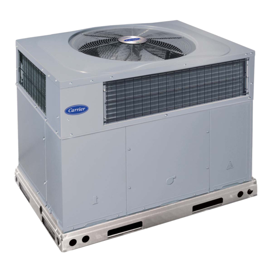
Fig. 1 - - Unit 48VL- -A
(Low NOx Model Available)
. . . . . . . . . . . . . .
. . . . . . . . . . . . . . . . . . . . . . . . . . . .
. . . . . . . . . . . . . . . . . . . . . . . . . . . . . . . . . . .
. . . . . . . . . . . . . . . . . . . . . . . . . . . . . . . . .
. . . . . . . . . . . . . . . . . . . . . . . . . . . . . . . . . . .
. . . . . . . . . . . . . . . . . . . . . . . . . . . .
. . . . . . . . . . . . . . . . . . . . . . . . . . . . . . . . . . .
. . . . . . . . . . . . . . . . . . . . .
. . . . . . . . . . . . . . . . . . . . . . . . . . . . . . .
. . . . . . . . . . . . . . . . . . . . . . . . . . . . . .
. . . . . . . . . . . . . . . . . . . . . . . . . . . . . . . . . . . .
. . . . . . . . . . . . . . . . . . . . . . . . . . . . . .
. . . . . . . . . . . . . . . . . . . . . . . . . . . .
A09033
49
49
49
49
49
49
. . . .
49
50
50
51
51
51
51
52
52
.
Advertisement
Table of Contents
Troubleshooting

Related Manuals for Carrier Performance 48VL-A


Summary of Contents for Carrier Performance 48VL-A
- Page 1 48VL---A Performancet 14 SEER Single ---Packaged Air Conditioner and Gas Furnace System with Puron® (R ---410A) Refrigerant Single and Three Phase 2---5 Nominal Tons (Sizes 24---60) Installation Instructions NOTE: Read the entire instruction manual before starting the installation. NOTE: Installer: Make sure the Owner’s Manual and Service Instructions are left with the unit after installation.
-
Page 2: Introduction
RECEIVING AND INSTALLATION signal words: DANGER, WARNING, and CAUTION. These words are used with the safety- -alert symbol. DANGER identifies Step 1 — Check Equipment the most serious hazards which will result in severe personal injury Identify Unit or death. WARNING signifies hazards which could result in per- The unit model number and serial number are stamped on the unit sonal injury or death. -
Page 3: Field Fabricate Ductwork
Training for operators of the lifting equipment should include, but not be limited to, the following: 1. Application of the lifter to the load, and adjustment of the OPTIONAL OPTIONAL RETURN SUPPLY lifts to adapt to various sizes or kinds of loads. OPENING OPENING 2. - Page 4 A09452 Fig. 3 - - 48VL- -A24- -36 Unit Dimensions...
- Page 5 A09453 Fig. 4 - - 48VL- -A42- -60 Unit Dimensions...
- Page 6 Dashed lines show cross support location for large basepan units. HVAC unit HVAC unit basepan base rails Sealing Gasket Roofcurb Anchor screw Wood nailer* Flashing field Roofcurb* supplied Insulation (field supplied) Roofing material field supplied Cant strip field supplied SMALL/COMMON CURB A09413 *Provided with roofcurb A09090...
- Page 7 CAUTION - NOTICE TO RIGGERS PRUDENCE - AVIS AUX MANIPULATEUR ACCESS PANELS MUST BE IN PLACE WHEN RIGGING. PANNEAUX D'ACCES DOIT ÊTRE EN PLACE POUR MANIPULATION. Use top skid as spreader bar. / Utiliser la palette du haut comme barre de répartition DUCTS MINIMUM HEIGHT: 36"...
- Page 8 Table 1 – Physical Data - - Unit 48VL- -A UNIT SIZE 24040 24060 30040 30060 36060 36090 42060 42090 NOMINAL CAPACITY (ton) 2 ---1/2 2 ---1/2 3 ---1/2 3 ---1/2 SHIPPING WEIGHT** lb. SHIPPING WEIGHT** (kg) Scroll COMPRESSORS Quantity REFRIGERANT (R --- 410A) Quantity lb.
-
Page 9: Connect Condensate Drain
Step 6 — Connect Condensate Drain 3. Secure flue hood to flue panel by inserting a single screw on the top flange and the bottom flange of the hood. NOTE: When installing condensate drain connection be sure to Step 8 — Install Gas Piping comply with local codes and restrictions. -
Page 10: Install Duct Connections
Table 2 – Maximum Gas Flow Capacity* LENGTH OF PIPE FT (m)† NOMINAL INTERNAL IRON PIPE DIAMETER SIZE (IN.) (IN.) (12) (15) (18) (21) (24) (27) (30) (38) (46) (53) (61) .622 — — .824 1.049 1--- 1/4 1.380 1400 1--- 1/2 1.610 2100... -
Page 11: Install Electrical Connections
Step 10 — Install Electrical Connections WARNING ELECTRICAL SHOCK HAZARD Failure to follow this warning could result in personal injury or death. The unit cabinet must have an uninterrupted, unbroken electrical ground. This ground may consist of an electrical wire connected to the unit ground screw in the control compartment, or conduit approved for electrical ground when installed in accordance with NFPA 70 (NEC) (latest edition) (in Canada, Canadian Electrical Code CSA C22.1) -
Page 12: Special Procedures For 208- -V Operation
Standard Connection 2. Connect ground lead to chassis ground connection. 3. Locate the black and yellow wires connected to the line side Run the low- -voltage leads from the thermostat, through the inlet of the contactor (if equipped). hole, and into unit low- -voltage splice box. 4. -
Page 13: Pre- -Start- -Up
PRE- -START- - UP WARNING WARNING FIRE, EXPLOSION HAZARD Failure to follow this warning could result in personal ENVIRONMENTAL, FIRE, EXPLOSION, injury, death or property damage. ELECTRICAL SHOCK HAZARD Do not purge gas supply into the combustion chamber. Do Failure to follow this warning could result in personal not use a match or other open flame to check for gas leaks. -
Page 14: Check Heating Control
Step 2 — Start- -up Heating and Make Adjust- after the thermostat has been satisfied. Please note that the integrated gas unit controller (IGC) has the capability to ments automatically reduce the evaporator “ON” delay and in- Complete the required procedures given in the Pre- -Start- -Up crease the evaporator “OFF”... -
Page 15: Adjust Gas Input
Adjust Gas Input EXAMPLE: Assume that the size of test dial is 1 cu ft, one revolution takes 32 sec, and the heating value of the gas is 1050 The gas input to the unit is determined by measuring the gas flow Btu/ft . - Page 16 A09282 Fig. 14 - - 208/230- -1- -60 Connection Wiring Diagram...
- Page 17 A09282 Fig. 14 Cont. - - 208/230- -1- -60 Ladder Wiring Diagram...
- Page 18 A09264 Fig. 15 - - 208/230- -3- -60 Connection Wiring Diagram...
- Page 19 A09264 Fig. 15 Cont. - - 208/230- -3- -60 Ladder Wiring Diagram...
- Page 20 CONNECTION WIRING DIAGRAM DANGER: ELECTRICAL SHOCK HAZARD DISCONNECT POWER BEFORE SERVICING NOTES: SCHEMATIC IF USED 1. IF ANY OF THE ORIGINAL WIRES FURNISHED ARE REPLACED, THEY MUST BE REPLACED WITH TYPE 460-3-60 90 DEG. C WIRE OR ITS EQUIVALENT. 2. SEE PRICE PAGES FOR THERMOSTAT AND SUBBASES. 3.
- Page 21 LADDER WIRING DIAGRAM DANGER: ELECTRICAL SHOCK HAZARD DISCONNECT POWER BEFORE SERVICING UNIT COMPONENT ARRANGEMENT USE COPPER CONDUCTORS ONLY OUTDOOR FAN SECTION FIELD SUPPLY 460 VAC, 60 HZ, 3PH COMPRESSOR INDOOR FAN CONTROL BOX AREA SECTION SECTION TRAN LS1 (LARGE) LS2 (SMALL) (IF USED) CONT CAP 2...
-
Page 22: Normal Operation
Normal Operation Rollout Switch An LED (light- -emitting diode) indicator is provided on the The function of the rollout switch is to close the main gas valve in integrated gas unit controller (IGC) to monitor operation. The IGC the event of flame rollout. The switch is located above the main is located by removing the control access panel (see Fig. -
Page 23: Indoor Airflow And Airflow Adjustments
320 CFM/Ton) for use with either a dehumidistat or a thermostat CAUTION that supports dehumidification. This unit is factory-set up for use with a single cooling fan speed. UNIT DAMAGE HAZARD The cooling speed is marked “LOW” on the interface fan board (IFB)(See Fig. -
Page 24: Cooling Sequence Of Operation
that static pressure is in the acceptable range for the speed tap to be used for dehumidification cooling. HEAT HIGH 6. Use any spare vinyl plugs to cap any unused speed tap wires. NOTE: For cooling operation, the recommended airflow is 350 to 450 CFM for each 12,000 Btuh of rated cooling capacity. - Page 25 Table 7 – Cooling Charging Chart A09083...
-
Page 48: Air Filter
MAINTENANCE 3. Inspect blower motor and wheel for cleanliness at the beginning of each heating and cooling season. Clean when To ensure continuing high performance and to minimize the necessary. For first heating and cooling season, inspect possibility of premature equipment failure, periodic maintenance blower wheel bi- -monthly to determine proper cleaning must be performed on this equipment. -
Page 49: Induced Draft (Combustion Air) Blower
f. Connect 5 pin plug and 4 pin plug to indoor blower 6. Remove wires connected to gas valve. Mark each wire. motor. 7. Remove the mounting screw that attaches the burner rack to g. Reinstall blower access panel (see Fig. 19). the unit base (See Fig. -
Page 50: Outdoor Fan
A07680 Fig. 21 - - Burner Rack Removed Outdoor Fan Control CAUTION Access Blower Panel Access Compressor UNIT OPERATION HAZARD Panel Access Panel Failure to follow this caution may result in damage to unit A09211 components. Fig. 19 - - Unit Access Panels Keep the condenser fan free from all obstructions to ensure proper cooling operation. -
Page 51: Refrigerant Circuit
FAN GRILLE MOTOR MOTOR SHAFT A08505 MAX DISTANCE BETWEEN TOP OF FAN GRILLE AND BOTTOM OF FAN BLADE “A” SIZE Fig. 22 - - 48VL- -A Fan Blade Position Refrigerant Circuit Puron Items Metering Device (Thermostatic Expansion Valve ) Annually inspect all refrigerant tubing connections and the unit base for oil accumulations. -
Page 52: Troubleshooting
Copeland Scroll Compressor (Puron Refrigerant) Servicing Systems on Roofs with Synthetic Materials The compressor used in this product is specifically designed to POE (polyolester) compressor lubricants are known to cause long operate with Puron (R- -410A) refrigerant and cannot be term damage to some synthetic roofing materials. - Page 53 PURONR (R- -410A) QUICK REFERENCE GUIDE S Puron refrigerant operates at 50- -70 percent higher pressures than R- -22. Be sure that servicing equipment and replacement components are designed to operate with Puron S Puron refrigerant cylinders are rose colored. S Recovery cylinder service pressure rating must be 400 psig, DOT 4BA400 or DOT BW400.
- Page 54 Table 13 – Troubleshooting Chart SYMPTOM CAUSE REMEDY Power failure Call power company Fuse blown or circuit breaker tripped Replace fuse or reset circuit breaker Defective contactor, transformer, or high--pressure, Replace component loss--of--charge or low--pressure switch Compressor and condenser fan will not start. Insufficient line voltage Determine cause and correct Incorrect or faulty wiring...
- Page 55 Table 14 – Troubleshooting Guide–Heating SYMPTOM CAUSE REMEDY Water in gas line Drain. Install drip leg. No power to furnace Check power supply fuses, wiring or circuit breaker. Check transformer. No 24--v power supply to control circuit NOTE: Some transformers have internal over--current protection that requires a cool--down period to reset.
- Page 56 START- -UP CHECKLIST (Remove and Store in Job Files) I. PRELIMINARY INFORMATION MODEL NO.: SERIAL NO.: DATE: TECHNICIAN: II. PRESTART- -UP (Insert check mark in box as each item is completed) ( ) VERIFY THAT ALL PACKING MATERIALS HAVE BEEN REMOVED FROM UNIT ( ) REMOVE ALL SHIPPING HOLD DOWN BOLTS AND BRACKETS PER INSTALLATION INSTRUCTIONS ( ) CHECK ALL ELECTRICAL CONNECTIONS AND TERMINALS FOR TIGHTNESS ( ) CHECK GAS PIPING FOR LEAKS (WHERE APPLICABLE)