Advertisement
Quick Links
_rn to the Expertg[
Owner's Information Manual
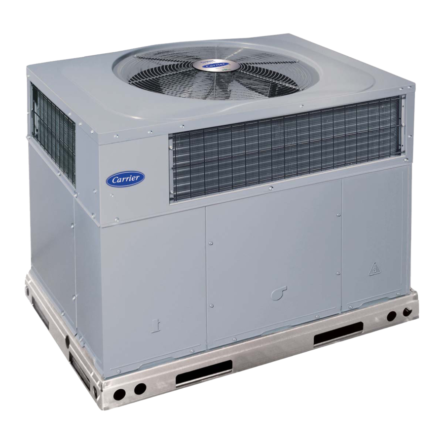
Fig. 1 - Unit 48VL
A99338
NOTE TO EQUIPMENT
OWNER:
For your convenience,
please record the model and serial numbers
of your new equipment
in the spaces
provided.
This information,
along with the installation
data and dealer contact information,
will be helpful
should
your system
require maintenance
or service.
UNIT INFORMATION
Model #
Serial #
ACCESSORIES
(List type and model #)
INSTALLATION
INFORMATION
Date Installed
DEALERSHIP
CONTACT INFORMATION
Company Name
Address
Phone Number
Technician Name
NOTE TO INSTALLER:
This manual must be left with the equipment
owner,
Advertisement

Related Manuals for Carrier 48VL


Summary of Contents for Carrier 48VL
- Page 1 _rn to the Expertg[ Owner's Information Manual A99338 Fig. 1 - Unit 48VL NOTE TO EQUIPMENT OWNER: For your convenience, please record the model and serial numbers of your new equipment in the spaces provided. This information, along with the installation data and dealer contact information, will be helpful should...
- Page 2 Note:Read the entire manual before operating unit or performing any maintenance. SAFETY CONSIDERATIONS FIRE EXPLOSION HAZARD What to do if you smell gas: Recognize safety information. This is the safety-alert symbol/_ 1. Do not try to light any appliance. When you see this symbol on the unit and in instructions or manuals 2.
-
Page 3: Front Access Pan El
To start unit gas heat: Refer to Fig. 2 for location of unit front access panel. Refer to Fig. 3 for location of gas valve. Refer to Fig. 5 while proceeding with the following steps. 1. Set the temperature selector on room thermostat to the lowest temperature setting and set system... -
Page 4: Maintenance
2.Close the external manual shutoffvalve. 3.Turn offthe electrical power supply tothe unit. 4.Remove the front access panel. FIRE, EXPLOSION, ELECTRICAL SHOCK 5.Move t he selector switch on the internal gas v alve t othe OFF HAZARD position. Failure to follow this warning could result in personal injury, 6.Replace the front a ccess... - Page 5 When installing the new filter(s), note t he direction ofthe airflow a r- rows o nthe filter f rame. If you have d ifficulty locating your a irfilter(s) orhave q uestions concerning proper filter maintenance, contact your d ealer forin- structions.
- Page 6 MAIN .,, @ STEP 1 STEP2 STEP 3 STEP 5 STEP4 STEP 6 STEP7 MAIN STEP8 STEP 9 STEP10 A07662 Fig. 5-ToStartUnitGasHeat...
- Page 7 MAIN STEP 1 STEP2 STEP 3 STEP4 STEP 5 STEP 6 A07663 Fig. 6 - To Shut Off Unit Gas Heat...
- Page 8 MAIN STEP 1 STEP2 STEP 3 STEP4 STEP 5 MAIN_ STEP6 STEP7 STEP 8 A07796 Fig. 7 - To start unit electric cooling...
-
Page 9: Burner Flame
MAIN STEP 1 STEP 2 STEP 3 A07797 electric cooling Fig. 8 - To shut off unit BURNER FLAME Warranty Certificate Your unit has a limited warranty. Be sure to read the warranty care- fully to determine the coverage for your unit. Before you call for service... - Page 10 Model No., Series Letter, & Serial No. of your equipment to ensure correct replacement part. Copyright 2007 Carrier Corporation Printed in the US.A. Edition Date: 08/07 Catalol_ No: 0M48-32 Manufacturer reserves the right to change, at any tirne_ specifications...