Advertisement
Quick Links
48VLU (K) Ultra Low NOx
Comfort 13.4 SEER2 Single-Packaged Air
Conditioner and Gas Furnace System with Puron®
(R-410A) Refrigerant
Single Phase 2-5 Nominal Tons (Sizes 24-60)
Three Phase 3-5 Nominal Tons (Sizes 36-60)
IMPORTANT: Effective January 1, 2015, all split system and packaged
air conditioners must be installed pursuant to applicable regional
efficiency standards issued by the Department of Energy.
NOTE:
Read the entire instruction manual before starting the
installation.
NOTE:
Installer: Make sure the Owner's Manual and Service
Instructions are left with the unit after installation.
Table of Contents
Safety Considerations . . . . . . . . . . . . . . . . . . . . . . . . . . . . . . . . . . . . . . . 1
Introduction. . . . . . . . . . . . . . . . . . . . . . . . . . . . . . . . . . . . . . . . . . . . . . . 2
Receiving and Installation . . . . . . . . . . . . . . . . . . . . . . . . . . . . . . . . . . . 2
Pre-start-up . . . . . . . . . . . . . . . . . . . . . . . . . . . . . . . . . . . . . . . . . . . . . . 14
Start-up . . . . . . . . . . . . . . . . . . . . . . . . . . . . . . . . . . . . . . . . . . . . . . . . . 14
Maintenance . . . . . . . . . . . . . . . . . . . . . . . . . . . . . . . . . . . . . . . . . . . . . 30
Troubleshooting . . . . . . . . . . . . . . . . . . . . . . . . . . . . . . . . . . . . . . . . . . 34
Start-up Checklist . . . . . . . . . . . . . . . . . . . . . . . . . . . . . . . . . . . . . . . . . 34
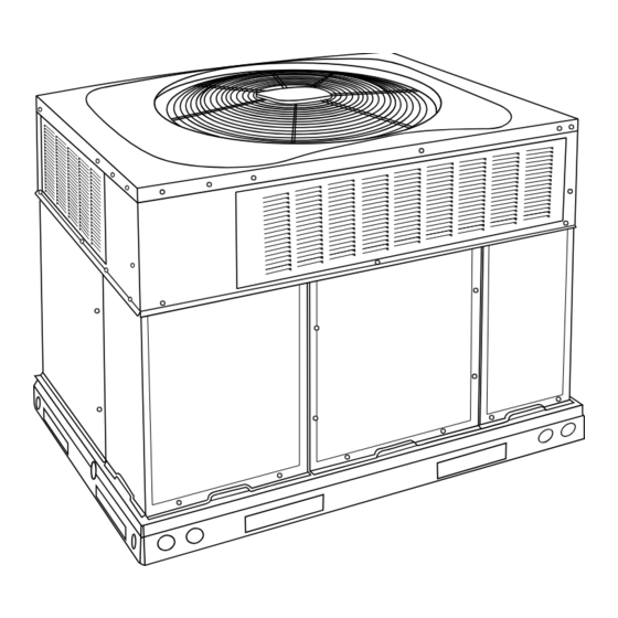
Fig. 1 - Unit 48VL
Safety Considerations
Improper installation, adjustment, alteration, service maintenance, or use
can cause explosion, fire, electrical shock, or other conditions which
may cause death, personal injury, or property damage. Consult a
qualified installer, service agency, or your distributor or branch for
information or assistance. The qualified installer or agency must use
factory-authorized kits or accessories when modifying this product.
Refer to the individual instructions packaged with the kits or accessories
when installing.
Follow all safety codes. Wear safety glasses, protective clothing, and
work gloves. Have a fire extinguisher available. Read these instructions
Installation Instructions
A09033
thoroughly and follow all warnings or cautions included in literature and
attached to the unit. consult local building codes, the current editions of
the National Fuel Gas Code (NFGC) NFPA 54/ANSI Z223.1, and the
National Electrical Code (NEC) NFPA 70.
In Canada refer to the current editions of the National Standards of
Canada CAN/CSA-B149.1 and .2 Natural Gas and Propane Installation
codes, and Canadian Electrical Code CSA C22.1
Recognize safety information. This is the safety-alert symbol
you see this symbol on the unit and in instructions or manuals, be alert to
the potential for personal injury. Understand these signal words:
DANGER, WARNING, and CAUTION. These words are used with the
safety-alert symbol. DANGER identifies the most serious hazards which
will result in severe personal injury or death. WARNING signifies
hazards which could result in personal injury or death. CAUTION is
used to identify unsafe practices which may result in minor personal
injury or product and property damage. NOTE is used to highlight
suggestions which will result in enhanced installation, reliability, or
operation.
WARNING
!
CARBON MONOXIDE POISONING HAZARD
Failure to follow this warning could result in personal injury and/or
death.
Carbon Monoxide (CO) is a colorless, odorless, and tasteless poisonous
gas that can be fatal when inhaled. Follow all installation, maintenance,
and service instructions. See additional information below regarding
the installation of a CO Alarm.
Most states in the USA and jurisdictions in Canada have laws that
require the use of Carbon Monoxide (CO) alarms with fuel burning
products. Examples of fuel burning products are furnaces, boilers, space
heaters, generators, water heaters, stoves/ranges, clothes dryers,
fireplaces, incinerators, automobiles, and other internal combustion
engines. Even if there are no laws in your jurisdiction requiring a CO
Alarm, it's highly recommended that whenever any fuel burning product
is used in or around the home or business that the dwelling be equipped
with a CO Alarm(s). The Consumer Product Safety Commission
recommends the use of CO Alarm(s). The CO Alarm(s) must be
installed, operated, and maintained according to the CO Alarm
manufacturer's instructions. For more information about Carbon
Monoxide, local laws, or to purchase a CO Alarm only, please visit the
following website
https://www.kidde.com
. When
Advertisement

Related Manuals for Carrier Comfort 48VLUK Series


Summary of Contents for Carrier Comfort 48VLUK Series
-
Page 1: Table Of Contents
48VLU (K) Ultra Low NOx Comfort 13.4 SEER2 Single-Packaged Air Conditioner and Gas Furnace System with Puron® (R-410A) Refrigerant Single Phase 2-5 Nominal Tons (Sizes 24-60) Three Phase 3-5 Nominal Tons (Sizes 36-60) Installation Instructions IMPORTANT: Effective January 1, 2015, all split system and packaged thoroughly and follow all warnings or cautions included in literature and air conditioners must be installed pursuant to applicable regional attached to the unit. -
Page 2: Introduction
48VLU (K) Ultra Low NOx: Installation Instructions Receiving and Installation CAUTION Step 1 – Check Equipment Identify Unit ELECTRICAL SHOCK HAZARD The unit model number and serial number are stamped on the unit Failure to follow this warning could result in personal injury or death. information plate. - Page 3 48VLU (K) Ultra Low NOx: Installation Instructions Step 5 – Rig and Place Unit WARNING OPTIONAL OPTIONAL RETURN SUPPLY PERSONAL INJURY OR PROPERTY DAMAGE OPENING OPENING HAZARD Failure to follow this warning could result in personal injury, death or property damage. When installing the unit on a rooftop, be sure the roof will support the additional weight.
- Page 4 48VLU (K) Ultra Low NOx: Installation Instructions available, use a spreader bar of sufficient length to protect the unit from damage. 2. Attach shackles, clevis pins, and straps to the base rails of the unit. Be sure materials are rated to hold the weight of the unit (See Fig.
- Page 5 48VLU (K) Ultra Low NOx: Installation Instructions A221498 Fig. 3 – 24-36 Unit Dimensions Manufacturer reserves the right to change, at any time, specifications and designs without notice and without obligations.
- Page 6 48VLU (K) Ultra Low NOx: Installation Instructions A221499 Fig. 4 – 42-48 Unit Dimensions Manufacturer reserves the right to change, at any time, specifications and designs without notice and without obligations.
- Page 7 48VLU (K) Ultra Low NOx: Installation Instructions Dashed lines show cross support location for large basepan units. HVAC unit HVAC unit basepan base rails Sealing Gasket Roofcurb Anchor screw Wood nailer* Flashing field supplied Roofcurb* Insulation (field supplied) Roofing material field supplied Cant strip field supplied...
- Page 8 48VLU (K) Ultra Low NOx: Installation Instructions CAUTION - NOTICE TO RIGGERS PRUDENCE - AVIS AUX MANIPULATEUR ACCESS PANELS MUST BE IN PLACE WHEN RIGGING. PANNEAUX D'ACCES DOIT ÊTRE EN PLACE POUR MANIPULATION. Use top skid as spreader bar. / Utiliser la palette du haut comme barre de répartition DUCTS MINIMUM HEIGHT: 36"...
- Page 9 Table 1 – Physical Data UNIT SIZE 24040 24060 30040 30060 36060 42060 42090 48090 60090 NOMINAL CAPACITY (ton) 2-1/2 2-1/2 3-1/2 3-1/2 SHIPPING WEIGHT lb. SHIPPING WEIGHT (kg) COMPRESSOR / QUANTITY Scroll / 1 REFRIGERANT (R-410A) Quantity lb. 5.75 Quantity (kg) REFRIGERANT METERING DEVICE Orifice...
- Page 10 48VLU (K) Ultra Low NOx: Installation Instructions Table 2 – Maximum Gas Flow Capacity † Length of Pipe ft (m) Nominal Internal Iron Pipe Diameter Size (in.) (in.) (12) (15) (18) (21) (24) (27) (30) (38) (46) (53) (61) .622 —...
- Page 11 48VLU (K) Ultra Low NOx: Installation Instructions 2. Protect all segments of piping system against physical and thermal WARNING damage. Support all piping with appropriate straps, hangers, etc. Use a minimum of one hanger every 6 ft (1.8 m). For pipe sizes FIRE OR EXPLOSION HAZARD larger than 1/2 in., follow recommendations of national codes.
- Page 12 48VLU (K) Ultra Low NOx: Installation Instructions side tabs. These plastic knockouts are held in place with tabs use vapor barrier in accordance with latest issue of Sheet Metal and similar to an electrical knockout. Discard plastic knockout covers. Air Conditioning Contractors National Association (SMACNA) and Air Conditioning Contractors of America (ACCA) minimum 5.
- Page 13 48VLU (K) Ultra Low NOx: Installation Instructions Standard Connection low-voltage entry points are used (See Fig. 3 Fig. 4 for acceptable location). Run the low-voltage leads from the thermostat, through the inlet hole, NOTE: Field supplied disconnect switch box should be positioned so and into unit low-voltage splice box.
-
Page 14: Pre-Start-Up
48VLU (K) Ultra Low NOx: Installation Instructions Pre-start-up 4. Verify the following conditions: a. Make sure gas line is free of air. Before lighting the unit for the WARNING first time, perform the following with the gas valve in the OFF position: NOTE: If the gas supply pipe was not purged before connecting the ENVIRONMENTAL, FIRE, EXPLOSION, ELECTRICAL... - Page 15 48VLU (K) Ultra Low NOx: Installation Instructions Check Gas Input Follow the lighting instructions on the heating section operation label (located on the inside of the control access panel) to start the heating Check gas input and manifold pressure after unit start-up (See Table section.
- Page 16 48VLU (K) Ultra Low NOx: Installation Instructions EXAMPLE: Assume that the size of test dial is 1 cu ft, one revolution takes 32 sec, and the heating value of the gas is 1050 Btu/ft3. Proceed as follows: 1. 41 sec. to complete one revolution 2.
- Page 17 48VLU (K) Ultra Low NOx: Installation Instructions A221593 Fig. 15 – 208/230-1-60 Ultra Low NOx Connection Wiring Diagram Manufacturer reserves the right to change, at any time, specifications and designs without notice and without obligations.
- Page 18 48VLU (K) Ultra Low NOx: Installation Instructions A221594 Fig. 16 – 208/230-1-60 Ultra Low NOx Ladder Wiring Diagram Manufacturer reserves the right to change, at any time, specifications and designs without notice and without obligations.
- Page 19 48VLU (K) Ultra Low NOx: Installation Instructions A221591 Fig. 17 – 208/230-3-60 Ultra Low NOx Connection Wiring Diagram Manufacturer reserves the right to change, at any time, specifications and designs without notice and without obligations.
- Page 20 48VLU (K) Ultra Low NOx: Installation Instructions A221592 Fig. 18 – 208/230-3-60 Ultra Low NOx Ladder Wiring Diagram Manufacturer reserves the right to change, at any time, specifications and designs without notice and without obligations.
- Page 21 48VLU (K) Ultra Low NOx: Installation Instructions Normal Operation Table 6 – LED Indications An LED (light-emitting diode) indicator is provided on the integrated Status Code LED Indication gas unit controller (IGC) to monitor operation. The IGC is located by Normal Operation removing the control access panel (see Fig.
- Page 22 48VLU (K) Ultra Low NOx: Installation Instructions is more than 2°F (1.1°C) lower than required liquid line WARNING temperature. NOTE: If the problem causing the inaccurate readings is a refrigerant EXPLOSION HAZARD leak, refer to the Check for Refrigerant Leaks section. Failure to follow this warning could result in Indoor Airflow and Airflow Adjustments death, serious personal injury, and/or property...
- Page 23 48VLU (K) Ultra Low NOx: Installation Instructions Dehumidification Cooling Fan Speed Set-up: 2-Pin Terminal IMPORTANT: Dehumidification control must open control circuit on humidity rise above set point. Use of the dehumidification cooling fan speed requires use of either a 24 VAC dehumidistat or a thermostat which includes control of a 24 VAC dehumidistat connection.
- Page 24 48VLU (K) Ultra Low NOx: Installation Instructions Table 8 – Cooling Charging Chart Superheat charging table is derived from optimum performance point. (95°F [35°C] outdoor ambient and (80°F [27°C] dry bulb; 67°F [19°C] wet bulb indoor condition.) Where a dash(--) appears do not attempt to check charge or charge unit under these conditions using the superheat method.
- Page 25 Table 9 – Dry Coil Air Delivery* - Horizontal and Downflow Discharge Sizes 24-60 Heating ESP (in. W.C.) Unit Allowable Rise Motor Speed Size Functions 0.07 0.08 0.08 0.09 Low† Blue Alternate Heating Gas Heat Rise ( Gas Heat Rise ( 0.12 0.13 0.13...
- Page 26 Table 9 – Dry Coil Air Delivery* - Horizontal and Downflow Discharge Sizes 24-60 Heating ESP (in. W.C.) Unit Allowable Rise Motor Speed Size Functions 0.09 0.10 0.11 0.11 0.11 Low† Blue Alternate Heating Gas Heat Rise ( Gas Heat Rise ( 0.14 0.15 0.15...
- Page 27 Table 9 – Dry Coil Air Delivery* - Horizontal and Downflow Discharge Sizes 24-60 Heating ESP (in. W.C.) Unit Allowable Rise Motor Speed Size Functions 1096 1044 0.14 0.15 0.16 0.18 0.19 0.19 0.20 0.21 0.22 0.23 Alternate Cooling, Low† Blue Alternate Gas Heating Gas Heat Rise (...
- Page 28 Table 9 – Dry Coil Air Delivery* - Horizontal and Downflow Discharge Sizes 24-60 Heating ESP (in. W.C.) Unit Allowable Rise Motor Speed Size Functions 0.13 0.13 0.14 0.15 0.16 0.16 0.17 0.18 0.18 0.19 Low† Blue Gas Heat Rise ( Gas Heat Rise ( 1201 1153...
- Page 29 Table 9 – Dry Coil Air Delivery* - Horizontal and Downflow Discharge Sizes 24-60 Heating ESP (in. W.C.) Unit Allowable Rise Motor Speed Size Functions 0.05 0.06 0.06 0.07 0.07 0.08 0.08 0.09 Low† Blue Alternate Heating Gas Heat Rise ( Gas Heat Rise ( 1437 1395...
-
Page 30: Maintenance
48VLU (K) Ultra Low NOx: Installation Instructions Table 12 – Filter Pressure Drop Table (IN. W.C.) Cooling Standard CFM (SCFM) Filter Size in. (mm) Tons 600 700 800 900 1000 1100 1200 1300 1400 1500 1600 1700 1800 1900 2000 2100 2200 600-1400 CFM 2.0, 12x20x1+12x20x1... - Page 31 48VLU (K) Ultra Low NOx: Installation Instructions a. Ensure proper reassembly by marking wheel orientation. If lockout occurs, unit may be reset by either momentarily interrupting b. Lift wheel from housing. When handling and/or cleaning blower power supply to unit or by turning selector switch to OFF position at the wheel, be sure not to disturb balance weights (clips) on blower thermostat.
- Page 32 48VLU (K) Ultra Low NOx: Installation Instructions done by removing the screws from the front cover of the burner box and losing the screws on each side of the top cover to allow easy removal of baffle from the burner box. Once the baffle is removed the inlet side of the burner can be accessed and cleaned.
- Page 33 48VLU (K) Ultra Low NOx: Installation Instructions FAN GRILLE MOTOR MOTOR SHAFT A08505 MAX DISTANCE BETWEEN TOP OF FAN GRILLE AND BOTTOM OF FAN BLADE “A” Size Fig. 24 – Fan Blade Position Electrical Controls and Wiring Puron (R-410A) Items Inspect and check the electrical controls and wiring annually.
-
Page 34: Troubleshooting
Access My Learning Center with your HVACpartners credentials at The Copeland scroll compressor uses 3MAF POE oil. If additional oil is www.MLCtraining.com. Please contact us at mylearning@carrier.com needed, use Uniqema RL32-3MAF. If this oil is not available, use with questions. - Page 35 48VLU (K) Ultra Low NOx: Installation Instructions Table 13 – Troubleshooting Chart SYMPTOM CAUSE REMEDY Power failure Call power company Fuse blown or circuit breaker tripped Replace fuse or reset circuit breaker Defective contactor, transformer, or high-pressure, Replace component loss-of-charge or low-pressure switch Compressor and condenser fan will not start.
- Page 36 48VLU (K) Ultra Low NOx: Installation Instructions Table 14 – Troubleshooting Guide–Heating SYMPTOM CAUSE REMEDY Water in gas line Drain. Install drip leg. No power to furnace Check power supply fuses, wiring or circuit breaker. Check transformer. No 24-v power supply to control circuit NOTE: Some transformers have internal over-current protection that requires a cool-down period to reset.
- Page 37 TEMPERATURE RISE (See Literature) RANGE ________________ MEASURED TEMPERATURE RISE _________________________ * Measured at suction inlet to compressor {Measured at liquid line leaving condenser. © 2022 Carrier. All rights reserved. Edition Date: 11/22 Catalog No: 48VL-ULN-06SI Replaces: 48VL-ULN-05SI Manufacturer reserves the right to change, at any time, specifications and designs without notice and without obligations.