Carrier Comfort 48VL-C Installation Instructions Manual
Single-packaged air conditioner and gas furnace system with puron
Hide thumbs
Also See for Comfort 48VL-C:
- Owner's information manual (10 pages) ,
- Installation instructions manual (54 pages) ,
- Installation instructions manual (60 pages)
Advertisement
c
48VL-C, 48VL-E
Comfort™14 SEER Single-Packaged Air
Conditioner and Gas Furnace System with Puron®
(R-410A) Refrigerant
Single Phase 2-5 Nominal Tons (Sizes 24-60)
Three Phase 3-5 Nominal Tons (Sizes 36-60)
IMPORTANT: Effective January 1, 2015, all split system and packaged
air conditioners must be installed pursuant to applicable regional
efficiency standards issued by the Department of Energy.
NOTE:
Read the entire instruction manual before starting the
installation.
NOTE:
Installer: Make sure the Owner's Manual and Service
Instructions are left with the unit after installation.
Table of Contents
Safety Considerations . . . . . . . . . . . . . . . . . . . . . . . . . . . . . . . . . . . . . . . 1
Introduction. . . . . . . . . . . . . . . . . . . . . . . . . . . . . . . . . . . . . . . . . . . . . . . 1
Receiving and Installation . . . . . . . . . . . . . . . . . . . . . . . . . . . . . . . . . . . 2
Pre-Start-up . . . . . . . . . . . . . . . . . . . . . . . . . . . . . . . . . . . . . . . . . . . . . . 13
Start-up . . . . . . . . . . . . . . . . . . . . . . . . . . . . . . . . . . . . . . . . . . . . . . . . . 14
Maintenance . . . . . . . . . . . . . . . . . . . . . . . . . . . . . . . . . . . . . . . . . . . . . 43
Troubleshooting . . . . . . . . . . . . . . . . . . . . . . . . . . . . . . . . . . . . . . . . . . 47
Start-up Checklist . . . . . . . . . . . . . . . . . . . . . . . . . . . . . . . . . . . . . . . . . 47
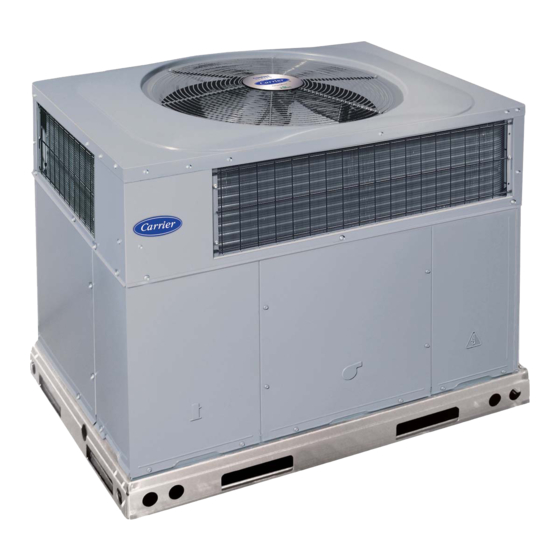
Fig. 1 - Unit 48VL
(Low NOx Model Available)
Safety Considerations
Improper installation, adjustment, alteration, service maintenance, or use
can cause explosion, fire, electrical shock, or other conditions which
may cause death, personal injury, or property damage. Consult a
qualified installer, service agency, or your distributor or branch for
information or assistance. The qualified installer or agency must use
factory-authorized kits or accessories when modifying this product.
Refer to the individual instructions packaged with the kits or accessories
when installing.
Follow all safety codes. Wear safety glasses, protective clothing, and
work gloves. Have a fire extinguisher available. Read these instructions
thoroughly and follow all warnings or cautions included in literature and
Installation Instructions
A170030
attached to the unit. consult local building codes, the current editions of
the National Fuel Gas Code (NFGC) NFPA 54/ANSI Z223.1, and the
National Electrical Code (NEC) NFPA 70.
In Canada refer to the current editions of the National Standards of
Canada CAN/CSA-B149.1 and 2 Natural Gas and Propane Installation
codes, and Canadian Electrical Code CSA C22.1
Recognize safety information. This is the safety-alert symbol
you see this symbol on the unit and in instructions or manuals, be alert to
the potential for personal injury. Understand these signal words: DAN-
GER, WARNING, and CAUTION. These words are used with the safe-
ty-alert symbol. DANGER identifies the most serious hazards which will
result in severe personal injury or death. WARNING signifies hazards
which could result in personal injury or death. CAUTION is used to iden-
tify unsafe practices which may result in minor personal injury or product
and property damage. NOTE is used to highlight suggestions which will
result in enhanced installation, reliability, or operation.
WARNING
!
ELECTRICAL SHOCK HAZARD
Failure to follow this warning could result in personal injury or death.
Before installing or servicing system, always turn off main power to
system and install lockout tag. There may be more than one disconnect
switch. Turn off accessory heater power switch if applicable.
WARNING
!
FIRE, EXPLOSION, ELECTRICAL SHOCK AND
CARBON MONOXIDE POISONING HAZARD
Failure to follow this warning could result in personal injury or unit
damage.
A qualified installer or agency must use only factory-authorized kits or
accessories when modifying this product.
Introduction
This unit (see
Fig.
1) is a fully self-contained, combination Category I
gas heating/electric cooling unit designed for outdoor installation (See
Fig.
3and
Fig. 4
for unit dimensions). All unit sizes have return and
discharge openings for both horizontal and downflow configurations,
and are factory shipped with all downflow duct openings covered. Units
may be installed either on a rooftop or on a cement slab. (See
roof curb dimensions).
In gas heating mode, this unit is designed for a minimum continuous
return-air temperature of 55°F (13°C) db and a maximum continuous
return-air temperature of 80°F (27°C) db. Failure to follow these
return-air temperature limits may affect reliability of heat exchangers,
motors, and other components.
Models with a N in the fifth position of the model number are dedicated
that are Low NOx units designed for California installations. These
. When
Fig. 5
for
Advertisement

Related Manuals for Carrier Comfort 48VL-C


Summary of Contents for Carrier Comfort 48VL-C
-
Page 1: Table Of Contents
48VL-C, 48VL-E Comfort™14 SEER Single-Packaged Air Conditioner and Gas Furnace System with Puron® (R-410A) Refrigerant Single Phase 2-5 Nominal Tons (Sizes 24-60) Three Phase 3-5 Nominal Tons (Sizes 36-60) Installation Instructions IMPORTANT: Effective January 1, 2015, all split system and packaged attached to the unit. -
Page 2: Receiving And Installation
48VL-C, 48VL-E: Installation Instructions models meet the California maximum oxides of nitrogen (NOx) CAUTION emissions requirements of 40 nanograms/joule or less as shipped from the factory and must be installed in California Air Quality Management UNITS/STRUCTURAL DAMAGE HAZARD Districts or any other regions in North America where a Low NOx rule exists. - Page 3 48VL-C, 48VL-E: Installation Instructions (such as a normal house overhang) is 48-in. (1219 mm) above the unit 2. Attach shackles, clevis pins, and straps to the base rails of the unit. top. The maximum horizontal extension of a partial overhang must not Be sure materials are rated to hold the weight of the unit (See exceed 48-in.
- Page 4 48VL-C, 48VL-E: Installation Instructions A190104 Fig. 3 – 48VL 24-36 Dimensions Manufacturer reserves the right to change, at any time, specifications and designs without notice and without obligations.
- Page 5 48VL-C, 48VL-E: Installation Instructions A190103 Fig. 4 – 48VL 42-60 Dimensions Manufacturer reserves the right to change, at any time, specifications and designs without notice and without obligations.
- Page 6 48VL-C, 48VL-E: Installation Instructions SMALL/COMMON CURB SMALL SUPPLY BASE UNIT LARGE BASE RETURN UNIT UNIT PLACEMENT ON COMMON CURB SMALL OR LARGE BASE UNIT LARGE CURB A180216 B (large B (small / common UNIT CATALOG base) base) SIZE NUMBER IN. (mm) IN.
- Page 7 48VL-C, 48VL-E: Installation Instructions CAUTION - NOTICE TO RIGGERS PRUDENCE - AVIS AUX MANIPULATEUR ACCESS PANELS MUST BE IN PLACE WHEN RIGGING. PANNEAUX D'ACCES DOIT ÊTRE EN PLACE POUR MANIPULATION. Use top skid as spreader bar. / Utiliser la palette du haut comme barre de répartition DUCTS MINIMUM HEIGHT: 36"...
- Page 8 48VL-C, 48VL-E: Installation Instructions Table 1 – Physical Data UNIT SIZE 24040 24060 30040 30060 36060 36090 42060 42090 NOMINAL CAPACITY (ton) 2-1/2 2-1/2 3-1/2 3-1/2 SHIPPING WEIGHT lb. SHIPPING WEIGHT (kg) COMPRESSOR / QUANTITY Rotary / 1 Scroll / 1 REFRIGERANT (R-410A) Quantity lb.
- Page 9 48VL-C, 48VL-E: Installation Instructions Table 1—Physical Data (Continued) UNIT SIZE 48090 48115 48130 60090 60115 60130 NOMINAL CAPACITY (ton) SHIPPING WEIGHT lb SHIPPING WEIGHT kg COMPRESSOR / QUANTITY Scroll / 1 REFRIGERANT (R-410A) Quantity lb Quantity (kg.) REFRIGERANT METERING DEVICE Orifice ORIFICE ID in./mm .080 / 2.03...
- Page 10 48VL-C, 48VL-E: Installation Instructions 4. The use of copper tubing for gas piping is NOT approved by the WARNING state of Massachusetts. In the absence of local building codes, adhere to the following pertinent CARBON MONOXIDE POISONING HAZARD recommendations: Failure to follow this warning could result in personal injury or death. 1.
- Page 11 48VL-C, 48VL-E: Installation Instructions screwdriver and hammer. Push cover down to break rear and left WARNING side tabs. These plastic knockouts are held in place with tabs similar to an electrical knockout. Discard plastic knockout covers. FIRE OR EXPLOSION HAZARD 5.
- Page 12 48VL-C, 48VL-E: Installation Instructions use vapor barrier in accordance with latest issue of Sheet Metal and low-voltage entry points are used (See Fig. 3and Fig. 4 for acceptable Air Conditioning Contractors National Association (SMACNA) location). and Air Conditioning Contractors of America (ACCA) minimum NOTE: Field supplied disconnect switch box should be positioned so installation standards for heating and air conditioning systems.
-
Page 13: Pre-Start-Up
48VL-C, 48VL-E: Installation Instructions Pre-Start-up Locate six (seven for 3-phase) 18-gage wires leaving control box. These low-voltage connection leads can be identified by the colors red, green, WARNING yellow, brown, blue, and white (See Fig. 10). A gray wire is standard on 3-phase units for connection to an economizer. -
Page 14: Start-Up
48VL-C, 48VL-E: Installation Instructions 4. Verify the following conditions: a. Make sure gas line is free of air. Before lighting the unit for the first time, perform the following with the gas valve in the OFF position: NOTE: If the gas supply pipe was not purged before connecting the unit, it will be full of air. - Page 15 48VL-C, 48VL-E: Installation Instructions Adjust Gas Input • The rated gas inputs shown in Table 6 are for altitudes from sea level to 2000 ft (610 m) above sea level. These inputs are based on natural The gas input to the unit is determined by measuring the gas flow at the gas with a heating value of 1025 Btu/ft at 0.60 specific gravity, or meter or by measuring the manifold pressure.
- Page 16 48VL-C, 48VL-E: Installation Instructions 2. Turn plastic adjustment screw clockwise to increase gas input, or 4. Turn off gas supply to unit. Remove manometer from pressure tap turn plastic adjustment screw counterclockwise to decrease input and replace pipe plug on gas valve. (See Fig.
- Page 17 48VL-C, 48VL-E: Installation Instructions A150502 Fig. 14 – 208/230-1-60 Connection Wiring Diagram Manufacturer reserves the right to change, at any time, specifications and designs without notice and without obligations.
- Page 18 48VL-C, 48VL-E: Installation Instructions A150510 Fig. 15 – 208/230-1-60 Ladder Wiring Diagram Manufacturer reserves the right to change, at any time, specifications and designs without notice and without obligations.
- Page 19 48VL-C, 48VL-E: Installation Instructions A150508 Fig. 16 – 208/230-3-60 Connection Wiring Diagram Manufacturer reserves the right to change, at any time, specifications and designs without notice and without obligations.
- Page 20 48VL-C, 48VL-E: Installation Instructions A150511 Fig. 17 – 208/230-3-60 Ladder Wiring Diagram Manufacturer reserves the right to change, at any time, specifications and designs without notice and without obligations.
- Page 21 48VL-C, 48VL-E: Installation Instructions A150509 Fig. 18 – 460-3-60 Connection Wiring Diagram Manufacturer reserves the right to change, at any time, specifications and designs without notice and without obligations.
- Page 22 48VL-C, 48VL-E: Installation Instructions A150512 Fig. 19 – 460-3-60 Ladder Wiring Diagram Manufacturer reserves the right to change, at any time, specifications and designs without notice and without obligations.
- Page 23 48VL-C, 48VL-E: Installation Instructions Normal Operation Table 7 – LED Indications An LED (light-emitting diode) indicator is provided on the integrated STATUS CODE LED INDICATION gas unit controller (IGC) to monitor operation. The IGC is located by Normal Operation removing the control access panel (see Fig.
- Page 24 48VL-C, 48VL-E: Installation Instructions Checking and Adjusting Refrigerant Charge determine desired system operating liquid line temperature (See Table The refrigerant system is fully charged with Puron (R-410A) refrigerant 6. Compare actual liquid line temperature with desired liquid line and is tested and factory sealed. Allow system to operate a minimum of temperature.
- Page 25 48VL-C, 48VL-E: Installation Instructions Gas Heating Fan Speed Set-up (3 Phase Models) must open the control circuit on humidity rise above the dehumidification set point. To change the gas heating speed: 1. Remove fan speed tap wire from the “LOW” terminal on the 1.
- Page 26 48VL-C, 48VL-E: Installation Instructions thermostat breaks the circuit between thermostat terminal R to terminals Y and G. These open circuits deenergize contactor coil C. The condenser HEAT HIGH and compressor motors stop. After a 60-sec. delay, the blower motor stops. The unit is in a standby condition, waiting for the next call for cooling from the room thermostat.
- Page 27 48VL-C, 48VL-E: Installation Instructions Table 9 – Cooling Charging Chart Superheat charging table is derived from optimum performance point. (95°F [35°C] outdoor ambient and (80°F [27°C] dry bulb; 67°F [19°C] wet bulb indoor condition.) Where a dash (-) appears do not attempt to check charge or charge unit under these conditions using the superheat method. (Weigh in method should be used.) A150625 To properly check or adjust charge, conditions must be favorable for subcooling charging.
- Page 28 Table 10 – Dry Coil Air Delivery - Horizontal and Downflow Discharge Sizes 24-60 208/230VAC - 1 Phase ESP (in. W.C.) Heating Rise Allowable Unit Size Motor Speed °F (°C) Functions 0.09 0.10 0.10 0.11 † Blue Alternate Heating Gas Heat Rise (°F) Gas Heat Rise (°C) Heating 0.14...
- Page 29 Table 10 – Dry Coil Air Delivery - Horizontal and Downflow Discharge Sizes 24-60 208/230VAC - 1 Phase (Continued) Heating Rise Allowable ESP (in. W.C.) Unit Size Motor Speed °F (°C) Functions 0.09 0.10 0.10 0.11 † Blue Gas Heat Rise (°F) Gas Heat Rise (°C) 0.14 0.15...
- Page 30 Table 10 – Dry Coil Air Delivery - Horizontal and Downflow Discharge Sizes 24-60 208/230VAC - 1 Phase (Continued) Heating Rise Allowable ESP (in. W.C.) Unit Size Motor Speed °F (°C) Functions 1001 0.13 0.13 0.14 0.14 0.15 0.16 0.17 0.18 0.19 0.20...
- Page 31 Table 10 – Dry Coil Air Delivery - Horizontal and Downflow Discharge Sizes 24-60 208/230VAC - 1 Phase (Continued) Heating Rise Allowable ESP (in. W.C.) Unit Size Motor Speed °F (°C) Functions 0.06 0.07 0.07 0.08 0.08 0.09 † Blue Gas Heat Rise (°F) Gas Heat Rise (°C) 1430...
- Page 32 Table 10 – Dry Coil Air Delivery - Horizontal and Downflow Discharge Sizes 24-60 208/230VAC - 1 Phase (Continued) Heating Rise Allowable ESP (in. W.C.) Unit Size Motor Speed °F (°C) Functions 0.09 0.10 0.10 0.11 0.12 0.12 0.13 0.14 0.14 †...
- Page 33 Table 11 – Dry Coil Air Delivery - Horizontal Discharge Sizes 36-60 3 Phase Models Only External Static Pressure (IN. W.C.) Heating Motor Wire Unit Rise Range Speed Color Blue Heating Rise ( Heating Rise ( 1136 1080 1015 † Pink Heating Rise ( Med-Low...
- Page 34 Table 11 – Dry Coil Air Delivery - Horizontal Discharge Sizes 36-60 3 Phase Models Only (Continued) Heating Motor Wire External Static Pressure (IN. W.C.) Unit Rise Range Speed Color Blue Heating Rise ( Heating Rise ( 1002 Med-Low Pink Heating Rise ( Heating Rise ( 1255...
- Page 35 Table 11 – Dry Coil Air Delivery - Horizontal Discharge Sizes 36-60 3 Phase Models Only (Continued) Heating Motor Wire External Static Pressure (IN. W.C.) Unit Rise Range Speed Color 1402 1351 1311 1263 1224 1172 1136 1080 1041 Blue Heating Rise ( Heating Rise ( 1233...
- Page 36 Table 11 – Dry Coil Air Delivery - Horizontal Discharge Sizes 36-60 3 Phase Models Only (Continued) Heating Motor Wire External Static Pressure (IN. W.C.) Unit Rise Range Speed Color 1445 1389 1341 1281 1236 1189 1139 1072 1027 Blue Heating Rise ( Heating Rise ( 1558...
- Page 37 Table 12 – Dry Coil Air Delivery - Downflow Discharge Sizes 36-60 3 Phase Models Only External Static Pressure (IN. W.C.) Heating Motor Wire Unit Rise Range Speed Color WATTS Blue 0.22 0.23 0.23 0.24 0.25 0.25 0.26 0.27 0.28 0.27 Heating Rise ( Heating Rise (...
- Page 38 Table 12 – Dry Coil Air Delivery - Downflow Discharge Sizes 36-60 3 Phase Models Only (Continued) Heating Motor Wire External Static Pressure (IN. W.C.) Unit Rise Range Speed Color WATTS Blue 0.13 0.14 0.15 0.16 0.17 0.18 0.18 0.20 0.20 0.21 Heating Rise (...
- Page 39 Table 12 – Dry Coil Air Delivery - Downflow Discharge Sizes 36-60 3 Phase Models Only (Continued) Heating Motor Wire External Static Pressure (IN. W.C.) Unit Rise Range Speed Color 1503 1457 1423 1374 1330 1287 1241 1199 1153 1111 WATTS †...
- Page 40 Table 12 – Dry Coil Air Delivery - Downflow Discharge Sizes 36-60 3 Phase Models Only (Continued) Heating Motor Wire External Static Pressure (IN. W.C.) Unit Rise Range Speed Color 1503 1457 1423 1374 1330 1287 1241 1199 1153 1111 WATTS Blue 0.24...
- Page 41 Table 12 – Dry Coil Air Delivery - Downflow Discharge Sizes 36-60 3 Phase Models Only (Continued) Heating Motor Wire External Static Pressure (IN. W.C.) Unit Rise Range Speed Color 1479 1436 1387 1346 1298 1253 1206 1160 1114 1061 WATTS Blue 0.24...
- Page 42 Table 13 – Wet Coil Pressure Drop (IN. W.C.) Standard CFM (SCFM) Unit Size 1000 1100 1200 1300 1400 1500 1600 1700 1800 1900 2000 2100 2200 0.03 0.04 0.04 0.05 0.06 0.05 0.06 0.07 0.08 0.11 0.06 0.06 0.09 0.10 0.11 0.14...
-
Page 43: Maintenance
48VL-C, 48VL-E: Installation Instructions Maintenance 6. Check and inspect heating section before each heating season. Clean and adjust when necessary. To ensure continuing high performance and to minimize the possibility 7. Check flue hood and remove any obstructions, if necessary. of premature equipment failure, periodic maintenance must be Air Filter performed on this equipment. - Page 44 48VL-C, 48VL-E: Installation Instructions season. For the first heating season, inspect blower wheel bimonthly to WARNING determine proper cleaning frequency. To inspect blower wheel, remove draft hood assembly. Shine a flashlight FIRE, EXPLOSION HAZARD into opening to inspect wheel. If cleaning is required, remove induced-draft blower assembly as follows: Failure to follow this warning could result in personal injury, death or property damage.
- Page 45 48VL-C, 48VL-E: Installation Instructions Outdoor Fan WARNING UNIT OPERATION HAZARD Failure to follow this caution may result in damage to unit components. Keep the condenser fan free from all obstructions to ensure proper cooling operation. Never place articles on top of the unit. 1.
- Page 46 48VL-C, 48VL-E: Installation Instructions FAN GRILLE MOTOR MOTOR SHAFT A08505 Max Distance Between Top of Fan Grille and Bottom of Fan Blade “A” Size 1804 Fig. 26 – Fan Blade Position Refrigerant Circuit pressure switches must not be used as replacements for the Puron (R-410A) system.
-
Page 47: Troubleshooting
48VL-C, 48VL-E: Installation Instructions Synthetic Roof Precautionary Procedure WARNING 1. Cover extended roof working area with an impermeable polyethylene (plastic) drip cloth or tarp. Cover an approximate 10 FIRE/EXPLOSION HAZARD X 10 ft. (3.1 m X 3.1 m) area. Failure to follow this warning could result in personal injury or death 2. - Page 48 48VL-C, 48VL-E: Installation Instructions Table 16 – Troubleshooting Chart SYMPTOM CAUSE REMEDY Power failure Call power company Fuse blown or circuit breaker tripped Replace fuse or reset circuit breaker Defective contactor, transformer, or high-pressure, Replace component loss-of-charge or low-pressure switch Compressor and condenser fan will not start.
- Page 49 48VL-C, 48VL-E: Installation Instructions Table 17 – Troubleshooting Guide–Heating SYMPTOM CAUSE REMEDY Water in gas line Drain. Install drip leg. No power to furnace Check power supply fuses, wiring or circuit breaker. Check transformer. No 24-v power supply to control circuit NOTE: Some transformers have internal over-current protection that requires a cool-down period to reset.
- Page 50 48VL-C, 48VL-E: Installation Instructions Table 18 – Troubleshooting Guide–LED Status Codes SYMPTOM CAUSE REMEDY Check 5-amp fuse son IGC*, power to unit, 24-v circuit breaker, No Power or Hardware failure and transformer. Units without a 24-v circuit breaker have an Loss of power to control module (IGC)*.
- Page 51 48VL-C, 48VL-E: Installation Instructions Start-Up Checklist (Remove and Store in Job Files) I. PRELIMINARY INFORMATION MODEL NO.: ____________________________________________ SERIAL NO.: ____________________________________________ DATE: __________________________________________________ TECHNICIAN: ___________________________________________ II. PRESTART-UP (Insert check mark in box as each item is completed) (¦ ) VERIFY THAT ALL PACKING MATERIALS HAVE BEEN REMOVED FROM UNIT ( ) REMOVE ALL SHIPPING HOLD DOWN BOLTS AND BRACKETS PER INSTALLATION INSTRUCTIONS ( ) CHECK ALL ELECTRICAL CONNECTIONS AND TERMINALS FOR TIGHTNESS ( ) CHECK GAS PIPING FOR LEAKS (WHERE APPLICABLE)
- Page 52 48VL-C, 48VL-E: Installation Instructions ©2019 Carrier Corp. 7310 W. Morris Street • Indianapolis, IN 46231 Catalog No: 48VL-16SI Edition Date: 11/19 Replaces: 48VL-15SI Manufacturer reserves the right to change, at any time, specifications and designs without notice and without obligations.