Table of Contents
Advertisement
Quick Links
48VL---C, 48VL---D
Comfortt 14 SEER Single ---Packaged Air
Conditioner and Gas Furnace System with Puron
(R ---410A) Refrigerant
Single Phase 2---5 Nominal Tons (Sizes 24---60)
Three Phase 3---5 Nominal Tons (Sizes 36---60)
IMPORTANT: Effective January 1, 2015, all split system and
packaged air conditioners must be installed pursuant to applicable
regional efficiency standards issued by the Department of Energy.
NOTE:
Read the entire instruction manual before starting the
installation.
NOTE:
Installer: Make sure the Owner's Manual and Service
Instructions are left with the unit after installation.
TABLE OF CONTENTS
. . . . . . . . . . . . . . . . . . . . . . . . . . . . . . . . . . .
. . . . . . . . . . . . . . . . . . . . . . . . . . . . . . . . . .
. . . . . . . . . . . . . . . . . . . . . . . . . . . . . . . . . . . .
. . . . . . . . . . . . . . . . . . . . . . . . . . . . . . . . .
. . . . . . . . . . . . . . . . . . . . . . . . . . . . . . .
. . . . . . . . . . . . . . . . . . . . . . . . . . . . . . . . . . . . . .
. . . . . . . . . . . . . . . . . . . . . . . . . . . . . . . . . . . . .
. . . . . . . . . . . . . . . . . . . . . . . . . . . .
. . . . . . . . . . . . . . . . . . . . . . . . . . . . . . . . .
. . . . . . . . . . . . . . . . . . . . . . . . . . . . . . . . .
. . . . . . . . . . . . . . . . . . . . . . . . . . . . . . . . . . . . . .
. . . . . . . . . . . . . . . . . . . . . . . . . . . .
. . . . . . . . . . . . . . . . . . . . . . . . . . . . . . . . . . .
. . . . . . . . . . . . . . . . . . . . . . . . . . . . . . . . . .
. . . . . . . . . . . . . . . . . . . . . . . . . . . .
. . . . . . . . . . . . . . . . . . . . . . . . . . . . . . . . . . . . .
. . . . . . . . . . . . . . . . . . . . . . . . . . . . .
. . . . . . . . . . . . . . . . . . . . . . . . . . .
. . . . . . . . . . . . . . . . . . . . . . . . . . . . . . . . . . .
. . . . . . . . . . . . . . . . . . . . . . . . . . . . . . . . . . . . .
. . . . . . . . . . . . . . . . . . . . . . . . . . .
. . . . . . . . . . . . . . . . . . . . . . . . . . . . . . . .
. . . . . . . . . . . . . . . . . . . . . . . . . . . . . . . .
. . . . . . . . . . . . . . . . . . . . . . . . . . . . .
. . . . . . . . . . . . . . . . . . . . . . . . . . . . . . .
. . . . . . . . . . . . . . . . . . . . . . . . . . . . . . . . .
. . . . . . . . . . . . . . . . . . . . . . . . . . . . . . . . .
Installation Instructions
. . . . . . . . . . . . . . . . . . . . . . . . .
. . . . . . . . . . . . . . . . .
. . . . . . . . . . . . . . . . . . . . . . . . . . .
. . . . . . . . . . . . . . . . . . . . . . . .
. . . . . . . . . . . . . . . . . . . . . . . .
. . . . . . . . . . . . . .
. . . . . . . . . . . . . . . . . . . . . . .
. . . . . . . . . . . . . . . . . . . . . . . . . .
. . . . . . . . . . . . . . . . . . . . . . . . .
. . . . . . . . . . . . . . . .
. . . . . . . . . . . . . . . . . . . . . .
. . . . . . . . . . . . . . . . . . . . .
. . . . . . . . . . . . . . . .
. . . . . . . . . . . . . . . .
. . . . . . . . . . . .
. . . . . . . . . . . . .
. . . . . . . . . . . . . . . . . . . . .
PAGE
1
2
2- -12
2
2
2
2
2
2
3
3
3
3
3
8
. . . . . . . . . . . . . . . . . . . . . . . . . . . . . . . . . . . . . .
8
9
10
10
11
11
11
12
12
12
12
. . . . . . . . . . . . . . . . . . . . . . . . . . . . . . . . . . . . . .
12
13- -24
13
13
13
SAFETY CONSIDERATIONS
14
14
Improper installation, adjustment, alteration, service maintenance,
15
or use can cause explosion, fire, electrical shock, or other
22
conditions which may cause death, personal injury, or property
22
damage. Consult a qualified installer, service agency, or your
22
distributor or branch for information or assistance. The qualified
22
installer or agency must use factory- -authorized kits or accessories
22
when modifying this product. Refer to the individual instructions
22
packaged with the kits or accessories when installing.
22
Follow all safety codes. Wear safety glasses, protective clothing,
23
and work gloves. Have a fire extinguisher available. Read these
23
instructions thoroughly and follow all warnings or cautions
24
1
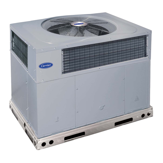
Fig. 1 - - Unit 48VL- -C, 48VL- -D
(Low NOx Model Available)
. . . . . . . . . . . . . . . . . . . . . . . . . . . . . . . .
. . . . . . . . . . . . . . . . . . . . . . . . .
. . . . . . . . . . . . . .
. . . . . . . . . . . . . . . . . . . . . . . . . . . .
. . . . . . . . . . . . . . . . . . . . . . . . . . . . . . . . . . .
. . . . . . . . . . . . . . . . . . . . . . . . . . . . . . . . .
. . . . . . . . . . . . . . . . . . . . . . . . . . . . . . . . . . .
. . . . . . . . . . . . . . . . . . . . . . . . . . . .
. . . . . . . . . . . . . . . . . . . . . . . . . . . . . . . . . . .
. . . . . . . . . . . . . . . . . . . . .
. . . . . . . . . . . . . . . . . . . . . . . . . . . . . . .
. . . . . . . . . . . . . . . . . . . . . . . . . . . . . .
. . . . . . . . . . . . . . . . . . . . . . . . . . . . . . . . . . . .
. . . . . . . . . . . . . . . . . . . . . . . . . . . . . .
. . . . . . . . . . . . . . . . . . . . . . . . . . . .
A170030
51- -54
51
51
52
52
52
52
52
52
. . . .
52
53
53
54
54
54
54
55
55
Advertisement
Table of Contents

Related Manuals for Carrier 48VL-D


Summary of Contents for Carrier 48VL-D
-
Page 1: Table Of Contents
48VL---C, 48VL---D Comfortt 14 SEER Single ---Packaged Air Conditioner and Gas Furnace System with Puron (R ---410A) Refrigerant Single Phase 2---5 Nominal Tons (Sizes 24---60) Three Phase 3---5 Nominal Tons (Sizes 36---60) Installation Instructions IMPORTANT: Effective January 1, 2015, all split system and packaged air conditioners must be installed pursuant to applicable regional efficiency standards issued by the Department of Energy. -
Page 2: Introduction
RECEIVING AND INSTALLATION included in literature and attached to the unit. consult local building codes, the current editions of the National Fuel Gas Code Step 1 — Check Equipment (NFGC) NFPA 54/ANSI Z223.1, and the National Electrical Code Identify Unit (NEC) NFPA 70. -
Page 3: Field Fabricate Ductwork
Training for operators of the lifting equipment should include, but not be limited to, the following: 1. Application of the lifter to the load, and adjustment of the OPTIONAL OPTIONAL RETURN SUPPLY lifts to adapt to various sizes or kinds of loads. OPENING OPENING 2. - Page 4 A180293 Fig. 3 - - 24- -36 Unit Dimensions...
- Page 5 Fig. 4 - - 42- -60 Unit Dimensions...
- Page 6 SMALL/COMMON CURB SMALL SUPPLY BASE UNIT LARGE BASE RETURN UNIT UNIT PLACEMENT ON COMMON CURB SMALL OR LARGE BASE UNIT LARGE CURB A180216 B (small / common B (large UNIT CATALOG base) base) SIZE NUMBER IN. (mm) IN. (mm) (mm) IN.
- Page 7 CAUTION - NOTICE TO RIGGERS PRUDENCE - AVIS AUX MANIPULATEUR ACCESS PANELS MUST BE IN PLACE WHEN RIGGING. PANNEAUX D'ACCES DOIT ÊTRE EN PLACE POUR MANIPULATION. Use top skid as spreader bar. / Utiliser la palette du haut comme barre de répartition DUCTS MINIMUM HEIGHT: 36"...
-
Page 8: Connect Condensate Drain
Table 1—Physical Data Con’t UNIT SIZE 48090 48115 48130 60090 60115 60130 NOMINAL CAPACITY (ton) SHIPPING WEIGHT lb SHIPPING WEIGHT kg COMPRESSOR / QUANTITY Scroll / 1 REFRIGERANT (R --- 410A) Quantity lb Quantity (kg.) REFRIGERANT METERING DEVICE Orifice ORIFICE ID in./mm .080 / 2.03 .084 / 2.14 OUTDOOR COIL... -
Page 9: Install Gas Piping
3. Apply joint compound (pipe dope) sparingly and only to WARNING male threads of joint when making pipe connections. Use only pipe dope that is resistant to action of liquefied petroleum gases as specified by local and/or national codes. CARBON MONOXIDE POISONING HAZARD Never use Teflon tape. -
Page 10: Install Duct Connections
8. Check leaks field- -installed factory- -installed gas lines after all piping connections have been completed. Use a commercially available soap solution (or method specified by local codes and/or regulations). Step 9 — Install Duct Connections The unit has duct flanges on the supply- - and return- -air openings on the side and bottom of the unit. -
Page 11: Install Electrical Connections
Table 2 – Maximum Gas Flow Capacity* LENGTH OF PIPE FT (m)† NOMINAL INTERNAL IRON PIPE DIAMETER SIZE (IN.) (IN.) (12) (15) (18) (21) (24) (27) (30) (38) (46) (53) (61) .622 — — .824 1.049 1--- 1/4 1.380 1400 1--- 1/2 1.610 2100... -
Page 12: Control Voltage Connections
to the occupants of the conditioned space, and inefficient energy WARNING utilization; however, the required setting may be changed slightly to provide a greater degree of comfort for a particular installation. ELECTRICAL SHOCK FIRE/EXPLOSION HAZARD Transformer Protection Failure to follow this warning could result in personal The transformer is of the energy- -limiting type, however a direct injury or death and property damage. -
Page 13: Check For Refrigerant Leaks
Step 2 — Start- -up Heating and Make Adjust- WARNING ments Complete the required procedures given in the Pre- -Start- -Up FIRE, EXPLOSION HAZARD section before starting the unit. Do not jumper any safety devices Failure to follow this warning could result in personal when operating the unit. -
Page 14: Check Gas Input
5. For 3- -phase models the evaporator fan will turn on 45 sec. CAUTION after the flame has been established. The evaporator fan will turn off 45 sec. after the thermostat has been satisfied. For single phase models the evaporator fan will turn on 30 sec. UNIT DAMAGE HAZARD after the flame has been established. -
Page 15: Check Burner Flame
Table 4 – High Altitude Compensation, Natural Gas - - Single Phase Models Rated Heating Input (Btu/hr), Natural Gas at Installation Altitude Above Sea Level, U.S.A.* Nameplate 0 to 2000 ft 2001 to 3000 ft* 3001 to 4000 ft 4001 to 5000 ft 5001 to 6000 ft Input (Btu/hr) (0--- 610 m) - Page 16 A150502 Fig. 14 - - 208/230- -1- -60 Connection Wiring Diagram...
- Page 17 A150510 Fig. 14 Cont. - - 208/230- -1- -60 Ladder Wiring Diagram...
- Page 18 A150508 Fig. 15 - - 208/230- -3- -60 Connection Wiring Diagram...
- Page 19 A150511 Fig. 15 Cont. - - 208/230- -3- -60 Ladder Wiring Diagram...
- Page 20 A150509 Fig. 16 - - 460- -3- -60 Connection Wiring Diagram...
- Page 21 A150512 Fig. 16 Cont. - - 460- -3- -60 Ladder Wiring Diagram...
-
Page 22: Normal Operation
Normal Operation Table 7 – LED Indications STATUS CODE LED INDICATION An LED (light- -emitting diode) indicator is provided on the Normal Operation integrated gas unit controller (IGC) to monitor operation. The IGC No Power or Hardware Failure is located by removing the control access panel (see Fig. 20). Check fuse, low voltage circuit 1 Flash During normal operation, the LED is continuously on (See Table 7... -
Page 23: Checking & Adjusting Refrigerant Charge
Checking and Adjusting Refrigerant Charge (psig) to determine desired system operating liquid line temperature (See Table 9). The refrigerant system is fully charged with PuronR (R- -410A) 6. Compare actual liquid line temperature with desired liquid refrigerant and is tested and factory sealed. Allow system to operate line temperature. -
Page 24: Cooling Sequence Of Operation
the temperature rise associated with each fan speed for a speed in Table 11 or 12 that will deliver the nominal cooling given static pressure. Make sure that the speed chosen airflow as listed in Table 1 for each size. delivers a temperature rise within the rise range listed on the 3. - Page 25 HEAT HIGH OILL AB A15 R3 R5 R6 C 24VAC SSTZ-8 W2 Y2/ DH G A09058 Fig. 18 - - Interface Fan Board (IFB) Shunt in no Shunt in dehumidification dehumidification position position A14399 Fig. 17 - - Single Phase IGC Board...
- Page 26 Table 9 – Cooling Charging Chart Superheat charging table is derived from optimum performance point. (95_F [35_C] outdoor ambient and (80_F [27_C] dry bulb; 67_F [19_C] wet bulb indoor condition.) Where a dash( --- ---) appears do not attempt to check charge or charge unit under these conditions using the superheat method. (Weigh in method should be used.) A150625 To properly check or adjust charge, conditions must be favorable for subcooling charging.
-
Page 51: Maintenance
MAINTENANCE 3. Inspect blower motor and wheel for cleanliness at the beginning of each heating and cooling season. Clean when To ensure continuing high performance and to minimize the necessary. For first heating and cooling season, inspect possibility of premature equipment failure, periodic maintenance blower wheel bi- -monthly to determine proper cleaning must be performed on this equipment. -
Page 52: Induced Draft (Combustion Air) Blower
f. Connect 5 pin plug and 4 pin plug to indoor blower 8. Partially slide the burner rack out of the unit (see Fig. 19 motor. and 22). Remove ignitor and sensor wires at the burner as- g. Reinstall blower access panel (see Fig. 20). sembly. -
Page 53: Outdoor Fan
A07680 Fig. 22 - - Burner Rack Removed Outdoor Fan CONTROL CAUTION ACCESS PANEL BLOWER ACCESS PANEL COMPRESSOR UNIT OPERATION HAZARD ACCESS PANEL A170032 Failure to follow this caution may result in damage to unit Fig. 20 - - Unit Access Panels components. -
Page 54: Refrigerant Circuit
FAN GRILLE MOTOR MOTOR SHAFT A08505 MAX DISTANCE BETWEEN TOP OF FAN GRILLE AND BOTTOM OF FAN BLADE “A” SIZE Fig. 23 - - Fan Blade Position Refrigerant Circuit Pressure Switches Annually inspect all refrigerant tubing connections. Pressure switches are protective devices wired into control circuit (low voltage). -
Page 55: Troubleshooting
Servicing Systems on Roofs with Synthetic Materials The compressor is an electrical (as well as mechanical) device. Exercise extreme caution when working near compressors. Power POE (polyolester) compressor lubricants are known to cause long should be shut off, if possible, for most troubleshooting techniques. term damage to some synthetic roofing materials. - Page 56 PURONR (R- -410A) QUICK REFERENCE GUIDE S Puron refrigerant operates at 50- -70 percent higher pressures than R- -22. Be sure that servicing equipment and replacement components are designed to operate with Puron S Puron refrigerant cylinders are rose colored. S Recovery cylinder service pressure rating must be 400 psig, DOT 4BA400 or DOT BW400.
- Page 57 Table 16 – Troubleshooting Chart SYMPTOM CAUSE REMEDY Power failure Call power company Fuse blown or circuit breaker tripped Replace fuse or reset circuit breaker Defective contactor, transformer, or high--pressure, Replace component loss--of--charge or low--pressure switch Compressor and condenser fan will not start. Insufficient line voltage Determine cause and correct Incorrect or faulty wiring...
- Page 58 Table 17 – Troubleshooting Guide–Heating SYMPTOM CAUSE REMEDY Water in gas line Drain. Install drip leg. No power to furnace Check power supply fuses, wiring or circuit breaker. Check transformer. No 24--v power supply to control circuit NOTE: Some transformers have internal over--current protection that requires a cool--down period to reset.
- Page 59 START- -UP CHECKLIST (Remove and Store in Job Files) I. PRELIMINARY INFORMATION MODEL NO.: SERIAL NO.: DATE: TECHNICIAN: II. PRESTART- -UP (Insert check mark in box as each item is completed) ( ) VERIFY THAT ALL PACKING MATERIALS HAVE BEEN REMOVED FROM UNIT ( ) REMOVE ALL SHIPPING HOLD DOWN BOLTS AND BRACKETS PER INSTALLATION INSTRUCTIONS ( ) CHECK ALL ELECTRICAL CONNECTIONS AND TERMINALS FOR TIGHTNESS ( ) CHECK GAS PIPING FOR LEAKS (WHERE APPLICABLE)
- Page 60 Catalog No: 48VL---15SI Copyright 2018 Carrier Corp. S 7310 W. Morris St. S Indianapolis, IN 46231 Edition Date: 11/18 Manufacturer reserves the right to change, at any time, specifications and designs without notice and without obligations. Replaces: 48VL--- 14SI...