Table of Contents
Advertisement
Advertisement
Table of Contents

Related Manuals for Toyotomi GAN GAG A180IV


Summary of Contents for Toyotomi GAN GAG A180IV
- Page 1 MODEL: GAN GAG A180IV GAN GAG A220IV...
- Page 2 Model GAN GAG A180IV GAN GAG A220IV COOLING HEATING COOLING HEATING Function Rated Voltage 220-240V~ 220-240V~ Rated Frequency 30 / 100 / 75 30 / 100 / 72 25 / 100 / 82 25 / 100 / 74 Total Capacity (W) (Low / High /...
- Page 3 Model of Outdoor Unit GAG A180IV GAG A220IV Compressor Manufacturer/trademark SANYO SANYO Compressor Model C-6RVN93H0V C-6RZ146H1B Compressor Type Double Rotary Double Rotary L.R.A. (A) Compressor RLA(A) 7.78 Compressor Power Input(W) 1610 1500 Overload Protector 1NT11L-3979 1NT11L-3979 Throttling Method Capillary Capillary throttling Starting Method Transducer starting Transducer starting...
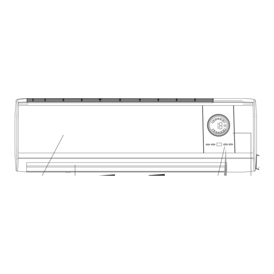
- Page 4 Air inlet Air Outlet Set Temp Wireless remote control Heat (This indicator is black for single- Cooling cooling unit). Front Panel Guide louver Receiving window Board Wall Pipe Wrapping Tape Air inlet Drainage hose Connection pipe and connection wire Indoor unit Air Outlet...
- Page 5 Overall and Installing Dimension of Indoor Unit Air inlet grill Left Tube-exit hole Top View Right Tube-exit hole Unit: mm Rear View Rear panel...
- Page 6 Overall and Installing Dimension of Indoor Unit(18K) Unit: mm above above above Bolt above Wrench...
- Page 7 Overall and Installing Dimension of Indoor Unit(24K) Unit: mm Bolt Wrench...
- Page 8 Electrical Diagram GAN GAG A180IV Electrical Diagram GAN GAG A220IV...
- Page 9 6 6 6 6 6 Manual of functions of remote controller and operation method Manual of functions of remote controller GAN A180 IV Controller Function of Indoor Unit Temperature parameters Indoor setting temperature (Tpreset) Indoor ambient temperature (Tamb.) System basic function Cooling mode In this mode, the indoor fan will run at preset fan speed.
- Page 10 3.5.3 Set TIMER ON/OFF Simultaneously If TIMER ON and TIMER OFF is set simultaneously when the system is under run status, the system will maintain its current operating status and be stopped upon the coming of preset time If TIMER ON and TIMER OFF is set simultaneously when the system is under stop status, the system will maintain its stop status.
- Page 11 Controller Function of Outdoor Unit 1 Temperature Parameters 1.1 Cooling Mode 1.1.1 Working Conditions and Process of Cooling If the compressor is in off status,and (T , start the unit in cooling mode,in which case,outdoor fan in-amb. preset and compressor start running,and microcomputer will auto adjust the frequency of compressor by cooling capacity requirements. In cooling running,if 0 ,the compressor will run at low frequency.
- Page 12 Once detected the whole unit current exeed the limit value 14. OA, that indoor temp. arrived, the unit will stop to run, the compressor stopped 3mins, will automatically resume to running status, protection times exceeds 6 times ( If compressor running time exceeds 7mins that the protection times will be cleared to 0), the system will be turned off and send the over current protection malfunction signal to indoor unit, cannot automatically resume to run, it must be press ON/OFF to turn off the unit.
- Page 14 6 6 6 6 6 Controller Function Manual Remote Controller Function Manual Applicable to: Controller Function of Indoor Unit 1 Temperature Parameters Indoor preset temperature (T preset Indoor ambient temperature (T amb. 2. Basic Functions 2.1 Cooling Mode In this mode, the indoor fan will run at preset fan speed. When the compressor stops for outdoor unit malfunction protection, the indoor fan will still run at preset fan speed.
- Page 15 3.5.3 Set TIMER ON/OFF Simultaneously If TIMER ON and TIMER OFF is set simultaneously when the system is under run status, the system will maintain its current operating status and be stopped upon the coming of preset time If TIMER ON and TIMER OFF is set simultaneously when the system is under stop status, the system will maintain its stop status.
- Page 16 Controller Function of Outdoor Unit 1 Temperature Parameters Outdoor exhaust temperature (T exhaust Outdoor ambient temperature (T out- amb. 2 Basic Functions In each mode,once started,the compressor can not be stopped until it has been running for 6 min.(excluding malfunction protection and stopping the compressor for mode switching);once stopped,the compressor should be started in 3-min.
- Page 17 2.4.3 Defrosting Process If it is detected the defoeting is required,and if the compressor running frequency is a little higher,the frequency will first reduced to some level and then the compressor and indoor fan stop,50s later,outdoor fan stops meanwhile,4-way valve stops after 45-second delay.The compressor will restart with 90Hz of running frequency in 55s to defrost.Upon defrsoting is completed,compressor running frequency will decrease to 60Hz, and 4-way valve and outdoor fan will start,10s later, compressor will run with increased frequency required by capacity.Indoor fan will run in 2 min at most.
- Page 19 7 7 7 7 7 Disassembly and Assembly Procedures Disassembly Process of Indoor Unit Operating Procedures/Photos Disassemble the Front panel Open the front panel. Firstly to screw off the screws that fixed at the guard plate on the receiving window both sides, disassemble the guard plate, then to remove the wiring terminal, then along the groove that fix the front panel to take out the front panel.
- Page 20 Operation procedures/pictures Disassemble Front Case Open the three screw covers and unscrew five screws on front case. Pull open the clasp at the front and rear sides, can remove the front panel. Disassemble the electric box cover Screws Screw cover Loosen the 3 slipknots manually, and then pull upwards the electric box cover.
- Page 21 Disassemble Electric box Tube sensor unplug the plugging connector of the Plugging connector indoor motor at the electric box, use screwdriver to unscrew the screw fixing Clasp the electric box and remove the electric box. Disassemble Evaporator Use a screwdriver to loosen the screw (1pc) of left side, (2pcs) of right side.
- Page 22 Disassembly Procedures for Outdoor Unit Operating Procedures / Photos of outdoor unit Disassemble Top Cover Top cover Screws Screw off the screws which fix the top cover, then lift it up, can take off the top cover. Disassemble the handle Screw off one screw which fix the handle, then adown to push the handle, then can take off the handle.
- Page 23 Operating Procedures / Photos of outdoor unit Disassemble the front case Screw off the screw which fix the front case, then pull it upwards, can take off the front Front case case. Screws Disassemble cabinet Screw off the screws which fix the cabinet, then can take off the cabinet.
- Page 24 Operating Procedures / Photos Disassemble Valves Screws Unscrew the two screws fixing the gas valve, unsolder the soldering point between the gas valve and the return-air duct and remove the gas valve (note: when unsoldering the soldering point, use wet cloth to completely wrap the gas valve to prevent valve body from being harmed by high temperature).
- Page 25 Operating Procedures / Photos Disassemble 4-Way Valve (Only for cooling and heating unit) Four-way valve Screw off the holding nut of the 4-way valve coil and remove the coil. Use wet cotton cloth to wrap the 4-way valve, unsold the four soldering points connecting the 4-way valve, and remove the 4-way valve.
- Page 26 Disassembly Procedure of Outdoor Unit Operating Procedures / Photos Disassemble Front Side Plate Unscrew the screws fixing the front side plate to remove it. As show in Fig.7-13: Screws Front Side Plate Fig. Disassemble Top Cover Unscrew the screws fixing the top cover, and then lift the top cover to remove it.
- Page 27 Operating Procedures / Photos Disassemble Cabinet Unscrew the screws fixing the cabinet to remove it. Screw Disassemble the electric box Screw off 4pcs screw which fix the electric Screw box, then can take off the electric box cover. Screw off 5pcs screw from electric box, pull Electric out the wire terminal of electric box, then lift it up can take off it.
- Page 28 Operating Procedures / Photos Disassemble Axial Flow Fan Unscrew the nut fixing the fan with a spanner to take out the fan . Axial Flow Fig. Disassemble Outdoor Motor Unscrew the screws fixing the motor support ,and Motor Fixing Screw then lift it upwards to remove it.
- Page 29 Operating Procedures / Photos Disassemble Capillary Unsolder the four welding points connecting the two capillary sub-asslies with the liquid valve and the condenser, and remove the capillary sub-assy. As show in Fig.7-22) Fig. Capillary Disassemble Gas Valve and Liquid Valve Liquid Valve Unscrew the four bolts fixing the two valves, unsolder the welding point connecting the gas valve...
- Page 30 Exploded View and Components and Parts List Exploded View of Indoor Unit...
- Page 31 Components and Parts List of Indoor Unit Part Code Description GAN A180IV Wall-Mounting Frame 01252004 Rear Case 22202329 Helicoid tongue 26252009 Cross Flow Fan 10352022 Evaporator Assy 010022283 Front Case 200026529 Front Panel 20002844 Water Tray 20182057 Guide Louver up 10512085 Guide Louver down 10512086...
- Page 32 Exploded View of Indoor Unit...
- Page 33 Components and Parts List of Indoor Unit Part Code Description GAN A220IV Wall-Mounting Frame 01252004 Rear Case 22202329 Helicoid tongue 26252009 Cross Flow Fan 10352022 Evaporator Assy 010022362 Front Case 200026529 Front Panel 20002844 Water Tray 20182057 Guide Louver up 10512085 Guide Louver down 10512086...
- Page 34 Exploded View of Outdoor Unit...
- Page 35 Components and Parts List of Outdoor Unit P a rt C o d e D e s c rip tio n Q ty G A G A 1 8 0 I V F ro n t G rill 0 1 4 7 3 0 0 8 F ro n t P la te 0 1 3 0 3 1 6 2 P L e ft H a n d le...
- Page 36 Exploded View of Outdoor Unit...
- Page 37 Components and Parts List of Outdoor Unit P a rt C o d e D e s c rip tio n Q ty G A G A 2 2 0 I V F ro n t G rill 0 1 4 7 3 0 0 1 H o u s in g 0 1 4 3 3 0 1 1 S m a ll H a n d le...
- Page 39 Adjust the set temperature Improper setting of temperature Check the estimated load of cooling (heating) Whether cooling (heating) load is proper Vacuumize after leakage detection Leakage or shortage of refrigerant and leakage repair. Charge refrigerant according to specification. Leakage occurs between high and Replace the compressor low pressure inside compressor Malfunction of...
- Page 41 Drainage pipe blocked or broken Change drainage pipe Water leakage Wrap of refrigerant pipe joint is not close Re-wrap and make it tight. enough. Fan of indoor unit contacts other parts. Adjust fan location. Foreign object in indoor unit Take out the foreign object. Adjust support washer of compressor, and Compressor shakes too much.
- Page 42 Processing method:Once the module malfunction happens,if it persists for a long time and can not be self- canceled, cut off the power and turn off the unit,and then re-energize the unit again after about 10 min.After repeating the procedure for sever times, if the malfunction still exists,replace the module.(refer to the next page) 8.
- Page 43 Module protection Handling method: Check if the voltage between power module P and N is too low and if the current is too high. In normal condition, voltage between P and N should be about 320V. Abnormal Check power supply circuit of outdoor unit (if PTC resistance Normal rectifying bridge, reactor, capacitance etc.