Table of Contents
Advertisement
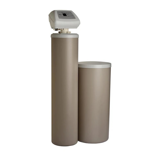
Model WHES45
How to install, operate and
maintain your Demand
Controlled Water Softener
Do not return water softener to store
If you have questions or concerns when
installing, operating or maintaining your
softener, call our toll free number:
1--866--986--3223
Monday -- Friday, 8 am -- 9 pm EST
System Tested and Certified by
NSF International against NSF/ANSI Standard 44
for softener performance.
7281453 (Rev. A 12/28/05)
Product No. 8580422
Advertisement
Table of Contents

Related Manuals for Whirlpool WHES45


Summary of Contents for Whirlpool WHES45
- Page 1 Model WHES45 How to install, operate and maintain your Demand Controlled Water Softener Do not return water softener to store If you have questions or concerns when installing, operating or maintaining your softener, call our toll free number: 1--866--986--3223 Monday -- Friday, 8 am -- 9 pm EST...
-
Page 2: Table Of Contents
Table of Contents Water Softener Safety ................Before You Start . -
Page 3: Water Softener Safety
Water Softener Safety For installations in the Commonwealth of Massachusetts: Installation by a licensed plumber is required. Plumbing code 248- - CMR of the Commonwealth of Massachusetts must be used for installation. For installations in the state of California: You must turn the Salt Efficiency Feature setting to ON. This may initiate more frequent re- charges, however, it will operate at 4,000 grains per pound of salt or higher. -
Page 4: Inspect Shipment
Inspect Shipment The parts required to assemble and install the water softener are included with the water softener. Ground clamp Single valve bypass 20 ft. drain hose Hose adaptor Hose clamps Installation adaptors Grommet Clips O- - rings Water hardness test strip Thoroughly check the water softener for possible shipping damage and parts loss. -
Page 5: Water Softener Dimensions
41---5/8” 11” 39” MODEL NOMINAL RESIN TANK SIZE WHES45 10” DIA. X 40” How a Water Softener Works Softening Cycle When the water softener is providing soft water, it is called “service” or the “softening cycle”. During this cycle, hard water flows from the main water pipe in the household into the water softener. Inside the resin tank is a bed made up of thousands of tiny, plastic beads. -
Page 6: Water Conditioning Information
Water Conditioning Information Water Conditioning Water conditioning is the treatment of four general conditions. These are: Hardness Iron Acidity Sediments 1. Hardness is a term to describe the presence of calcium and magnesium minerals in water. A chemical analysis accurately measures the amount of minerals in grain weight. For example, one gallon of water with 5 grains per gallon (gpg) hardness has dissolved minerals, that if solidified, about equals the size of one ordinary aspirin tablet. - Page 7 2. Iron in water can cause stains on clothing and plumbing fixtures. It can negatively affect the taste of food, drinking water, and other beverages. Iron in water is measured in parts per million (ppm). The total* ppm of iron, and type or types*, is determined by chemical analysis. Four different types of iron in water are: Ferrous (clear water), Ferric (red water),...
-
Page 8: Installation Requirements
Installation Requirements Tools and Parts Needed Assemble the required tools before starting installation. Read and follow the instructions provided with any tools listed here. Screwdriver Tape Measure • • Pliers • If using Soldered Copper Pipe Tubing cutter Lead- - free solder and flux •... -
Page 9: Air Gap Requirements
city water supply cold to water heater pressure tank optional sediment filter water softener well pump well water supply Figure 1 Air Gap Requirements A drain is needed for regeneration discharge water. A floor drain, close to the water softener, is preferred. -
Page 10: Plan The Installation
Plan the Installation Inlet --- Outlet Plumbing Options Always install either a single bypass valve (provided) or, if desired, parts for a 3 valve bypass system (not included) can be purchased and assembled, as shown in Figure 4. Bypass valves allow you to turn off water to the softener for maintenance if needed, but still have water in house pipes. -
Page 11: Installation
Installation Turn Off Water Supply 1. Close the main water supply valve, near the well pump or water meter. 2. Open all faucets to drain all water from the house pipes. NOTE: Be sure not to drain water from the water heater, as damage to the water heater elements could result. -
Page 12: Assemble Inlet And Outlet Plumbing
Assemble Inlet and Outlet Plumbing Install the provided grounding clamp before cutting into metallic main water piping. It should be installed on two parallel and vertical pipes (inlet and outlet) spaced so as to align with the softener connections. In some new installations where vertical pipes are not yet available, a temporary bond will need to be established prior to cutting into the water piping. -
Page 13: Install Valve Drain Hose
Soldered copper 1. Thoroughly clean and apply solder flux to all joints. 2. Make all solder connections. NOTE: Do not solder with plumbing attached to installation adaptors and single valve bypass. Soldering heat will damage the valve and adaptors. IMPORTANT: Secure ground clamp to metal pipes. Threaded pipe 1. -
Page 14: Install Salt Storage Tank Overflow Elbow And Hose
Install the Salt StorageTank Overflow Elbow and Hose 1. Install the brine tank overflow grommet and elbow in the 13/16” diameter hole in the salt storage tank sidewall. NOTE: The brine tank overflow elbow accepts either 1/2” or 3/8” I. D. hose. 2. -
Page 15: Add Water And Salt To The Salt Storage Tank
Add Water and Salt to the Salt Storage Tank 1. Using a container, add about three gallons of clean water into the salt storage tank. 2. Add salt to the salt storage tank. Use nugget, pellet or coarse solar salts with less than 1% impurities. -
Page 16: Program The Water Softener
Program the Water Softener RECHARGE button UP button Display PROGRAM button DOWN Button DATA Button Figure 11 If you have questions about installation, programming, operating and routine maintenance... call 1- - 866- - 986- - 3223, Monday - - Friday, 8 am to 9 pm, EST. When the water softener is plugged in, a model code and a test number (example: U3.0), will flash in the faceplate display. -
Page 17: Set Water Hardness Number
Set Water Hardness Number 1. Press the PROGRAM button once again to display a flashing 25 and the word “HARDNESS”. HARDNESS 2. Press the Up or Down buttons to set your water hardness number. NOTE: If your water supply contains iron, compensate for it by adding to the water hardness number. -
Page 18: Customize Features/Options
Customize Features/Options Recharge Recharge button is used to initiate an immediate recharge. Press and hold the RECHARGE button until the words “RECHARGE NOW” flash • in the display. The softener enters the fill cycle of regeneration immediately. “RECHARGE NOW’ will flash during the regeneration. When over, full water conditioning capacity is restored. -
Page 19: Data Displays
Data Displays The water softener has a DATA button to get information about your water softener. CAPACITY (remaining) - - This is the percentage of water softening capacity remaining. • Immediately after a regeneration, 100% shows. Then, as water is used, the percentage decreases until the next regeneration. -
Page 20: Regeneration (Start) Time
Regeneration (Start) Time Starting at the 2:00AM regeneration start time, the softener begins regenerations, ending approximately at 4:00AM. This is a good time in most households because water is not in use (see Automatic Bypass section). If a different time would be better for your needs, do the steps below to change the starting time. -
Page 21: Efficiency Mode
Efficiency Mode When this feature is ON, the unit will operate at salt efficiencies of 4000 grains of hardness per pound of salt or higher. (May recharge more often using smaller salt dosage and less water). When this is ON the efficiency icon will show in the lower right hand corner of the display. -
Page 22: Set Model Code
Set Model Code The model code is factory set at assembly and testing. The model code should never require resetting, but to check, or to set if previously omitted, follow the steps below. 1. Press and hold in the PROGRAM button until the Regeneration (Start) Time screen begins to flash. -
Page 23: Gallons Or Liters
Gallons or Liters All water flow rate and usage displays are in gallons with the default GALS setting. If reset to litErs, the same displays are shown in liters. 1. Press and hold in the PROGRAM button until the Regeneration (Start) Time screen begins to flash. -
Page 24: Routine Maintenance
Routine Maintenance Adding Salt Lift the salt hole cover and check the salt storage level frequently. If the conditioner uses all the salt before you add more, you will get hard water. Until you have established a refilling routine, check the salt every two or three weeks. -
Page 25: Cleaning The Nozzle And Venturi
Cleaning the Nozzle and Venturi A clean nozzle and venturi (see Figure 13) is a must for the conditioner to work properly. This small water softener creates the suction to move brine from the brine tank, into the resin tank. If it should become plugged with sand, silt, dirt, etc., the conditioner will not work, and you will get hard water. -
Page 26: Troubleshooting Guide
Troubleshooting Guide Need help troubleshooting? Call 1- - 866- - 986- - 3223, Monday - - Friday, 8 am to 9 pm, EST. Tools Needed For Most Repairs: 5/16 Hex Driver, Phillips Screwdriver, Needle ---nose Pliers PROBLEM CAUSE SOLUTION No Soft Water 1. -
Page 27: Automatic Electronic Diagnostics
Automatic Electronic Diagnostics This water softener has a self- - diagnostic function for the electrical system (except input power and/or water meter). The water softener monitors electronic components and circuits for correct operation. If a malfunction occurs, an error code appears in the display. The troubleshooting chart shows the error codes that could appear, and the possible malfunctions for each code. - Page 28 3. Symbols in the display indicate POSITION switch operation. Fill LAST RECHARGE TIME WATER MANAGEMENT SYSTEM WATER MANAGEMENT SYSTEM TURBINE TURBINE Switch is closed Switch is open (Cam rotating) (cam not rotating) 4. Use the RECHARGE button to manually advance the valve into each cycle and check correct switch operation.
-
Page 29: Manual Advance Regeneration Check
Manual Advance Regeneration Check This check verifies proper operation of the valve motor, brine tank fill, brine draw, regeneration flow rates, and other controller functions. Always make the initial checks, and the manual initiated diagnostics. NOTE: The electronic control display must show a steady time (not flashing). If an error code shows, first press the PROGRAM button to enter the diagnostic display. -
Page 30: Product Specifications
Product Specifications WHES 45 Rated Service Flow Rate (gpm) 10.0 Amount of High Capacity Resin (cu ft) 1.26 Pressure Drop at Rated Service Flow (psig) Water Supply Max. Hardness (gpg) Water Supply Max. Clear Water Iron (ppm)* Water Pressure Limits (min./max. psi) 20 --- 125 Min. -
Page 31: Wiring Schematic
This warranty gives you specific legal rights, and you may have other rights which vary from state to state. This warranty applies to consumer- -owned installations only. Registered trademark/TM Trademark of Whirlpool, U.S.A. 2006 Whirlpool Corporation. All rights reserved. -
Page 32: Softener Components
Softener Components Valve Assembly... - Page 33 Softener Components Part No. Description Part No. Description 7285130 Shroud (Incl. Key No. 2) 7155115 Brinewell Cover 7026196 Base 7082150 Wing Nut, 1/4 - - 20 7176292 Clamp Section (2) 7100819 Brinewell 7088033 Clamp Retainer (2) 7003847 O- - ring 7112963 O- - ring Seal Kit 7148875...
- Page 34 Softener Components wear- -strip seal cross- - section view...
- Page 35 Softener Components Part No. Description Part No. Description 7224087 Screw, #8-32 x 1” (2 req.) 7248722 Wire Harness (Sensor) 7250622 Motor (incl. 2 ea. of Key No. 1) 0900060 O-ring 7231393 Motor Plate 7081201 Retainer (Nozzle & Venturi) 0900857 Screw, #6-20 x 3/8 (3 req.) 7195482 Seal (Nozzle &...