
Related Manuals for AMX NetLinx NXM Series


Summary of Contents for AMX NetLinx NXM Series
- Page 1 Operation/Reference Guide NetLinx Cardframe, ® Control Cards, and NetModules NXC, NXF, and NXM Series C o n t r o l l e r s L a s t R e v i s e d : 1 /8 / 2 0 0 9...
- Page 2 AMX is not responsible for products returned without a valid RMA number. AMX Corporation is not liable for any damages caused by its products or for the failure of its products to perform. This includes any lost profits, lost savings, incidental damages, or consequential damages. AMX Corporation is not liable for any claim made by a third party or by an AMX Dealer for a third party.
- Page 3 AMX's entire liability and Licensee's exclusive remedy shall be repair or replacement of the AMX Software that does not meet AMX's Limited Warranty and which is returned to AMX. This Limited Warranty is void if failure of the AMX Software has resulted from accident, abuse, or misapplication.
-
Page 5: Table Of Contents
Table of Contents NXF CardFrame and NetModules ...1 NXF CardFrame ... 1 NXF Cardframe Specifications ... 2 Mounting Master/Hub Cards in an NXF CardFrame... 2 Setting the CardFrame's starting address... 3 Device:Port:System (D:P:S)... 3 NXS-NMS NetModules ... 4 NXS-NMS NetModules specifications ... 4 Mounting modules into an equipment rack... - Page 6 Table of Contents NXC-VAI4 Analog Voltage Control Card ...29 Specifications ... 29 Pinouts and Functions ... 30 Channel Assignments... 31 NXC-VAI4 Output Level Assignments ... 33 NXC-VAI4 Input Level Assignments ... 34 Programming Information... 34 NXC-VOL4 Volume Control Card ...41 Specifications ...
-
Page 7: Nxf Cardframe And Netmodules
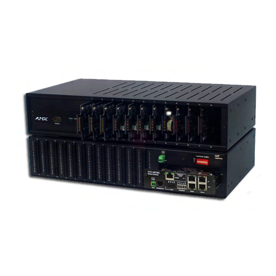
NXF CardFrame and NetModules NetLinx Control Cards can be installed in the NetLinx stand-alone operation. The NXF CardFrame accommodates a NetLinx Master (or Hub) card, up to twelve NetLinx Control cards, and provides a back plane to distribute power and data to/from the cards. The NXF CardFrame provides terminals on the rear panel for connection to the control cards and a system power supply. -
Page 8: Nxf Cardframe And Netmodules
NXF CardFrame and NetModules NXF Cardframe Specifications NXF Cardframe Specifications Power Requirement Dimensions (HWD) Weight Front Panel Components: Master/Hub Card slot Control Card slots Rack-mounting brackets Rear Panel Components: Card slots Control Card connectors (1-12) +12 VDC PWR CardFrame Number DIP switch Front faceplate Enclosure Mounting Master/Hub Cards in an NXF CardFrame... -
Page 9: Setting The Cardframe's Starting Address
Setting the CardFrame's starting address The 8-position CardFrame Number DIP switch, located on the rear of the CardFrame (FIG. 1 on page 1), sets the starting address (the device number in the D:P:S specification) for the Control Cards installed in the CardFrame. -
Page 10: Nxs-Nms Netmodules
NXF CardFrame and NetModules NXS-NMS NetModules The NXS-NMS NetModules (FG2009-10) accommodate one NetLinx Control Card, and connect to the NetLinx bus via ICSNet connections. The NetModules offer a simple and economical way to integrate additional functionality to control systems. FIG. 2 shows a NetModule shell and its main components. front NXM-NMS NetModule... -
Page 11: Installing Control Cards Into An Nxf Cardframe
Installing Control Cards into an NXF CardFrame Remove the magnetic front faceplate/viewing window from the CardFrame. Align the edge of the Control Card with a slot in the CardFrame. Slide the card into the CardFrame and press until you feel the Card seat in the backplane connector. Put the magnetic faceplate back on the CardFrame. - Page 12 NXF CardFrame and NetModules NetLinx Cardframe, Control Cards, and NetModules...
-
Page 13: Nxc-Com2 Dual Com Port Control Card
NXC-COM2 Dual COM Port Control Card The NXC-COM2 Dual COM Port Control Card (FG2022) provides two RS-232, RS-422, or RS-485 control ports and LED feedback for remote sources connected to the NetLinx CardFrame, NI-4000 or NetModule. FIG. 3 shows the COM2 card. ICSNET Status LED LED 1 LED 4... -
Page 14: Pinouts And Wiring Configuration
NXC-COM2 Dual COM Port Control Card Pinouts and Wiring Configuration NXC-COM2 Pinouts Signal Function Signal ground RXD1 Receive data TXD1 Transmit data CTS1 Clear to send RTS1 Request to send TX1+ Transmit data TX1- Transmit data RX1+ Receive data RX1- Receive data +12 VDC Power... -
Page 15: Nxc-Com2 Programming Information
NXC-COM2 Programming Information NXC-COM2 Send_Commands NXC-COM2 Send_Commands Command B9MOFF Disable 9-bit in 232/422/ 455 mode. B9MON Enable 9-bit in 232/422/455 mode. CHARD Set the delay time between all transmitted characters to the value specified (in 100 microsecond increments). CHARDM Set the delay time between all transmitted characters to the value specified (in 1 millisecond... - Page 16 NXC-COM2 Dual COM Port Control Card NXC-COM2 Send_Commands (Cont.) Command GET BAUD Get the RS-232/422/485 port’s current communication parameters. HSOFF Disable hardware handshaking (default). HSON Enable RTS (ready-to- send) and CTS (clear-to- send) hardware handshaking. RXCLR Clear all characters in the receive buffer waiting to be sent to the Master.
- Page 17 NXC-COM2 Send_Commands (Cont.) Command SET BAUD Set the RS-232/422/485 port's communication parameters. TSET BAUD Temporarily set the RS-232/422/485 port's communication parameters for a device. TXCLR Stop and clear all characters waiting in the transmit out buffer and stops transmission. XOFF Disable software handshaking (default).
-
Page 18: Nxc-Com2 Send_String Escape Sequences
NXC-COM2 Dual COM Port Control Card NXC-COM2 Send_Commands (Cont.) Command Enable software handshaking. NXC-COM2 Send_String Escape Sequences NXC-COM2 Send_String Escape Sequences Command 27,17,<time> Send a break character for a specified duration to a specific device. 27,18,0 Clear the ninth data bit by setting it to 0 on all character transmissions. - Page 19 NXC-COM2 Send_String Escape Sequences (Cont.) Command 27,20,1 Set the RTS hardware handshake's output to low/inactive (< 3V). NetLinx Cardframe, Control Cards, and NetModules NXC-COM2 Dual COM Port Control Card Description Syntax: SEND_STRING <DEV>,"27,20,1" Example: SEND_STRING RS232_1,"27,20,1" Sets the RTS hardware handshake's output to low on the RS232_1 device.
- Page 20 NXC-COM2 Dual COM Port Control Card NetLinx Cardframe, Control Cards, and NetModules...
-
Page 21: Nxc-I/O10 Input/Output Control Card
The I/Os on this card are not dry closure; they are electronic switches that float at 5V when Off. Therefore, they should not be expected to work in situations that require true dry contact (or dry closure). The I/Os do work with AMX PC1, PC2, UPC20 and UPC20+. FIG. 4 NXC-I/O10 Control card... -
Page 22: Pinouts, Signals, And I/O Mode Functions
NXC-I/O10 Input/Output Control Card Pinouts, Signals, and I/O Mode Functions NXC-I/O10 Pinouts, Signals, and I/O Mode Functions Signal SW mode Functions Common Signal ground I/O #1 Input #1 Common Signal ground I/O #2 Input #2 Common Signal ground I/O #3 Input #3 Common Signal ground... -
Page 23: Setting The Switch/Voltage Mode Jumpers
Setting the Switch/Voltage Mode Jumpers The NXC-I/O10 responds to switch closures or voltage-level (high/low) changes. Compatible I/O devices include the Power Control Sensor (PCS), tape transports and limit switches. The inputs are set for SW mode (closure) or VO mode as described below. SW (switch) Mode Senses switch or relay contact closures or provides a logic-level output. - Page 24 NXC-I/O10 Input/Output Control Card NetLinx Cardframe, Control Cards, and NetModules...
-
Page 25: Nxc-Irs4 4-Port Ir/S Control Card
NXC-IRS4 4-Port IR/S Control Card The NXC-IRS4 4-Port IR/S Control Card (FG2023) provides four IR/Serial input control ports with LED status feedback. Each port in the NXC-IRS4 stores programmed commands for IR- or serial-controlled devices. FIG. 5 shows the IRS4 card. FIG. -
Page 26: Pinouts, Signals, And Functions
NXC-IRS4 4-Port IR/S Control Card Pinouts, Signals, and Functions NXC-IRS4 Pinouts, Signals, and Functions Signal Output #1 Output #2 Output #3 Output #4 NXC-IRS4 Channel Assignments The NXC-IRS4 channel settings listed in the following table set the IR output channels. The NXC-IRS4 can process up to two IR or serial device channel setting commands simultaneously. - Page 27 NXC-IRS4 Send_Commands (Cont.) Command Send IR pulses for the selected a channel. Halt and Clear all active or buffered IR commands, and then send a single IR pulse. CTOF Set the duration of the Off time (no signal) between IR pulses for channel and IR function transmissions.
- Page 28 NXC-IRS4 4-Port IR/S Control Card NXC-IRS4 Send_Commands (Cont.) Command GET MODE Poll the IR/Serial port's configuration parameters and report the active mode settings to the device requesting the information. IROFF Halt and Clear all active or buffered IR commands being output on the designated port.
- Page 29 NXC-IRS4 Send_Commands (Cont.) Command Turn ON a device connected to an IR port based on the status of the corresponding I/O Link input. PTOF Set the time duration between power pulses in .10-second increments. PTON Set the time duration between power pulses in .10-second increments.
- Page 30 NXC-IRS4 4-Port IR/S Control Card NXC-IRS4 Send_Commands (Cont.) Command SET INPUT LINK Sets an IR device to link to an input channel for use with 'PON' and 'POF' commands. The input channel is used for power sensing (via a PCS). SET IO LINK Link an IR or Serial port to a selected I/O channel for use...
- Page 31 NXC-IRS4 Send_Commands (Cont.) Command XCHM Changes the IR output pattern for the 'XCH' send command. NetLinx Cardframe, Control Cards, and NetModules Description Syntax: SEND_COMMAND <DEV>,"'XCHM <extended channel mode>'" Variable: extended channel mode = 0 - 4. Example: SEND_COMMAND IR_1,"'XCHM 3'" Sets the IR_1 device's extended channel command to mode 3.
- Page 32 NXC-IRS4 4-Port IR/S Control Card NetLinx Cardframe, Control Cards, and NetModules...
-
Page 33: Nxc-Rel10 Relay Control Card
NXC-REL10 Relay Control Card The NXC-REL10 Relay Control Card (FG2020) provides ten relays that support devices that employ simple momentary or latching contact-closure control, with LED feedback. FIG. 6 shows the REL-10 card: FIG. 6 NXC-REL10 Relay 10 Control card Specifications NXC-REL10 Specifications Power Requirements... -
Page 34: Nxc-Rel10 Connections/Wiring
NXC-REL10 Relay Control Card NXC-REL10 Connections/Wiring The NXC-REL10 Control Card has 10 relays that are independently controlled and electrically isolated. The relay contacts are rated for a maximum of 1 A @ 0-24 VAC or 0-28 VDC (resistive). Jumpers located on the Card allow you to select Normally Open (NO) or Normally Closed (NC) contact settings: Normally open (NO) mode setting on jumper pins 1 and 2 (default). -
Page 35: Nxc-Vai4 Analog Voltage Control Card
NXC-VAI4 Analog Voltage Control Card The NXC-VAI4 Analog Voltage Control Card (FG2025) provides four independent analog-to-digital inputs and four independent digital-to-analog outputs, which are controllable over the ICSP network. Each port can be configured for a variety of DC input and output signals. The NXC-VAI4 incorporates the functionality of the AXC-VAI2 and AXC-VRG AXlink cards. -
Page 36: Pinouts And Functions
NXC-VAI4 Analog Voltage Control Card NXC-VAI4 Specifications (Cont.) I/O Status LEDs 1-8: (two LEDs per channel) LEDs light to indicate ON status. Wiring Pinouts and Functions NXC-VAI4 Pinouts, Signals, and Functions Function Output #1 (GND) Output #1 Output #2 (GND) Output #2 Output #3 (GND) Output #3... -
Page 37: Channel Assignments
Channel Assignments The channel ON/OFF assignments for the NXC-VAI4 are described in the following table. Off = 50% voltage, and all channel assignments are mutually exclusive. NXC-VAI4 Channel Assignments Channel State Channel 1 Channel 2 Channel 3 Channel 4 Channel 5 Channel 6 Channel 7 Channel 8... - Page 38 NXC-VAI4 Analog Voltage Control Card NXC-VAI4 Channel Assignments (Cont.) Channel State Channel 17 Channel 18 Channel 19 Channel 20 Channel 21 Channel 22 Channel 23 Channel 24 Channel 25 Function While channel 17 is ON, the voltage on Output 4 is set to 0% Sets Output 4 voltage to 50%.
-
Page 39: Nxc-Vai4 Output Level Assignments
NXC-VAI4 Output Level Assignments NXC-VAI4 Output Level Assignments Leve Description 8 bit field; sets voltage on Output 1 to the value commanded. The range is 0-255. Conflicts with channels 1, 5, 10, 14, 18, 22. 8 bit field; sets voltage on Output 2 to the value commanded. The range is 0-255. -
Page 40: Nxc-Vai4 Input Level Assignments
NXC-VAI4 Analog Voltage Control Card NXC-VAI4 Input Level Assignments NXC-VAI4 Input Level Assignments Level Description 8 bit field, returns the current output voltage code for Output 1 (range= 0 to 255). 8 bit field, returns the current output voltage code for Output 2 (range= 0 to 255). 8 bit field, returns the current output voltage code for Output 3 (range= 0 to 255). - Page 41 NXC-VAI4 Send_Commands (Cont.) Command Sets the slowdown distance and slowdown speed. Sets the maximum allowable deviation of final servo position when executing the GL command. This command puts the card in servo (positional) control mode. NetLinx Cardframe, Control Cards, and NetModules NXC-VAI4 Analog Voltage Control Card Description When these variables have been set, and a GL command is in progress, the...
- Page 42 NXC-VAI4 Analog Voltage Control Card NXC-VAI4 Send_Commands (Cont.) Command Sets the speed variable to be used for future positional (GL) commands. LEVOFF The NXC-VAI4 will not transmit any level value messages after the receipt of this command until the receipt of the LEVON command.
- Page 43 NXC-VAI4 Send_Commands (Cont.) Command Selects which voltage reference (if any) is to be used for scaling of the output voltage. Ramps the specified output from its current level value to the specified level value or specified percentage of maximum at the rate speci- fied by "CURRENT OUTPUT <x>...
- Page 44 NXC-VAI4 Analog Voltage Control Card NXC-VAI4 Send_Commands (Cont.) Command Sets the value of either the minimum output voltage allowed for an output, or the minimum position voltage expected for an input.· Sets the CURRENT OUTPUT <x> RAMP UP TIME and/or CURRENT OUTPUT <x>...
- Page 45 NXC-VAI4 Send_Commands (Cont.) Command Sets the value of "I/O <x> MAXIMUM" which is either the maximum output voltage allowed for an Output, or the maximum position voltage expected for an Input. Sets one of the two "set point" variables "I/O <x> SET POINT H|L"...
- Page 46 NXC-VAI4 Analog Voltage Control Card NetLinx Cardframe, Control Cards, and NetModules...
-
Page 47: Nxc-Vol4 Volume Control Card
NXC-VOL4 Volume Control Card The NXC-VOL4 Volume Control Card (FG2024) provides four discrete volume control channels with LED feedback. The volume control channels can be programmed for mono or stereo operation, and balanced or unbalanced audio connections. It supports programmable audio levels, audio mute, variable ramp speeds and preset levels. -
Page 48: Pinouts, Signals, And Functions
NXC-VOL4 Volume Control Card NXC-VOL4 Specifications (Cont.) Gain jumpers 1-4 Connections/wiring Audio Specifications Pinouts, Signals, and Functions NXC-VOL4 Pinouts, Signals, and Functions Signal Channel 1 Input 1+ Input 1- Output 1+ Output 1- Channel 2 Input 2+ Input 2- Output 2+ Output 2- Channel 3 Input 3+... -
Page 49: Nxc-Vol4 Connections/Wiring
NXC-VOL4 Connections/Wiring The NXC-VOL4 card contains four audio volume control channels. Each line-level channel is isolated from system ground and can be configured for balanced or unbalanced line operation. It supports programmable audio levels, audio mute, variable ramp speeds, and preset levels. Each audio channel's input to output gain ratio is adjustable via the on-board jumpers shown in FIG. -
Page 50: Nxc-Vol4 Levels
NXC-VOL4 Volume Control Card NXC-VOL4 Levels Volume (audio) channels 1 and 2 use levels 1 and 2 respectively. For reading current volume levels and displaying bargraphs seeCREATE_LEVEL andSEND_LEVEL. The two levels associated with each port of the NXC-VOL4 Control Card are listed in the table below: NXC-VOL4 Levels Port 1 Level... -
Page 51: Programming Information
Programming Information These NetLinx Send_Commands control the NXC-VOL4. NXC-VOL4 Send_Commands Command Ramps specified (audio) channel(s) from current level to a specified preset level or percentage at the current rate or optionally in a specified amount of time. Sets the ramp rate of the specified channel(s) where Time is the time to ramp the full range both down to up... - Page 52 NXC-VOL4 Volume Control Card NetLinx Cardframe, Control Cards, and NetModules...
- Page 53 NXC-VOL4 Volume Control Card Enter the Document Name Here...
- Page 54 It’s Your World - Take Control™ 3000 RESEARCH DRIVE, RICHARDSON, TX 75082 USA • 800.222.0193 • 469.624.8000 • 469-624-7153 fax • 800.932.6993 technical support • www.amx.com...