Carrier 50SD Install And Operation Instructions
Single packaged electric cooling units sizes 024-060
Hide thumbs
Also See for 50SD:
- Operating and maintenance manual (4 pages) ,
- Owner's information manual (4 pages)
Table of Contents
Advertisement
Quick Links
Visit www.carrier.com
Installation, Start-Up, and Operating Instructions
NOTE: Read the entire instruction manual before starting the
installation.
This symbol → indicates a change since the last issue.
TABLE OF CONTENTS
SAFETY CONSIDERATIONS .....................................................1
INTRODUCTION ..........................................................................2
RECEIVING AND INSTALLATION ..........................................2
Check Equipment......................................................................2
IDENTIFY UNIT ................................................................2
INSPECT SHIPMENT ........................................................2
Provide Unit Support ................................................................2
ROOF CURB.......................................................................2
SLAB MOUNT ...................................................................2
GROUND MOUNT ............................................................2
Provide Clearances....................................................................2
Field Fabricate Ductwork .........................................................2
Rig and Place Unit....................................................................2
INSPECTION ......................................................................4
INSTALLATION ................................................................4
Connect Condensate Drain .......................................................7
Install Duct Connections ..........................................................7
CAL) DISCHARGE ............................................................7
Install Electrical Connection ....................................................9
HIGH-VOLTAGE CONNECTIONS..................................9
CONTROL VOLTAGE CONNECTIONS.........................9
STANDARD CONNECTION ..........................................10
TRANSFORMER PROTECTION....................................12
PRE-START-UP ..........................................................................12
START-UP ...................................................................................12
CHECK FOR REFRIGERANT LEAKS..........................12
MENTS ..............................................................................12
CHECKING COOLING CONTROL OPERATION .......12
CHARGE ...........................................................................12
MENTS ..............................................................................14
For 208/230V.....................................................................14
COOLING SEQUENCE OF OPERATION.....................14
MAINTENANCE.........................................................................14
AIR FILTER......................................................................15
EVAPORATOR BLOWER AND MOTOR.....................15
DENSATE DRAIN PAN ..................................................16
CONDENSER FAN ..........................................................16
ELECTRICAL CONTROLS AND WIRING ..................16
REFRIGERANT CIRCUIT...............................................16
EVAPORATOR AIRFLOW .............................................17
METERING DEVICE - ACCURATER ........................17
Manufacturer reserves the right to discontinue, or change at any time, specifications or designs without notice and without incurring obligations.
Book 1 6
PC 101
Tab
6 8
Single Packaged Electric Cooling Units
Sizes 024-060
Printed in U.S.A.
Catalog No. 50SD-1SI
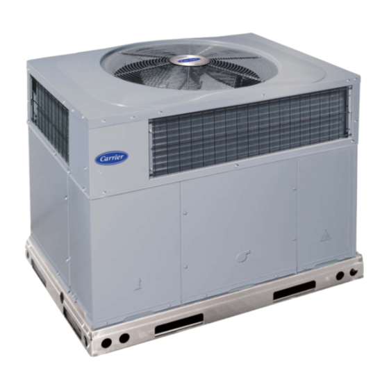
Fig. 1-Model 50SD
TROUBLESHOOTING ...............................................................17
START-UP CHECKLIST............................................................17
NOTE TO INSTALLER - Before the installation, READ THESE
INSTRUCTIONS CAREFULLY AND COMPLETELY. Also,
make sure the User's Manual and Replacement Guide are left with
the unit after installation.
SAFETY CONSIDERATIONS
Installation and servicing of air-conditioning equipment can be
hazardous due to system pressure and electrical components. Only
trained and qualified personnel should install, repair, or service
air-conditioning equipment.
Untrained personnel can perform basic maintenance functions of
cleaning coils and filters. All other operations should be performed
by trained service personnel. When working on air-conditioning
equipment, observe precautions in the literature, tags, and labels
attached to the unit, and other safety precautions that may apply.
Follow all safety codes. Wear safety glasses and work gloves. Use
quenching cloth for unbrazing operations. Have fire extinguisher
available for all brazing operations. Consult a qualified installer or
service agency for information or assistance. The qualified in-
staller or agency must use only factory-authorized kits or acces-
sories when modifying this product.
Pg 1
50SD
C99001
8-05
Replaces: New
Advertisement
Table of Contents

Related Manuals for Carrier 50SD


Summary of Contents for Carrier 50SD
-
Page 1: Table Of Contents
Field Fabricate Ductwork ............2 Rig and Place Unit..............2 INSPECTION ..............4 INSTALLATION ..............4 C99001 Connect Condensate Drain ............7 Fig. 1—Model 50SD Install Duct Connections ............7 CONFIGURING UNITS FOR DOWNFLOW (VERTI- CAL) DISCHARGE ............7 TROUBLESHOOTING ...............17 Install Electrical Connection ............9 HIGH-VOLTAGE CONNECTIONS........9 START-UP CHECKLIST............17... -
Page 2: Sizes
INTRODUCTION at either the outdoor-air inlet or the fan discharge may be The 50SD unit (see Fig. 1) is fully self-contained, and designed for detrimental to compressor life. outdoor installation. See Figs. 2 and 3 for unit dimensions. All unit... - Page 3 REQUIRED CLEARANCE TO COMBUSTIBLE MATL. REQUIRED CLEARANCE FOR OPERATION AND SERVICING INCHES [mm] (R efer to M aximum O perating C learances ) EVAP. COIL ACCESS SIDE............36.00 [914.0] INCHES [mm] POWER ENTRY SIDE..............42.00 [1066.8] TOP OF UNIT...................14.00 [355.6] (EXCEPT FOR NEC REQUIREMENTS) DUCT SIDE OF UNIT.................2.00 [50.8] UNIT TOP ..................48.00 [1219.2] SIDE OPPOSITE DUCTS ..............14.00 [355.6]...
-
Page 4: Inspection
REQUIRED CLEARANCE FOR OPERATION AND SERVICING REQUIRED CLEARANCE TO COMBUSTIBLE MATL. INCHES [mm] (R efer to M aximum O perating C learances ) EVAP. COIL ACCESS SIDE............36.00 [914.0] INCHES [mm] POWER ENTRY SIDE..............42.00 [1066.8] TOP OF UNIT...................14.00 [355.6] (EXCEPT FOR NEC REQUIREMENTS) DUCT SIDE OF UNIT.................2.00 [50.8] UNIT TOP ..................48.00 [1219.2] SIDE OPPOSITE DUCTS ..............14.00 [355.6]... -
Page 5: Installation
HVAC unit HVAC unit base base Gask eting inner flange* Scre w Scre w Gask eting (NO TE A) inner flange* (NO TE A) *Gask eting *Gask eting outer flange outer flange Wood nailer* Wood nailer* Flashing field Flashing field supplied supplied Roofcurb*... -
Page 6: Connect Condensate Drain
See Fig. 2 & 3 for comply with local codes and restrictions. connection sizes and locations. Model 50SD disposes of condensate water through a 3/4 in. NPT IMPORTANT: Use flexible connectors between ductwork and fitting which exits through the base on the evaporator coil access unit to prevent transmission of vibration. -
Page 7: Configuring Units For Downflow (Verti- Cal) Discharge
OPTIONAL OPTIONAL RETURN SUPPLY OPENING OPENING 2" EVAP. COIL COND. COIL C99096 Fig. 5B—Slab Mounting Detail DETAIL A C99066 MAXIMUM WEIGHT SIZE UNIT 50SD 20.0 508.0 19.3 490.2 20.0 508.0 14.0 355.6 21.0 533.4 20.5 520.7 21.0 533.4 20.5 520.7 21.0... - Page 8 Table 1—Physical Data—Unit 50SD UNIT SIZE NOMINAL CAPACITY (ton) 2-1/2 3-1/2 OPERATING WEIGHT (lb.) COMPRESSOR Scroll REFRIGERANT (R-22) 10.9 10.9 12.3 12.0 Quantity (lb.) Accurater REFRIGERANT METERING DEVICE Orifice ID (in.) 0.065 0.070 0.080 0.088 0.088 0.101 CONDENSER COIL 2...21 2...21...
-
Page 9: Install Electrical Connection
Table 2—Minimum Airflow for Safe Electric Heater Operation (Cfm) SIZE 1000 1200 1400 1600 1750 INSTALLATION REQUIREMENTS Failure to follow these precautions may result in damage to the unit being installed: 1. Make all electrical connections in accordance with NEC ANSI/NFPA (latest edition) and local electrical codes governing such wiring. - Page 10 Table 3—Electrical Data—50SD VOLTAGE ELECTRIC HEAT COMPRESSOR POWER SUPPLY RANGE (SINGLE POINT CONNECTION) UNIT V-PH-HZ Max Fuse SIZE Nominal Kw MOCP Ckt Bkr 16.5/16.5 20/20 — 3.8/5.0 18.1/20.8 25.1/28.5 30/30 — 208/230–1–60 10.9 54.0 7.5/10.0 36.1/41.7 47.6/54.6 50/60 — 5.4/7.2 26.0/30.0...
-
Page 11: Standard Connection
between the thermostat and the unit. If the thermostat is located c. Inspect all field- and factory-wiring connections. Be sure more than 100 ft. from the unit (as measured along the control that connections are completed and tight. voltage wires), use no. 16 AWG color-coded, insulated (35 C d. - Page 12 A05112 Fig. 12—Wiring Diagram (208/230-60-1)
-
Page 13: Checking And Adjusting Refrigerant
Do not All 50SD units are factory wired for low speed, except sizes 030 use mercury or small dial-type thermometers because they are not and 048 which are wired for medium speed. -
Page 14: Maintenance
A05109 Fig. 13—Cooling Charging Chart NOTE: Once the compressor has started and then has stopped, it should not be started again until 5 minutes have elapsed. FIRE, EXPLOSION, ELECTRICAL SHOCK HAZARD The cooling cycle remains “on” until the room temperature drops Failure to follow this warning could result in personal injury, to a point that is slightly below the cooling control setting of the death or property damage. -
Page 15: Air Filter
d. Ensure proper reassembly by marking blower wheel and motor in relation to blower housing before disassembly. EQUIPMENT DAMAGE HAZARD e. Loosen setscrew(s) that secures wheel to motor shaft, Failure to follow this caution may result in unit component remove screws that secure motor mount brackets to hous- damage. - Page 16 Table 5—Wet Coil Air Delivery (Deduct 10 percent for 208v)* Horizontal and Downflow Discharge Unit 50SD024-060 230 VOLT External Static Pressure (in. wg) Motor Unit Speed Watts — — — — — — — — — — Watts — — —...
-
Page 17: Checking And Adjusting Refrigerant Charge
2. Turn motor/grille assembly upside down on top cover to expose the fan blade. EXPLOSION, PERSONAL INJURY HAZARD 3. Inspect the fan blades for cracks or bends. Failuire to follow this warning could result in personal injury, 4. If fan needs to be removed, loosen the setscrew and slide the death, or property damage. - Page 18 Table 6—Troubleshooting—Cooling SYMPTOM CAUSE REMEDY Power Failure Call power company Fuse blown or circuit breaker tripped Replace fuse or reset circuit breaker Defective thermostat, contractor, transformer, or Replace component control relay Compressor and condenser fan will not start. Insufficient line voltage Determine cause and correct Incorrect or faulty wiring Check wiring diagram and rewire correctly...
- Page 19 START-UP CHECKLIST (REMOVE AND STORE IN JOB FILE) I. PRELIMINARY INFORMATION Model No ................................Serial No ................................Date ..................................Technician ................................Job/ Location............................... II. PRE-START-UP ____ Verify that all packing materials have been removed from unit ____ Verify that condensate connection is installed per installation instructions ____ Check all electrical connections and terminals for tightness ____ Check that indoor (evaporator) air filter is clean and in place ____ Verify that unit installation is level...
- Page 20 Copyright 2005 CARRIER Corp. • 7310 W. Morris St. • Indianapolis, IN 46231 Manufacturer reserves the right to discontinue, or change at any time, specifications or designs without notice and without incurring obligations. Book 1 6 PC 101 Printed in U.S.A.