Table of Contents
Advertisement
50ZP
10 SEER Single Packaged Air Conditioner
2---5 Nominal Tons (Sizes 024---060)
NOTE: Read the entire instruction manual before starting the
installation.
TABLE OF CONTENTS
SAFETY CONSIDERATIONS
. . . . . . . . . . . . . . . . . . . . . . . . . . . . . . . . . . . . . . . . . .
. . . . . . . . . . . . . . . . . . . . . . . . . . . . . . . . . .
. . . . . . . . . . . . . . . . . . . . . . . . . . . . . . . . . . . .
. . . . . . . . . . . . . . . . . . . . . . . . . . . . . . . . .
. . . . . . . . . . . . . . . . . . . . . . . . . . . . . . .
. . . . . . . . . . . . . . . . . . . . . . . . . . . . . . . . . . . . .
. . . . . . . . . . . . . . . . . . . . . . . . . . . . . . . . .
. . . . . . . . . . . . . . . . . . . . . . . . . . . . . . . . . . . . . . . .
. . . . . . . . . . . . . . . . . . . . . . . . . . . . . . . . . . . . . .
. . . . . . . . . . . . . . . . . . . . . . . . . . . . . . . . . . . .
. . . . . . . . . . . . . . . . . . . . . . . . . . . . . . . . . . . . .
. . . . . . . . . . . . . . . . . . . . . . . . . . . . . . . .
. . . . . . . . . . . . . . . . . . . . . . . . . . . . . .
. . . . . . . . . . . . . . . . . . . . . . . . . . . .
NOTE:
TO INSTALLER - - Before the installation , READ
THESE INSTRUCTIONS CAREFULLY AND COMPLETELY.
Also, make sure the User's Manual is left with the unit after
installation.
SAFETY CONSIDERATIONS
Improper installation adjustment, alteration, service, maintenance,
or use can cause explosion, fire, electrical shock, or other
conditions which may cause death, personal injury, or property
damage. Consult a qualified installer, service agency, or your
distributor or branch for information or assistance. The qualified
installer or agency must use factory- -authorized kits or accessories
when modifying this product Refer to the individual instructions
packaged with the kits or accessories when installing.
Installation Instructions
. . . . . . . . . . . . . . . . . . . . . . . . .
. . . . . . . . . . . . . . . . . .
. . . . . . . . . . . . . . . . . . . . . . . . . . .
. . . . . . . . . . . . . . . . . . . . . .
. . . . . . . . . . . . . . . . . . . . . . . . .
. . . . . . . . . . . . . . . . . . . . . . . . . .
. . . . . . . . . . . . . . . . . . . . . .
. . . . . . . . . . . . . .
. . . . . . . . . . . . . . . . . . . . . . .
. . . . . . . . . . . . . . .
PAGE
1
2
5- -8
5
5
5
5
5
5
5
5
Follow all safety codes. Wear safety glasses, protective clothing,
and work gloves. Use quenching cloth for brazing operations.
.
Have a fire extinguisher available. Read these instructions
thoroughly and follow all warnings or cautions included in
6
literature and attached to the unit. Consult local building codes, the
6
current editions of the National Electrical Code (NEC) NFPA 70.
8
In Canada refer to the current editions of the Canadian Electrical
8
Code CSA C22.1.
8
Recognize safety information. This is the safety- -alert symbol
8
When you see this symbol on the unit and in instructions or
8
manuals, be alert to the potential for personal injury. Understand
8
these signal words; DANGER, WARNING, and CAUTION. These
words are used with the safety- -alert symbol. DANGER identifies
9
the most serious hazards which will result in severe personal injury
10- -12
or death. WARNING signifies hazards which could result in
12- -14
personal injury or death. CAUTION is used to identify unsafe
14
practices which may result in minor personal injury or product and
14
property damage. NOTE is used to highlight suggestions which
will result in enhanced installation, reliability, or operation.
!
ELECTRICAL SHOCK HAZARD
Failure to follow this warning could result in personal
injury or death.
Before installing or servicing system, always turn off main
power to system and install lockout tag. There may be
more than one disconnect switch.
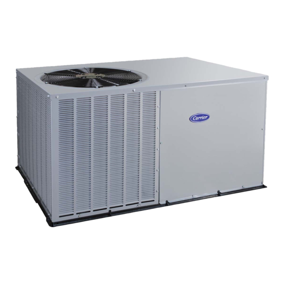
1
Fig. 1 - - 50ZP (Size 036 Shown)
WARNING
C00001
.
Advertisement
Table of Contents

Related Manuals for Carrier 50ZP024


Summary of Contents for Carrier 50ZP024
-
Page 1: Table Of Contents
50ZP 10 SEER Single Packaged Air Conditioner 2---5 Nominal Tons (Sizes 024---060) Installation Instructions NOTE: Read the entire instruction manual before starting the installation. TABLE OF CONTENTS PAGE SAFETY CONSIDERATIONS ......General . - Page 2 1.20 19.61 2.50 [30.6] [498.1] [63.5] 1.0540 I.D x .50 DEEP [26.772 x 12.7] C00002 Fig. 2 - - Base Unit Dimensions, 50ZP024- -036 UNIT WEIGHT CENTER OF GRAVITY IN. (MM) UNIT ELECTRICAL CHARACTERISTICS 355.6 508.0 241.3 50ZP024 208/230- -1- -60 (14.00)
- Page 3 16.06 11.57 [294.0] [408.0] REQUIRED CLEARANCE TO COMBUSTIBLE MA TL. INCHES [mm] TOP OF UNIT..................0 DUCT SIDE OF UNIT................0 SIDE OPPOSITE DUCTS ..............0 BOTTOM OF UNIT .................0 NEC. REQUIRED CLEARANCES. INCHES [mm] BETWEEN UNITS, POWER ENTRY SIDE ........42.00 [1066.8] UNIT AND UNGROUNDED SURFACES, POWER ENTRY SIDE .36.00 [914.0] UNIT AND BLOCK OR CONCRETE WALLS AND OTHER GROUNDED SURFACES, POWER ENTRY SIDE......42.00 [1066.8] REQUIRED CLEARANCE FOR OPERATION AND SERVICING...
- Page 4 DIMENSIONS IN [ ] ARE IN mm 13.89 REQUIRED CLEARANCE TO COMBUSTIBLE MA TL. [352.7] INCHES [mm] 13.89 4.63 2.11 TOP OF UNIT..................0 [352.8] [117.6] [53.7] DUCT SIDE OF UNIT................0 SIDE OPPOSITE DUCTS ..............0 BOTTOM OF UNIT .................0 NEC. REQUIRED CLEARANCES. INCHES [mm] BETWEEN UNITS, POWER ENTRY SIDE ........42.00 [1066.8] UNIT AND UNGROUNDED SURFACES, POWER ENTRY SIDE .36.00 [914.0]...
-
Page 5: General
Check all items against shipping list. Immediately notify the 1. Five pieces of flange are shipped on the return- -air opening nearest Carrier Air Conditioning office if any item is missing. of the unit. Remove the flanges from the shipping position. -
Page 6: Converting Horizontal Discharge Units To Downflow (Vertical) Discharge
Converting Horizontal Discharge Units to Downflow S Size ductwork for cooling air quantity (CFM). (Vertical) Discharge S Insulate and weatherproof all external ductwork. Insulate and cover with a vapor barrier all ductwork passing through WARNING conditioned spaces. Follow latest Sheet Metal and Air Conditioning Contractors National Association (SMACNA) and Air Conditioning Contractors Association (ACCA) minimum ELECTRICAL SHOCK HAZARD... - Page 7 Table 1 – Physical Data UNIT 50ZP SHIPPING WEIGHT (lbs) (kg) COMPRESSOR TYPE Reciprocating REFRIGERANT R-22 Charge (lb) (kg) REFRIGERANT METERING DEVICE Acutrol™ Device CONDENSER COIL Copper Tubes, Aluminum Plate Fins 1...17 1...17 2...17 1...17 2...17 2...17 Rows...Fins/in. 11.1 10.7 Face Area (sq ft) CONDENSER-FAN Propeller...
-
Page 8: Install Electrical Connections
Condensate water can be drained directly onto the roof in rooftop The field- -supplied disconnect may be mounted on the unit over installations (where permitted) or onto a gravel apron in ground the high- -voltage inlet hole. See Fig. 2- -4. level installations. -
Page 9: Special Procedures For 208- -V Operation
PRE- - START- - UP ROUTING CONTROL POWER WIRES — Form a drip- -loop with the thermostat leads before routing them into the unit. Route the thermostat leads through grommeted hole provided in unit (see WARNING Fig. 10) into unit control box. Connect thermostat leads to unit control power leads as shown in Fig. - Page 10 Table 1). Refer to Carrier Refrigerant Service Techniques blower motor. Manual, Refrigerants section. Units 50ZP024,036,048, and 060 blower motors are factory wired Unit panels must be in place when unit is operating during for low speed operation. Units 50ZP030 and 042 are factory wired charging procedure.
- Page 11 ° F ° C ° F ° C ° ° C00015 C00017 Fig. 14 - - Cooling Charging Chart, 50ZP024 Fig. 16 - - Cooling Charging Chart, 50ZP036 Units OUTDOOR TEMP OUTDOOR TEMP ° F ° C ° F ° C °...
-
Page 12: Maintenance
Step 6 — Sequence of Operation FAN OPERATION — The FAN switch on the thermostat controls OUTDOOR TEMP ° F ° C indoor fan operation. When the FAN switch is placed in the ON position, the IFR (indoor- -fan relay) is energized through the G terminal on the thermostat. - Page 13 Step 3 — Evaporator Blower and Motor WARNING For longer life, operating economy, and continuing efficiency, clean accumulated dirt and grease from the blower wheel and ELECTRICAL SHOCK HAZARD motor annually. Failure to follow these warnings could result in personal WARNING injury or death: 1.
-
Page 14: Troubleshooting
Step 8 — Evaporator Airflow foreign matter from the pan. Flush the pan and drain tube with clear water. Do not splash water on the insulation, motor, wiring, or The cooling airflow does not require checking unless improper air filter(s). If the drain tube is restricted, clear it with a “plumbers performance is suspected. - Page 15 Table 2 – Dry Coil Air Delivery* Horizontal Discharge (Deduct 10% for 208 Volt Operation) External Static Pressure (IN. W.C.) Motor Unit Speed Delivery Watts Watts 1131 1090 1038 Watts High 1391 1338 1285 1200 1115 1018 Watts Watts 1131 1090 1038 Watts...
- Page 16 A10093 Fig. 21 - - 50ZP 208/230- -1 Wiring Diagram...
- Page 17 A10094 Fig. 22 - - 50ZP 208/230- -3 Wiring Diagram...
- Page 18 Table 5 – Troubleshooting Chart SYMPTOM CAUSE REMEDY Power failure Call power company Fuse blown or circuit breaker tripped Replace fuse or reset circuit breaker Defective contactor, transformer, control relay, or Replace component Compressor and outdoor fan high--pressure, or low--pressure switch will not start Insufficient line voltage Determine cause and correct...
- Page 19 START- -UP CHECKLIST (REMOVE AND STORE IN JOB FILE) I. PRELIMINARY INFORMATION Model No ................................Serial No ................................Date ..................................Technician ................................Customer Information(Name/Address) ........................II. PRE- -START- -UP ____ Verify that all packing materials have been removed from unit. ____ Verify that condensate connection is installed per installation instructions.
- Page 20 Catalog No: 50ZP---06SI Copyright 2010 Carrier Corp. S 7310 W. Morris St. S Indianapolis, IN 46231 Printed in U.S.A. Edition Date: 02/10 Manufacturer reserves the right to change, at any time, specifications and designs without notice and without obligations. Replaces: 50ZP--- 4SI...