Table of Contents
Advertisement
Visit www.carrier.com
Installation, Start-Up, and Operating Instructions
NOTE: Read the entire instruction manual before starting the
installation.
TABLE OF CONTENTS
SAFETY CONSIDERATIONS .....................................................1
INTRODUCTION ..........................................................................2
RECEIVING AND INSTALLATION ..........................................2
ICM FIOP PRE-START-UP..........................................................2
Electrical Connections ..............................................................2
Control Voltage Connections ..............................................2
Standard Connection............................................................2
Easy Select™-48GP..........................................................2
48GP Sequence of Operation..............................................4
Easy Select™-48JZ...........................................................5
48JZ Sequence of Operation...............................................7
Easy Select™-50GL & 50JZ............................................7
50GL & 50JZ Sequence Of Operation...............................9
ICM FIOP START-UP ................................................................10
48GP Start-Up (ICM FIOP) ...................................................10
48JZ Start-Up (ICM FIOP) ....................................................10
50GL: Start-Up (ICM FIOP)..................................................11
50JZ: Start-Up (ICM FIOP) ...................................................11
ELECTRICAL DATA & SCHEMATICS-ICM FIOP.............12
Physical Data & Electrical Schematics..................................12
Tables For System Set-Up......................................................12
CARE AND MAINTENANCE...................................................12
TROUBLESHOOTING ...............................................................13
START-UP CHECKLIST............................................................13
NOTE TO INSTALLER - READ THESE INSTRUCTIONS
CAREFULLY AND COMPLETELY before installing this unit.
Also, make sure the Owner's Manual and Service Instructions are
left with the unit after installation.
SAFETY CONSIDERATIONS
Installation and servicing of air-conditioning equipment can be
hazardous due to system pressure and electrical components. Only
trained and qualified personnel should install, repair, or service
air-conditioning equipment.
Untrained personnel can perform basic maintenance functions of
cleaning coils and filters. All other operations should be performed
by trained service personnel. When working on air-conditioning
equipment, observe precautions in the literature, tags, and labels
attached to the unit, and other safety precautions that may apply.
Follow all safety codes. Wear safety glasses and work gloves. Use
quenching cloth for unbrazing operations. Have fire extinguisher
available for all brazing operations.
Manufacturer reserves the right to discontinue, or change at any time, specifications or designs without notice and without incurring obligations.
Book 1 4
PC 101
Catalog No. 534-80085
Tab 1a 1a
48GP (N) 024-060, 48JZ (N) 024-060
50GL 024-060, 50JZ 024-060
ICM FIOP Installation Instructions
Improper installation, adjustment, alteration, service, mainte-
nance, or use can cause explosion, fire, electric shock, or
other occurrences, which could cause serious injury or death
or damage your property. Consult a qualified installer or
service agency for information or assistance. The qualified
installer or agency must use only factory-authorized kits or
accessories when modifying this product.
Recognize safety information. This is the safety-alert symbol
When you see this symbol on the product or in instructions or
manuals, be alert to the potential for personal injury.
Understand the signal words - DANGER, WARNING, CAU-
TION, and NOTE. Danger identifies the most serious hazards,
which will result in severe personal injury or death. Warning
indicates a condition that could cause serious personal injury or
death. Caution is used to identify unsafe practices, which would
result in minor personal injury or product and property damage.
NOTE is used to highlight suggestions which will result in
enhanced installation, reliability, or operation.
The power supply (volts, phase, and hertz) must correspond to that
specified on unit rating plate.
The electrical supply provided by the utility must be sufficient to
handle load imposed by this unit. Electrical supply must match the
voltage requirements listed on unit rating plate.
This installation must conform with local building codes and with
NEC (National Electrical Code). Refer to provincial and local
plumbing or waste water codes and other applicable local codes.
Printed in U.S.A.
Form 48-21SI
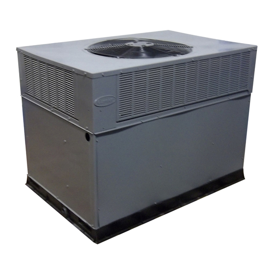
Fig. 1-Puron® Unit (48GP Shown)
Pg 1
10-01
C99088
.
Replaces: 48-20SI
Advertisement
Table of Contents

Related Manuals for Carrier 48GP (N) 024-060


Summary of Contents for Carrier 48GP (N) 024-060
-
Page 1: Table Of Contents
Manufacturer reserves the right to discontinue, or change at any time, specifications or designs without notice and without incurring obligations. Book 1 4 PC 101 Catalog No. 534-80085 Tab 1a 1a 48GP (N) 024-060, 48JZ (N) 024-060 50GL 024-060, 50JZ 024-060 ICM FIOP Installation Instructions Fig. 1—Puron® Unit (48GP Shown) Improper installation, adjustment, alteration, service, mainte-... -
Page 2: Introduction
ICM motor option is 55°F. To operate in cooling at lower ambients the Motor Master™ II low ambient kit is required. These instructions cover the installation of a Carrier Small Packaged Product with ICM motor-factory installed option (FIOP). This option can be selected as a FIOP on gas heating/electric cooling (48GP), dual fuel–electric heat pump with... - Page 3 POWER SUPPLY Factory selected air conditioner size should correspond to capacity of unit installed. Installer should verify air conditioner size to ensure that airflow delivered falls within proper range for the size unit installed. This applies to all operational modes.
-
Page 4: 48Gp Sequence Of Operation
(2.) AC/HP Size-Factory selected to match system size, please verify. (3.) SYSTEM TYPE-Factory selected on 48GP system AC- AIR CONDITIONER. (4.) AC/HP CFM ADJUST-Select HIGH for 042 & 048, NOM for 036 & 060, and LO for 024 & 030.. -
Page 5: Easy Select™-48Jz
“On” delay and a 45 sec. “Off” delay. EASY SELECT™—48JZ NOTE: Either the Carrier Thermidistat™ or Dual Fuel ther- mostat is required for operation of the dual-fuel (48JZ) units. Be sure to follow the installation instructions supplied with the Thermidistat™. - Page 6 (4.) ENH (enhanced) selection provides a 30 sec. cooling & heat pump on delay with no airflow, plus 150 seconds at 70 percent airflow and no off delay for added comfort. This will minimize cold blow in heat pump operation and could enhance system efficiency.
-
Page 7: 48Jz Sequence Of Operation
to a level which causes the Thermidistat™ to close its contacts. When the contacts close, the airflow will return to 100 percent of selected cooling airflow. To activate this mode wire in Thermidistat™ see jumper in Fig. 10. e. DEHUMIDIFY AND SUPER DEHUMIDIFY CAPABILITIES This model unit is capable of responding to a signal from Thermidistat™... - Page 8 (See Fig. 11, A as indicated). b. AC/HP SIZE—SELECT SYSTEM SIZE INSTALLED The factory setting for air conditioner or heat pump size is the size which matches the model of packaged unit installed. Installer should verify air conditioner or heat pump size to ensure that airflow delivered falls within proper range for the size unit installed.
-
Page 9: 50Gl & 50Jz Sequence Of Operation
This configuration provides the following comfort enhance- ments: (a.) A 30 sec blower on delay with 150 sec at 70 percent airflow to allow the indoor coil to warm up or cool down before the blower is asked to deliver 100 percent airflow reducing the cold blow sensation at start up in heating and allowing the indoor coil to more quickly reach wet coil operating conditions in cooling. -
Page 10: Icm Fiop Start-Up
value. If circuit R to G is open (0–v.) for super dehumidify mode, the motor delivers reduced airflow to maximize the humidity removal of the system while minimizing over cooling. e. ELECTRIC HEATING MODE (1.) Thermostat closes circuit R to W/W1, or W2—The unit delivers the selected electric heat airflow. -
Page 11: 50Gl: Start-Up (Icm Fiop)
(2.) COOLING MODE— Press MODE button on the Thermidistat™ until COOL icon is displayed. Cooling begins within 10 sec. and remains on for 4 minutes. Observe that compressor, outdoor fan and indoor blower motors start after the call for Cooling. At the end of 4 minutes, the cooling cycle stops and the MODE reverts back to OFF. -
Page 12: Electrical Data & Schematics-Icm Fiop
ELECTRICAL DATA & SCHEMATICS—ICM FIOP Step 1—Physical Data & Electrical Schematics Use the Physical Data and Electrical Tables on the following pages for information that applies to Carrier Puron® units with the ICM indoor motor FIOP. AIRFLOW & TEMPERATURE RISE TABLES—ICM FIOP Step 2—Tables For System Set-Up... -
Page 13: Troubleshooting
Table 2—ICM FIOP Physical Data—Unit 48GP (Continued) THIS DATA APPLIES TO 48GP UNITS WITH THE ICM INDOOR MOTOR FIOP UNIT SIZE 48GP NOMINAL CAPACITY (ton) OPERATING WEIGHT (lb.) COMPRESSORS Quantity REFRIGERANT (R-410A) Quantity (lb.) REFRIGERANT METERING DEVICE Orifice ID (in.) AccuRater™... - Page 14 C01035 Fig. 14—ICM FIOP Electric Schematic—Unit 48GP...
- Page 15 Table 4—ICM FIOP Physical Data—Unit 48JZ THIS DATA APPLIES TO 48JZ UNITS WITH THE ICM INDOOR MOTOR FIOP UNIT SIZE 48JZ NOMINAL CAPACITY (ton) OPERATING WEIGHT (lb.) COMPRESSORS Quantity REFRIGERANT (R-410A) Quantity (lb.) REFRIGERANT METERING DEVICE Orifice Indoor (in.) AccuRater™ Piston REFRIGERANT METERING DEVICE Orifice Outdoor (in.) AccuRater™...
- Page 16 Table 5—ICM FIOP Physical Data—Unit 48JZ (Continued) THIS DATA APPLIES TO 48JZ UNITS WITH THE ICM INDOOR MOTOR FIOP UNIT SIZE 48JZ NOMINAL CAPACITY (ton) OPERATING WEIGHT (lb.) COMPRESSORS Quantity REFRIGERANT (R-410A) Quantity (lb.) REFRIGERANT METERING DEVICE Orifice Indoor (in.) AccuRater™...
- Page 17 C01101 Fig. 15—ICM FIOP Electric Schematic—Unit 48JZ...
- Page 18 Table 7—ICM FIOP Physical Data—Unit 50GL THIS DATA APPLIES TO 50GL UNITS WITH THE ICM INDOOR MOTOR FIOP UNIT SIZE NOMINAL CAPACITY (ton) OPERATING WEIGHT (lb) COMPRESSOR REFRIGERANT (R-410A) Quantity (lb) REFRIGERANT METERING DEVICE Orifice ID (in.) CONDENSER COIL Rows...Fins/in. Face Area (sq.
- Page 19 Table 8—50GL with ICM FIOP Electrical Data VOLTAGE COMPRESSOR RANGE UNIT V-PH-HZ SIZE 50GL MIN MAX 208/230–1–60 187 208/230–1–60 187 208/230–1–60 187 208/230–1–60 187 208/230–1–60 187 208/230–1–60 187 * Heater capacity (kW) based on heater voltage of 208-v & 240-v. If power distribution voltage to unit varies from rated heater voltage, heater kW will vary accordingly. Refer to Multiplication Factors Table 23.
- Page 20 C01037 Fig. 16—ICM FIOP Electrical Schematic—50GL...
- Page 21 Table 9—ICM FIOP Physical Data—Unit 50JZ THIS DATA APPLIES TO 50JZ UNITS WITH THE ICM INDOOR MOTOR FIOP UNIT SIZE NOMINAL CAPACITY (ton) OPERATING WEIGHT (lb.) COMPRESSOR QUANTITY TYPE REFRIGERANT REFRIGERANT METERING DEVICE Refrigerant (R-410A) Quantity (lb.) ORIFICE ID (in.) ORIFICE OD (in.) OUTDOOR COIL Rows...
- Page 22 VOLTAGE RANGE UNIT V-PH-HZ SIZE 50JZ MIN MAX 208/230–1–60 187 208/230–1–60 187 208/230–1–60 187 208/230–1–60 187 208/230–1–60 187 208/230–1–60 187 * Heater capacity (kW) based on heater voltage of 208-v & 240-v. If power distribution voltage to unit varies from rated heater voltage, heater kW will vary accordingly. Refer to Multiplication Factors Table 23.
- Page 23 c01036 Fig. 17—ICM FIOP Electrical Schematic—50JZ...
- Page 24 Table 11–48GP & 48JZ Cooling (and Heat Pump Heating-48JZ only) CFM ADJUST PIN SELECT UNIT SIZE EXTERNAL STATIC 0.0–0.4 PRESSURE RANGE COOLING † COOLING DEHUMIDIFY HEAT PUMP COMFORT (48JZ Only) COOLING † COOLING DEHUMIDIFY HEAT PUMP COMFORT (48JZ Only) COOLING † 1025 COOLING DEHUMIDIFY...
- Page 25 Table 13—48GP & 48JZ Gas Heating ICM Airflow EASY SELECT™ BOARD SETTING (CFM) External Static Unit 0.0–0.4 0.4–0.7 0.7–1.0 0.0–0.4 0.4–0.7 0.7–1.0 0.0–0.4 0.4–0.7 0.7–1.0 0.0–0.4 0.4–0.7 0.7–1.0 Pressure Size Gas Heat Size – – – – – – – –...
- Page 26 Table 16—50GL/50JZ Cooling & Heating Dry Coil ICM Airflow CFM ADJUST PIN SELECT UNIT SIZE EXTERNAL STATIC 0.0–0.4 PRESSURE RANGE COOLING † COOLING DEHUMIDIFY HEAT PUMP COMFORT (50JZ Only) COOLING † 1010 COOLING DEHUMIDIFY HEAT PUMP COMFORT (50JZ Only) COOLING † 1110 COOLING DEHUMIDIFY...
- Page 27 → Table 19—ELECTRIC HEAT PRESSURE DROP TABLE (in. wg) STATIC 5 kW 0.00 0.00 7.5 kW 0.00 0.00 10 kW 0.00 0.00 15 kW 0.00 0.00 20 kW 0.00 0.00 Table 20— ELECTRIC HEAT PRESSURE DROP TABLE (in. wg) STATIC 1100 1200 1300...
- Page 28 QUICK REFERENCE GUIDE SET-UP INSTRUCTIONS FOR WARMER HEATING TEMPERATURES AND SUPER HUMIDITY CONTROL IN COOLING 9 PIN CONNECTOR ICM PRINTED CIRCUIT BOARD SEC1 SEC2 EASY SELECT AUX HEAT KW/CFM 0-30 0-20 0-10 1075 AC/HP SIZE SYSTEM TYPE HP-COMFORT HP-EFF AC/HP CFM ADJUST ON/OFF DELAY CONTINUOUS FAN HEATER/MOTOR...
- Page 29 START-UP CHECKLIST (Remove and Store in Job File) I. Preliminary Information MODEL NO.:_________________________________ SERIAL NO.:__________________________________ DATE:_______________________________________ TECHNICIAN:_________________________________ II. PRE-START-UP (Insert checkmark in box as each item is completed) ( ) VERIFY THAT ALL PACKING MATERIALS HAVE BEEN REMOVED FROM UNIT ( ) REMOVE ALL SHIPPING HOLD DOWN BOLTS AND BRACKETS PER INSTALLATION INSTRUCTIONS ( ) CHECK ALL ELECTRICAL CONNECTIONS AND TERMINALS FOR TIGHTNESS ( ) CHECK GAS PIPING FOR LEAKS (WHERE APPLICABLE)
- Page 30 Copyright 2001 CARRIER Corp. • 7310 W. Morris St. • Indianapolis, IN 46231 4821si Manufacturer reserves the right to discontinue, or change at any time, specifications or designs without notice and without incurring obligations. Book 1 4 PC 101 Catalog No. 534-80085 Printed in U.S.A.