AMX NetLinx Integrated Controller NI-4000 Instruction Manual
Amx corporation netlinx integrated controllers (ni-2000, ni-3000, and ni-4000) instruction manual
Hide thumbs
Also See for NetLinx Integrated Controller NI-4000:
- Quick start manual (2 pages) ,
- Dimension manual (1 page) ,
- Programming manual (162 pages)

Related Manuals for AMX NetLinx Integrated Controller NI-4000


Summary of Contents for AMX NetLinx Integrated Controller NI-4000
- Page 1 instruction manual NetLinx Integrated Controllers (NI-2000, NI-3000, and NI-4000) N e t L i n x C e n t ra l C o n t r o l l e r s a n d C a r d s...
- Page 2 RMA number. AMX Corporation is not liable for any damages caused by its products or for the failure of its products to perform. This includes any lost profits, lost savings, incidental damages, or consequential damages. AMX Corporation is not liable for any claim made by a third party or by an AMX Dealer for a third party.
-
Page 3: Table Of Contents
Table of Contents Introduction ...1 NI-2000 Specifications ... 1 NI-3000 Specifications ... 5 NI-4000 Specifications ... 10 Quick Setup and Configuration Overview ...15 Installation Procedures... 15 Configuration and Communication ... 15 Update the Controller and Control Card Firmware... 16 Program NetLinx Security into the On-Board Master ... 16 Connections and Wiring ...17 Setting the Configuration DIP Switch (for the Program Port) ... - Page 4 Table of Contents Installation and Upgrading ... 29 Installing NetLinx Control Cards (NI-4000 Only) ... 29 Setting the NetLinx Control Card Addresses (NI-4000 Only)... 30 Device:Port:System (D:P:S)... 30 Removing NetLinx Control Cards (NI-4000 Only) ... 31 Compact Flash Upgrades ... 31 Accessing the internal components on an Integrated Controller...
- Page 5 Security tab - Modify User page... 64 Security tab - User Directory Associations page... 65 Security tab - SSL Server Certificate page ... 67 Security tab - Export Certificate Request page ... 69 Security tab - Import Certificate page... 69 System Tab ...
- Page 6 Table of Contents Accessing the Security configuration options... 94 Option 1 - Set system security options for NetLinx Master (Security Options Menu) ... 95 Option 2 - Display system security options for NetLinx Master... 96 Option 3 - Add user ... 96 Option 4 - Edit User...
-
Page 7: Introduction
Introduction NetLinx Integrated Master Controllers can be programmed to control RS-232/422/485, Relay, IR/ Serial, and Input/Output devices through the use of both the NetLinx programming language and the NetLinx Studio application (version 2.2 or higher). Another key feature of this products is the ability to easily access the configuration switches without having to remove a cover plate. - Page 8 Introduction FIG. 1 NI-2000 NetLinx Integrated Controller (front view) Link/Active-Status-Output-Input Front RS-232/422/485 (Ports 1-3) Rear Relays (Port 4) FIG. 2 NI-2000 front and rear panel components NI-2000 Specifications Dimensions (HWD): Power requirements: Memory: Compact Flash: Weight: Enclosure: RS-232/422/485 TX/RX LEDs (red/yellow) Relay LEDs (red) ICSNet (2) IR/Serial (Ports 5-8)
- Page 9 NI-2000 Specifications (Cont.) Front Panel Components: LINK/ACT Status Output Input RS-232/422/485 LEDs Relay LEDs IR/Serial LEDs I/O LEDs Rack-mount brackets Rear Panel Components: RS-232/422/485 (Ports 1 -3) ICSNet ICSHub Out Relay (Port 4) NetLinx Integrated Controllers • Green LED lights when the Ethernet cable is connected and an active link is established.
- Page 10 Introduction NI-2000 Specifications (Cont.) Digital I/O (Port 9) IR/Serial (Ports 5-8) IR/Serial (Ports 5-8) Program port Configuration DIP switch ID pushbutton Ethernet port • Four-channel binary I/O port for contact closure • Each input is capable of voltage sensing. Input format is software selectable.
-
Page 11: Ni-3000 Specifications
NI-2000 Specifications (Cont.) Ethernet Link/Activity LED AXlink LED AXlink port Power port Included Accessories: Optional Accessories: NI-3000 Specifications The front LEDs (FIG. 3) are grouped by control type and are numbered according to their corresponding port (connector) numbers on the rear of the unit. The back of the this unit contains RS-232/422/485, Relay, IR/Serial and I/O connectors. - Page 12 Introduction FIG. 3 NI-3000 NetLinx Integrated Controller (front view) Link/Active-Status-Output-Input Front Rear Relays (Port 8) FIG. 4 NI-3000 front and rear panel components RS-232/422/485 TX/RX LEDs (red/yellow) Relay LEDs (red) IR/Serial LEDs (red) ICSNet (2) RS-232/422/485 (Ports 1-7) IR/Serial (Ports 9-16) Program I/O (Port 17) switch...
- Page 13 NI-3000 Specifications (Cont.) Dimensions (HWD): Power requirements: Memory: Compact Flash: Weight: Enclosure: Front Panel Components: LINK/ACT Status Output Input RS-232/422/485 LEDs Relay LEDs IR/Serial LEDs I/O LEDs Rack-mount brackets NetLinx Integrated Controllers • 3.47" x 17.00" x 3.47" (8.81 cm x 43.18 cm x 8.82 cm) •...
- Page 14 Introduction NI-3000 Specifications (Cont.) Rear Panel Components: RS-232/422/485 (Ports 1 -7) ICSNet ICSHub Out Relay (Port 8) Digital I/O (Port 17) IR/Serial (Ports 9-16) • Seven RS-232/422/485 control ports using DB9 (male) connectors with XON/XOFF (transmit on/transmit off), CTS/RTS (clear to send/ready to send), and 300-115,200 baud.
- Page 15 NI-3000 Specifications (Cont.) IR/Serial (Ports 9-16) Program port Configuration DIP switch ID pushbutton Ethernet port Ethernet Link/Activity LED AXlink LED AXlink port Power port Included Accessories: NetLinx Integrated Controllers • Eight IR/Serial control ports support high-frequency carriers up to 1.142 MHz •...
-
Page 16: Ni-4000 Specifications
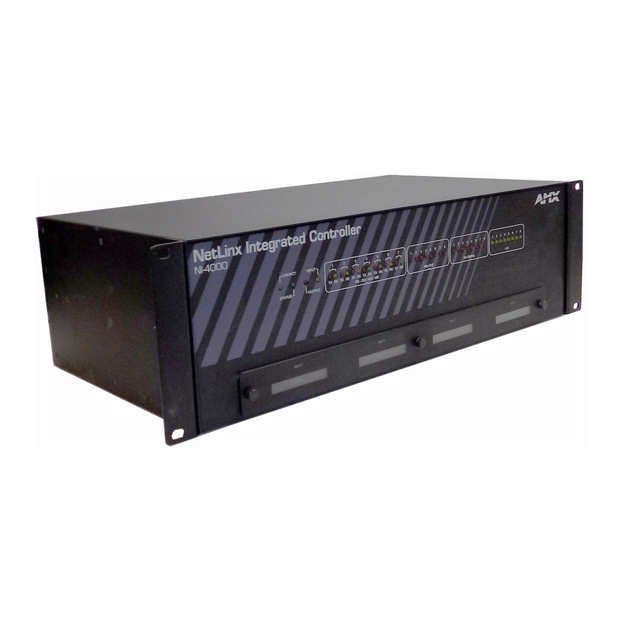
Introduction NI-3000 Specifications (Cont.) Optional Accessories: NI-4000 Specifications The front LEDs (FIG. 5) are grouped by control type, and are numbered according to their corresponding port (connector) numbers on the rear of the unit. The back of the this unit contains RS-232/422/485, Relay, IR/Serial and I/O connectors. - Page 17 Link/Active-Status-Output-Input NetLinx Card slots (1-4) Front Rear Relays (Port 8) CardFrame DIP switch FIG. 6 NI-4000 front and rear panel components NI-4000 Specifications Dimensions (HWD): Power requirements: Memory: Compact Flash: Weight: Enclosure: Front Panel Components: LINK/ACT Status Output Input RS-232/422/485 LEDs NetLinx Integrated Controllers RS-232/422/485 TX/RX LEDs (red/yellow) Relay LEDs (red)
- Page 18 Introduction NI-4000 Specifications (Cont.) Relay LEDs IR/Serial LEDs I/O LEDs NetLinx Control Card slots 1- 4 Rack-mount brackets Rear Panel Components: RS-232/422/485 (Ports 1 -7) ICSNet ICSHub Out Relay (Port 8) • Eight red LEDs light to indicate the rear relay channels 1-8 are active (closed) •...
- Page 19 NI-4000 Specifications (Cont.) Digital I/O (Port 17) IR/Serial (Ports 9-16) Program port Configuration DIP switch ID pushbutton Ethernet port Ethernet Link/Activity LED AXlink LED AXlink port Power port NetLinx Integrated Controllers • Eight-channel binary I/O port for contact closure • Each input is capable of voltage sensing. Input format is software selectable.
- Page 20 Introduction NI-4000 Specifications (Cont.) CardFrame Number DIP switch NetLinx Control Card connectors (1-4) Included Accessories: Optional Accessories: • Sets the starting address for the Control Cards in the CardFrame.(Factory default CardFrame DIP switch value = 0). • The Control Card address range is 1-3064. •...
-
Page 21: Quick Setup And Configuration Overview
Quick Setup and Configuration Overview Installation Procedures These are the steps involved with the most common installation procedures of these devices: Carefully unpack the contents of the box. Confirm the contents of box (page 2 thru page 14). Familiarize yourself with the units’ connectors and wiring configurations (Connections and Wiring section on page 17). -
Page 22: Update The Controller And Control Card Firmware
Quick Setup and Configuration Overview Update the Controller and Control Card Firmware Before using your new Integrated Controller, you must FIRST update your NetLinx Studio to the most recent release. Upgrade the on-board Master firmware through an IP Address via the Ethernet connector (Upgrading the On-board Master Firmware via an IP section on page 46) (IP recommended). -
Page 23: Connections And Wiring
Connections and Wiring Setting the Configuration DIP Switch (for the Program Port) Prior to installing the Controller, use the Configuration DIP switch to set the baud rate used by the Program port for communication. The Configuration DIP switch is located on the rear of the NI-4000/3000/2000 Integrated Controllers. -
Page 24: Using The Configuration Dip Switch
Connections and Wiring Think of the PRD Mode (On) equating to a PC’s SAFE Mode setting. This mode allows a user to continue powering a unit, update the firmware, and download a new program while circumventing any problems with a currently downloaded program. Power must be cycled to the unit after activating/deactivating this mode on the Program Port DIP switch #1. -
Page 25: Preparing Captive Wires
Preparing captive wires You will need a wire stripper and flat-blade screwdriver to prepare and connect the captive wires. Never pre-tin wires for compression-type connections. 1. Strip 0.25 inch (6.35 mm) of insulation off all wires. 2. Insert each wire into the appropriate opening on the connector (according to the wiring diagrams and connector types described in this section). -
Page 26: Using The 4-Pin Mini-Phoenix Connector For Data And Power
Connections and Wiring Using the 4-pin mini-Phoenix connector for data and power Connect the 4-pin 3.5 mm mini-Phoenix (female) captive-wire connector to an external NetLinx device as shown in FIG. 8. To the Integrated Controller’s AXlink/PWR connector Top view FIG. 8 Mini-Phoenix connector wiring diagram (direct data and power) Using the 4-pin mini-Phoenix connector for data with external power To use the NetLinx 4-pin 3.5 mm mini-Phoenix (female) captive-wire connector for data communication and power transfer, the incoming PWR and GND cable from the PSN must be... -
Page 27: Program Port Connections And Wiring
Program Port Connections and Wiring The Integrated Controllers are equipped with one Program port located on the rear of the unit. Use an RS232 programming cable to connect the Program port to your PC's COM port, this connection provides communication with the NetLinx Integrated Controller. Then you can download NetLinx programs to this on-board Master using the NetLinx Studio 2.2 software program. -
Page 28: Icsnet Rj-45 Connections/Wiring
Connections and Wiring RS-232/422/485 Device Port Wiring Specifications Pin Signal Function Receive data Receive data Transmit data Transmit data Signal ground Receive data Request to send Clear to send Transmit data ICSNet RJ-45 Connections/Wiring The following tables show the signal and pinouts/pairing information to use for ICSNet RJ-45 connections. -
Page 29: Icshub Out Port
The FIG. 11 illustrates the relative location of the ICSNet and ICSHub Out connectors on the rear panel. Ports FIG. 11 Location of ICSNet and ICSHub Out connectors Unlike the ICSNet ports, the ICSHub connections require a specific polarity. The IN/OUT configuration, on the hub ports, was implemented to use the same cables as ICSNet, but these ports need TX and RX crossed. -
Page 30: Ethernet Ports Used By The Integrated Controllers
Connections and Wiring RJ-45 plug FIG. 12 RJ-45 wiring diagram Ethernet LEDs L/A - Link/Activity LED lights (green) when the Ethernet cables are connected and terminated correctly. FIG. 13 Layout of Ethernet LEDs Ethernet ports used by the Integrated Controllers Ethernet Ports Used by the NetLinx Integrated Controllers Port type Description... -
Page 31: Relay Connections
A metal commoning strip is supplied with each Integrated Controller to connect multiple relays. Relay connections Use A for common and B for output (FIG. 14). Each relay is isolated and normally open. A metal connector strip is also provided to common multiple relays. RELAYS (Port 8) NI-4000/NI-3000 relay connector configuration (Port 8) -
Page 32: Ir/Serial Connections And Wiring
Connections and Wiring I/O Port Wiring Specifications NI-4000 and NI-3000 Signal I/O 1 I/O 2 I/O 3 I/O 4 I/O 5 I/O 6 I/O 7 I/O 8 12 VDC IR/Serial Connections and Wiring You can connect up to eight IR- or Serial-controllable devices to the IR/Serial connectors on the rear of the NI-4000 and NI-3000 and up to four on the NI-2000 (FIG. -
Page 33: Netlinx Control Card Slot Connector (Ni-4000 Unit Only)
Connections and Wiring NetLinx Control Card Slot Connector (NI-4000 unit only) FIG. 17 shows the 20-pin (male) connector that provides connection to the NetLinx Control Cards. SLOT 1 20 19 17 16 13 12 9 8 7 5 4 3 2 1 FIG. - Page 34 Connections and Wiring NetLinx Integrated Controllers...
-
Page 35: Installation And Upgrading
Installation and Upgrading Installing NetLinx Control Cards (NI-4000 Only) NetLinx Cards can be installed into the front card slots. The cards mount horizontally through the card slot openings on the front of the enclosure. To install a NetLinx Card: 1. Discharge the static electricity from your body, by touching a grounded object. 2. -
Page 36: Setting The Netlinx Control Card Addresses (Ni-4000 Only)
Installation and Upgrading If the cards do not appear in the Workspace window for the selected Master System number: give the system time to detect the inserted cards (and refresh the system) and/or cycle power to the NI-4000 unit. Setting the NetLinx Control Card Addresses (NI-4000 Only) The 8-position CardFrame Number DIP switch, located on the rear of the Integrated Controller, sets the starting address (the device number in the D:P:S specification) for the Control Cards installed in the CardFrame. -
Page 37: Removing Netlinx Control Cards (Ni-4000 Only)
Refer to the following accessing and installation sections for more information. The Compact Flash card is factory programmed with specific Controller firmware. These cards can be ordered from AMX in several different upgrade sizes (see the following table): Optional Compact Flash Upgrades Product Name... -
Page 38: Installation Of Compact Flash Upgrades
Installation and Upgrading Mounting Brackets Compact Flash Compact Flash insert location NXC Card Slot faceplate FIG. 20 Location of the Compact Flash within a sample Integrated Controller 3. Carefully pull-up and remove the housing up and away from the Controller to expose the internal circuit board (FIG. -
Page 39: Closing And Securing The Integrated Controller
6. Insert the upgrade card into the connector opening with the arrow facing towards the pins, then push it in firmly until the contact pins are completely inside the flash card and securely attached to the connector (FIG. 21). Under-side groove located below Insert with arrow facing towards... -
Page 40: Installing The Integrated Controller Into An Equipment Rack
Installation and Upgrading Installing the Integrated Controller into an Equipment Rack Use either the rack-mounting brackets (supplied with the NI-4000/3000/2000 controller) for equipment rack installations. Remove the mounting brackets for flat surface installations. Before completing the install process, it is recommended that you complete any firmware upgrade of the NetLinx Control Cards. - Page 41 7. Slide the unit into the rack until the attachment holes, along both sides, align to their corresponding locations on the mounting brackets, as shown in FIG. 22. 8. Secure the Rack Mount to the equipment rack by screwing in the four #10-32 screws (80-0186) and four #10 washers (80-0342) supplied in the Assembly Kit (KA2105-01) (in a clockwise direction).
- Page 42 Installation and Upgrading NetLinx Integrated Controllers...
-
Page 43: Configuration And Firmware Update
2. Verify you have installed the latest version of NetLinx Studio on your PC. 3. If an update is necessary, download the latest Studio software from www.amx.com > Tech Center > Downloadable Files > Application Files > NetLinx Studio 2.2. This program is used to setup a System number, obtain/assign the IP/URL for the connected NetLinx Master, and transfer firmware KIT files to the Master. -
Page 44: Setting The System Value
Configuration and Firmware Update FIG. 23 Assigning Communication Settings and Baud Rates 6. Click the Edit Settings button to open the Serial Settings dialog (FIG. 23). 7. Set the COM port parameters for the selected COM port used for communication to the NetLinx Master. -
Page 45: Using Multiple Netlinx Masters
This tab represents the only way to change the System Number associated to the active on-board NI Master. The Master must be rebooted to incorporate the new System number. 2. Select the Change System selection box from the System to Change section. 3. -
Page 46: Changing The Device Address On A Netlinx Device
Configuration and Firmware Update Changing the Device Address on a NetLinx Device 1. Access the Device Addressing dialog (FIG. 25) by either one of these two methods: Right-click on any system device listed in the OnLine Tree tab of the Workspace and select Device Addressing (from the pop-up list). -
Page 47: Recommended Netlinx Device Numbers
Recommended NetLinx Device numbers • 1 - 255 • 301 - 3072 • 5001 - 5999 • 6001 - 6999 • 7001 - 7999 • 8001 - 8999 • 10000 - 31999 • 33001 - 36863 • 32001 - 32767 •... -
Page 48: Obtaining The Master's Ip Address (Using Dhcp)
Configuration and Firmware Update Obtaining the Master’s IP Address (using DHCP) Verify there is an active Ethernet connection attached to the rear of the NI-Series Controller before beginning these procedures. 1. Select Diagnostics > Network Addresses from the Main menu to access the Network Addresses dialog. -
Page 49: Assigning A Static Ip To The Netlinx Master
8. Click OK to accept the new changes. 9. Click the Reboot Master button and select Yes to close the Network Address dialog. 10. Click Reboot (from the Tools > Reboot the Master Controller dialog) and wait for the System Master to reboot and retain the newly obtained DHCP Address. -
Page 50: Communicating With The On-Board Master Via An Ip
Network Addresses dialog to establish a new communication method to the Ethernet connected Integrated Controller. 1. Launch NetLinx Studio 2.2 (default location is Start > Programs > AMX Control Disc > NetLinx Studio > NetLinx Studio 2.2). - Page 51 FIG. 28 Assigning Communication Settings and TCP/IP Settings 7. Click the Edit Settings button (on the Communications Settings dialog) to open the TCP/IP Settings dialog (FIG. 28). 8. Enter the IP Address into the TCP/IP Address field. This information is obtained from either your System Administrator or from the Obtaining the Master’s IP Address (using DHCP) section on page 42.
-
Page 52: Verifying The Current Version Of Netlinx Master Firmware
Configuration and Firmware Update Verifying the current version of NetLinx Master Firmware All NI Integrated Controllers contain both an on-board Master and Controller. Each of these components has its own corresponding firmware. The on-board Master firmware KIT file is described as 2105_NI_Master and the Controller firmware KIT file is described as 2105_NI_X000. - Page 53 3. If the firmware version is not version 2 - build 135 or higher (ex: v2.XX.135), download the latest NI Master firmware file from www.amx.com > Tech Center > Downloadable Files > Firmware Files > NI Series. 4. Verify you have downloaded the latest NI Master firmware (KIT) file to a known location.
-
Page 54: Upgrading The Ni Controller Firmware Via An Ip
DHCP) section on page 42 to obtain the IP or Assigning a Static IP to the NetLinx Master section on page 43 to assign the address. 2. Launch NetLinx Studio 2.2 (default location is Start > Programs > AMX Control Disc > NetLinx Studio > NetLinx Studio 2.2). -
Page 55: Upgrading The New Ni Controller Firmware Via An Ip
8. Enter the IP Address into the TCP/IP Address field. This information is obtained from either your System Administrator or from the Obtaining the Master’s IP Address (using DHCP) section on page 42. 9. Click OK three times to close the open dialogs and save your settings. If you are currently connected to the assigned Master, a popup asks whether you would want to temporarily stop communication to the Master and apply the new settings. - Page 56 If the NI Integrated Controller firmware version is not version 1 - build 121 or higher (ex: v1.XX.121), download the latest NI Integrated Controller firmware file from www.amx.com > Tech Center > Downloadable Files > Firmware Files > NI Series. Then Download the 2105 NI_X000 KIT file to your Controller.
-
Page 57: Upgrading The Control Card Firmware Via An Ip
Workspace window. If the control card firmware is not up to date; download the latest firmware file from www.amx.com > Tech Center > Downloadable Files > Firmware Files > NXC-XXX. In this example, the NXC-VOL card contains out-of-date firmware and requires build 1.00.09. - Page 58 Configuration and Firmware Update FIG. 34 Select Control Card firmware file for download page (via IP) The OUTPUT and INPUT LEDs alternately blink to indicate the Master is incorporating the new firmware. Allow the Master 20 - 30 seconds to reboot and incorporate the new firmware.
-
Page 59: Netlinx Security And Web Server
This new build migrates the NetLinx Master security setup from a TELNET environment to a web-based application. The new NetLinx Web Server used to power the security and SSL certificate features on AMX Masters not only provides user name/password security for the target Master, but also a new level of secure encryption through the use of a unique server certificate. -
Page 60: New Master Firmware Security Features
NetLinx Security and Web Server When using Mozilla on a Linux machine, the Group Rights column checkboxes (from within the Modify User page) can become greyed-out but are actually present. New Master Firmware Security Features Master Security Telnet Security Terminal (RS232 Program port) security HTTP (Web Server) Security FTP Security SSL Certificate Encryption and Identification Technology... -
Page 61: Accessing The Netlinx Master Via Its Ip Address
Refer to the Upgrading the On-board Master Firmware via an IP section on page 46 for more detailed information on how to download the latest firmware (build 130 or greater) from www.amx.com. This firmware build enables SSL security and disables the ability to alter the Master security properties via a TELNET session. -
Page 62: Default Security Configuration
NetLinx Security and Web Server G3 panel pages accessed through the WebControl tab are virtual pages created by a user in TPDesign3 and then downloaded to the target Master. Interaction with these pages are not reflected on an actual G3 panel unless you use specific programming commands that link these virtual pages with their real G3 panel counterparts. -
Page 63: Security Tab
The NetLinx user account is created to be compatible with previous NetLinx Master firmware versions. This account is initially created by default and can later be deleted or modified. The administrator group account cannot be deleted or modified. The FTP Security and Admin Change Password Security are always enabled and cannot be disabled. -
Page 64: Security Tab - Enable Security Page
NetLinx Security and Web Server Security Tab Features (Cont.) SSL Certificate section Security tab - Enable Security page It is recommended that enabling the Master Security option be done after the groups, users, and passwords have been setup. If not, when the user accesses the Master from within another session, the default administrator user names and password are used for access. -
Page 65: Security Tab - Add Group Page
Security System Features (Cont.) OK/Cancel You must first enable the Master Security selection and then click OK before altering any settings. Click OK again after making alterations to any of these features (such as Terminal, HTTP, and Telnet access) and save these changes to the target Master. Security tab - Add Group page The Groups >... -
Page 66: Security Tab - Modify Group Page
NetLinx Security and Web Server Add Group Entries (Cont.) OK/Cancel A User represents a single potential client of the NetLinx Master, while a Group represents a logical collection of users. Any properties possessed by groups (example: access rights, directory associations, etc.) are inherited by all the members of the group. Security tab - Modify Group page The Groups >... -
Page 67: Security Tab - Group Directory Associations Page
Modify Group Entries (Cont.) HTTP Access Telnet Access Security Config Access OK/Cancel/Delete Security tab - Group Directory Associations page The Groups > Directory Associations link allows an authorized user to view current directory associations assigned to the selected group, add paths for new directory associations, and delete any previously configured directory associations (FIG. - Page 68 NetLinx Security and Web Server Here are some examples of valid entries: Valid Directory Association Entries Path /user1 /user1/ /Room1/iWebControlPages/* By default, all accounts that enable HTTP Access are given a '/*' Directory Association if no other Directory Association has been assigned to the account. Group Directory Association Entries Feature Select New Group...
-
Page 69: Security Tab - Add User Page
Security tab - Add User page The Users > Add User link allows an authorized user to add a user account (FIG. 40) and then assign that user’s current access rights. FIG. 40 Security Tab - Add User Add User Entries Feature User ID (user name) Group... -
Page 70: Security Tab - Modify User Page
NetLinx Security and Web Server Security tab - Modify User page The Users > Modify User link allows an authorized user to select from a listing of available users (FIG. 41) and then modify the Master’s access rights for the selected user. FIG. -
Page 71: Security Tab - User Directory Associations Page
Modify User Entries (Cont.) Telnet Access Security Config Access Password/Confirm OK/Cancel/Delete Security tab - User Directory Associations page The Users > Directory Associations link allows an authorized user to view current directory associations assigned to the selected user, add paths for new directory associations, and delete any previously configured directory associations (FIG. - Page 72 NetLinx Security and Web Server A single '/' is sufficient to grant access to all files and directories in the user directory and it's subdirectory. The '/*' wildcard can also be added to enable access to all files. All entries should start with a '/'.
-
Page 73: Security Tab - Ssl Server Certificate Page
Security tab - SSL Server Certificate page A certificate is a cryptographically signed object that associates a public key and an identity. Certificates also include other information in extensions such as permissions and comments. A "CA" is short for Certification Authority and is an internal entity or trusted third party that issues, signs, revokes, and manages these digital certificates. - Page 74 NetLinx Security and Web Server Server Certificate Entries (Cont.) City/Location State/Province Country Name Action OK/Cancel/Delete If a certificate has been purchased from an external CA and then installed onto a specific Master, DO NOT regenerate the certificate or alter its properties (ex: bit length, city, etc.).
-
Page 75: Security Tab - Export Certificate Request Page
Security tab - Export Certificate Request page The SSL > Export Certificate Request link opens an Export Certificate Request field (FIG. 44) where an authorized user can copy the raw text from a generated Certificate request into their clipboard and then send it to the CA. FIG. -
Page 76: System Tab
NetLinx Security and Web Server System Tab Displays the firmware version and log information for the NetLinx Master (FIG. 46). FIG. 46 System Tab Show Devices Tab Displays the device values and firmware versions of devices connected to the current NetLinx Master System (FIG. -
Page 77: Master Security Setup Procedures
Master Security Setup Procedures Setting the system security options for a NetLinx Master (Security Options Menu) 1. Enter the URL/IP Address of the target Master into the Address/URL field within the web browser. Refer to the Accessing the NetLinx Master via its IP Address section on page 55 for more detailed instructions on using your web browser to access your Master. -
Page 78: Adding A Group And Assigning Their Access Rights
NetLinx Security and Web Server 6. Click on the checkbox next to SSL Enable to enable the use of SSL encryption and server certificate usage. Activating this feature requires the creation of a server certificate. Refer to the SSL Certificate Procedures section on page 81 for instructions on creating and requesting a server certificate for the target Master. -
Page 79: Modifying An Existing Group's Access Rights
4. Click on the checkbox next to the requested access rights desired for the selected group. Placing a check in these fields activates the access rights (Terminal/Admin Change/FTP/ HTTP/Telnet/Security Configuration). Refer to the Security tab - Add Group page section on page 59 for more detailed field descriptions. -
Page 80: Showing A List Of Authorized Groups
NetLinx Security and Web Server 5. Click OK to accept and save the changes made on this tab to the Master. Clicking Delete removes the selected group from the list of authorized groups on the Master. Clicking Cancel voids any changes made within this tab, disables the security configuration session, voids any changes made to the Master, and returns you to the empty Security tab. -
Page 81: Adding A Group Directory Association
Adding a Group directory association 1. Click on the Security tab. By default this tab is blank until a security option is selected from the left of the browser window. Refer to the Security tab - Group Directory Associations page section on page 61 for more detailed descriptions on the security configuration options. 2. -
Page 82: Confirming The New Directory Association
NetLinx Security and Web Server Not only can an administrator provide group access to a file or folder on the Master, but also to an Application tab displayed within the web browser (such as Show Devices or Network). To add an association to an Application tab, enter the association location (ex: /showdevices.asp) into the Adding Association field. -
Page 83: Adding A User And Configuring Their Access Rights
Adding a User and configuring their access rights 1. Click on the Security tab. By default this tab is blank until a security option is selected from the left of the browser window. Refer to the Security tab - Add User page section on page 63 for more detailed descriptions on the security configuration options. -
Page 84: Modifying An Existing User's Access Rights
NetLinx Security and Web Server Each selection simply toggles the security setting from enabled to disabled. Modifying an existing User’s access rights 1. Click on the Security tab. By default this tab is blank until a security option is selected from the left of the browser window. -
Page 85: Showing A List Of Authorized Users
6. Enter the same password for the user into both the Password and Confirm fields if you want to change the password. Leaving this field blank retains the current or previous password. A user password is a valid character string (4 - 20 alpha-numeric characters) that is used to supplement the user name/ID in defining the potential client. -
Page 86: Adding A User Directory Association
NetLinx Security and Web Server Adding a User directory association 1. Click on the Security tab. By default this tab is blank until a security option is selected from the left of the browser window. Refer to the Security tab - User Directory Associations page section on page 65 for more detailed descriptions on the security configuration options. -
Page 87: Confirming The New Directory Association
Confirming the new directory association 1. Click on the Security tab. 2. Click the Directory Associations link. 3. From the Delete Association section of the User Directory Associations window, click the down arrow from the Select Association field to open a list of associations and confirm the new directory association has been assigned to the user. -
Page 88: Self-Generating A Ssl Server Certificate Request
NetLinx Security and Web Server Self-Generating a SSL Server Certificate Request 1. Click on the Security tab (FIG. 55). Refer to the Security tab - SSL Server Certificate page section on page 67 for more detailed descriptions on the security configuration options. 2. -
Page 89: Creating A Request For A Ssl Server Certificate
11. Choose Self Generate Certificate from the drop-down list. certificate is generated and installed into the Master in one step. 12. Click OK to save the new encrypted certificate information to the Master or click Cancel to void any changes made within this tab and exit without making changes to the target Master. ONLY use the Regenerate certificate option when you have Self Generated your own certificate. -
Page 90: Importing A Ca Certificate To The Master Over A Secure Ssl Connection
NetLinx Security and Web Server 10. Click the down arrow from the Action field to open a drop-down listing of available certificate generation options. 11. Choose Create Request from the drop-down list. 12. Click OK to accept the information entered into the above fields and generate a certificate file. Refer to the Security tab - Export Certificate Request page section on page 69. -
Page 91: Display Ssl Server Certificate Information
4. Click OK to enter the new encrypted certificate information and save it to the Master or click Cancel to void any changes made within this tab and exit without making changes to the target Master. Once a certificate has been purchased from an external CA and then installed onto a specific Master, DO NOT regenerate the certificate or alter its properties (example: bit length, city, etc.).If the purchased certificate is regenerated, it becomes invalid. -
Page 92: Common Steps For Requesting A Certificate From A Ca
NetLinx Security and Web Server This method of certificate generation is used to modify or recreate a previously existing certificate already on the Master. By default, if a certificate is already present on the target Master, the Display Certificate Action is selected and these fields are populated with information. Ex: if the company has moved from Dallas to Houston, all of the information is reentered exactly except for the City. - Page 93 4. Enter the name of the server being used (this is the Master). The server name is the name as it shows up in the URL of the Master you are securing with this server certificate. For example, if the URL of the Master will be https://www.myNetLinxMaster.com/, then enter the server name as www.myNetLinx Master.com.
-
Page 94: Accessing An Ssl-Enabled Master Via An Ip Address
NetLinx Security and Web Server Accessing an SSL-Enabled Master via an IP Address 1. Enter the IP Address of the target Master (example: 198.198.99.99) into the web browser Address field. 2. Press the Enter key on your keyboard to begin the communication process between the target Master and your computer. - Page 95 6. The user is then presented with a Certificate Import Wizard that begins the process of adding the certificate (FIG. 57). FIG. 57 Certificate Import Wizard 7. Click Next to proceed with the certificate storage process. FIG. 58 Certificate Import Wizard- storing the certificate 8.
-
Page 96: Using Your Netlinx Master To Control The G4 Panel
NetLinx Security and Web Server 18. The first tab displayed within your open browser window is WebControl. Using your NetLinx Master to control the G4 panel Refer to the specific panel instruction manual for detailed information on configuring and enabling WebControl. -
Page 97: Using Your Netlinx Master To Control The G3 Panel
FIG. 60 WebControl VNC installation and Password entry screens 8. Click Yes from the Security Alert popup window to agree to the installation of the G4 WebControl application on your computer. This application contains the necessary Active X and VNC client applications necessary to properly view and control the panel pages from your computer. -
Page 98: What To Do When A Certificate Expires
NetLinx Security and Web Server 3. Restart your computer and launch your browser. 4. Repeat steps 1 - 5 from the previous section to launch the WebControl tab associated with your Master. 5. Click on the G3 panel name link associated with the target panel. 6. -
Page 99: Netlinx Security With A Terminal Connection
NetLinx Security with a Terminal Connection NetLinx Masters (version 2.10.80 or later) have built-in security capabilities. It will require a valid user name and password to access the NetLinx System’s Telnet, HTTP and FTP servers. The security capabilities are configured and applied via a Telnet connection or the NetLinx Master’s RS-232 terminal interface (the RS232 Program port). -
Page 100: Accessing The Security Configuration Options
NetLinx Security with a Terminal Connection 4. Enter any text into the Name field of the HyperTerminal Connection Description dialog window and click OK when done. 5. From the Connect Using field, click the down-arrow and select the COM port being used for communication by the target Master. -
Page 101: Option 1 - Set System Security Options For Netlinx Master (Security Options Menu)
Option 1 - Set system security options for NetLinx Master (Security Options Menu) Type 1 and <ENTER> display the Security Options Menu. The Security Options Menu sets the "global" options for the NetLinx Master. It is accessed by the Set Security system options of the Main Security Menu. This first thing that will happen is you will be asked one of two questions. -
Page 102: Option 2 - Display System Security Options For Netlinx Master
NetLinx Security with a Terminal Connection Changes made to the target Master from within the Terminal window are not reflected within the web browser, until the Master is rebooted and the web browser connection is refreshed. Any changes made to the Master, from within the web browser are instantly reflected within the Terminal session without the need to reboot. -
Page 103: Option 4 - Edit User
4. Enter a password for the new user. A password is a valid character string (4 - 20 alpha-numeric characters) to supplement the user name in defining the potential client. This string is also case sensitive. 5. The session then prompts you to verify the new password. Enter the password again, and press <ENTER>... - Page 104 NetLinx Security with a Terminal Connection The Edit User Menu options are described in the following table: Edit User Menu Command 1) Change User Password 2) Change Inherits From Group 3) Add Directory Association 4) Delete Directory Association This selection will display any current Directory Associations 5) List Directory Associations This selection will display any current Directory Associations 6) Change Access Rights 7) Display User Record Contents This selection will display the group the user is assigned to and the...
-
Page 105: Option 5 - Delete User
Access Rights Menu Command 1) Terminal (RS232) Access (Enable/Disable) 2) Admin Change Password Access (Enable/Disable) 3) FTP Access (Enable/Disable) 4) HTTP Access (Enable/Disable) 5) Telnet Access (Enable/Disable) 6) Security Configuration Access (Enable/Disable) Option 5 - Delete user 1. Type <ENTER> to delete an existing user account. - Page 106 NetLinx Security with a Terminal Connection 2. Enter a name for the group. A group name is a valid character string (4 - 20 alpha-numeric characters) defining the group. This string is case sensitive, and each group name must be unique.
- Page 107 access to a file or directory. From the answer, it will enter the appropriate Directory Association. The NetLinx Master will not create the path if it is not valid. That must be done via another means, most commonly by using an FTP client and connecting to the FTP server on the NetLinx Master.
-
Page 108: Option 8 - Edit Group
NetLinx Security with a Terminal Connection Edit Group menu: Display Access Rights 1. At the Edit Group prompt, type 5 to view the current access rights for the selected group account. A sample session response is: Terminal (RS232)...Disabled Admin Password Change...Disabled FTP...Disabled HTTP...Disabled Telnet...Disabled... -
Page 109: Option 10 - Show List Of Authorized Groups
Option 10 - Show List of Authorized Groups 1. Type 10 and <ENTER> at the Security Setup prompt (at the bottom of the Main Security Menu) to display a list of all authorized group accounts. A sample session response is: The following groups are currently enrolled: administrator Group 1... -
Page 110: Main Security Menu
NetLinx Security with a Terminal Connection Main Security Menu The Main Security menu is described below: Main Security Menu Command 1) Set system security options for NetLinx Master 2) Display system security options for NetLinx Master 3) Add user 4) Edit user 5) Delete user 6) Show the list of authorized users 7) Add group... -
Page 111: Default Security Configuration
Main Security Menu (Cont.) Command 13) Make changes permanent by saving to flash 14) Reset Database 15) Display Database Default Security Configuration By default, the NetLinx Master will create the following accounts, access rights, directory associations, and security options. Account 1: Password: Group: Rights:... -
Page 112: Help Menu
NetLinx Security with a Terminal Connection Help menu Type help at the prompt in the Telnet session to display the following help topics: Help Menu Options Command ----- Help ----- <D:P:S> ? or Help DATE DEVICE HOLDOFF ON|OFF DEVICE STATUS <D:P:S> DNS LIST <D:P:S>... -
Page 113: Logging Into A Session
ENABLE:DISABLED Logging Into a Session Until Telnet security is enabled, a session will begin with a welcome banner. Welcome to NetLinx v2.10.80 Copyright AMX Corp. 1999-2004 > The welcome banner is not displayed for Terminal sessions. When Terminal security is enabled, the user will be prompted for a user name and password before they will be allowed to access any commands available from Telnet. -
Page 114: Logout
After the password is entered, if the password is correct you will see a welcome banner as shown below: Login: User1 Password: ***** Welcome to NetLinx v2.10.80 Copyright AMX Corp. 1999-2002 > If the password is incorrect, the following will be displayed: Login: User1 Password: ***** Login not authorized. -
Page 115: Programming
For more information on NetLinx standards and conversion recommendations, go to www.amx.com and click on Dealers > Tech Center > Tech Notes. You can either search for the documents (such as NetLinx Programming Standards and Converting Axcess Code to NetLinx Code) or Tech Notes (TN numbers: 186, 249, 261, and 310). -
Page 116: Program Port Commands
Programming For example: STRUCTURE DEV INTEGER Number INTEGER Port INTEGER System The D:P:S notation is used to explicitly represent a device number, port and system. For example, 128:1:0 represents the first port on device 128 on this system. If the system and Port specifications are omitted, (e.g. - Page 117 Program Port Commands (Cont.) GET IP <D:P:S> MSG OFF MSG ON PASS PING PROGRAM INFO PULSE REBOOT <D:P:S> RELEASE DHCP SEND_COMMAND SEND_STRING SET DATE SET DNS <D:P:S> NetLinx Integrated Controllers Displays the Master Card's D:P:S, Host Name, Type (DHCP or Static), IP Address, Subnet Mask, Gateway IP, and MAC Address.
- Page 118 Programming Program Port Commands (Cont.) SET IP <D:P:S> SET TIME SET URL <D:P:S> SHOW DEVICE <D:P:S> SHOW LOG SHOW NOTIFY SHOW REMOTE SHOW ROUTE SHOW SYSTEM TCP LIST TIME URL LIST <D:P:S> Prompts you to enter a Host Name, Type (DHCP or Fixed), IP address, Subnet Mask, and Gateway IP address.
-
Page 119: Esc Pass Codes
ESC Pass Codes There are 'escape' codes in the pass mode. These codes can switch the display mode or exit pass mode. The following 'escape' codes are defined. Escape Pass Codes Command + + ESC ESC + + ESC A + + ESC D + + ESC H Notes on Specific Telnet/Terminal Clients... -
Page 120: Linux Telnet Client
Programming Linux Telnet client The Linux Telnet client has three anomalies that are known at this time: A null (\00) character is sent after a carriage return. If an ALT 255 is entered, two 255 characters are sent (per the Telnet RAFT). If the code to go back to command mode is entered (ALT 29 which is ^]), the character is not sent, but Telnet command mode is entered. - Page 121 RS-232/422/485 Send_Commands (Cont.) B9MON Overrides and sets the communication settings on the RS-232 port to nine data bits and one stop bit. CHARD Sets the delay time between transmitted characters in 100 microsecond increments. CHARDM Sets the delay time between transmitted characters in 1 millisecond increments.
- Page 122 Programming RS-232/422/485 Send_Commands (Cont.) HSON Enables RTS (ready-to-send) and CTS (clear-to-send) hardware handshaking. RXCLR Clears all characters in the receive buffer waiting to be sent to the Master Card. RXOFF Stops transmitting received characters to the Master Card (default). RXON Starts transmitting received characters to the Master Card.
-
Page 123: Rs-232/422/485 Send_String Escape Sequences
RS-232/422/485 Send_Commands (Cont.) TXCLR Stops and clears all characters waiting in the transmit buffer. XOFF Disables software handshaking (default). Enables software handshaking. RS-232/422/485 Send_String Escape Sequences RS-232/422/485 Send_String Escape Sequences 27,17, Sends device-specific break characters for a specified duration. 27,18,1 Sets the ninth data bit to 1 on all character transmissions. -
Page 124: Ir / Serial Ports Channels
Programming RS-232/422/485 Send_String Escape Sequences (Cont.) 27,20,0 Sets the RTS hardware handshake's output to high. 27,20,1 Sets the RTS hardware handshake's output to low. IR / Serial Ports Channels IR / Serial Ports Channels 00001 - 00229 IR commands. 00229 - 00253 May be used for system call feedback. 00254 Power Fail. - Page 125 IR/Serial Send_Commands (Cont.) Sends IR pulses to select a channel. All channels below 100 are transmitted as two digits. If the IR code for ENTER (#21) is loaded, an Enter will follow the number. If the channel is greater than or equal to 100, the IR function 127 is generated for the one hundred digit.
- Page 126 Programming IR/Serial Send_Commands (Cont.) GET MODE Polls the IR/Serial ports and reports the active mode settings to the device requesting the information. IROFF Halts and clears all IR output on the designated port. Disables active PON (power on) or POF (power off) command settings.
- Page 127 IR/Serial Send_Commands (Cont.) PTOF Sets the time between power pulses in .10-second increments, and is stored in permanent memory. PTON Sets the duration of power pulses in .10-second increments. Time is stored in permanent memory. SET IO LINK Links an IR or Serial port to an I/O channel for use with DE, POD, PON and POF commands.
- Page 128 Programming IR/Serial Send_Commands (Cont.) XCHM Changes the IR output pattern for the XCH command. Syntax: SEND_COMMAND <DEV>,'XCHM-<Mode>' Variable: Mode = 0-4 Example: SEND_COMMAND IR_1,'XCHM 3' Sets the IR_1 device's extended channel command to mode 3. Mode 0 Example (default): [x] [x] <x> <enter> SEND_COMMAND IR_1, 'XCH 3' Transmits the IR code as 3-enter.
-
Page 129: Input/Output Send_Commands
Input/Output Send_Commands The following Send_Commands program the I/O ports on the Integrated Controller. I/O SEND_COMMANDS GET INPUT Gets the input channels active state. SET INPUT Sets the input channel's active state. NetLinx Integrated Controllers An active state can be high (logic high) or low (logic low or contact closure). Channel changes, Pushes, and Releases generate reports based on their active state. - Page 130 Programming NetLinx Integrated Controllers...
-
Page 131: Troubleshooting
Troubleshooting This section describes the solutions to possible hardware/firmware issues that could arise during the common operation of a Modero touch panel. Troubleshooting Information Symptom My NI Controller can’t obtain a DHCP Address. My NI Controller shows the same IP Address after selecting DHCP Server and clicking the GET IP Information button. - Page 132 Troubleshooting Troubleshooting Information (Cont.) Symptom I can’t connect to my NI Controller via the rear Program Port using a DB9 cable. My NetLinx devices drop offline periodically when communicating over Ethernet. When plugging the Master into a fixed speed hub or switch; (i.e.
- Page 133 Troubleshooting Information (Cont.) Symptom During the firmware upgrade process, NetLinx Studio failed to install the last component. NetLinx Integrated Controllers Solution This occurs when initially upgrading the on-board Master from a previous firmware (build 117 or lower), to the new Web Security firmware (build 130 or higher).
- Page 134 ATLANTA • BOSTON • CHICAGO • CLEVELAND • DALLAS • DENVER • INDIANAPOLIS • LOS ANGELES • MINNEAPOLIS • PHILADELPHIA • PHOENIX • PORTLAND • SPOKANE • TAMPA 3000 RESEARCH DRIVE, RICHARDSON, TX 75082 USA • 800.222.0193 • 469.624.8000 • 469-624-7153 fax • 800.932.6993 technical support • www.amx.com...