
Related Manuals for Meyra X1


Summary of Contents for Meyra X1
-
Page 1: Folding Wheelchair
OPERATING MANUAL FOLDING WHEELCHAIR X1 model 3.350 X2 model 3.351 X3 model 3.352 We move people. -
Page 2: Table Of Contents
Table of contents Introduction Acceptance Assembly Specifications / utilisation Driving behaviour Overview Brake Pressure brake Service brake Locking the pressure brakes Releasing the pressure brakes Adjusting the pressure brakes Leg strap Leg supports Folding up the footboard Folding up the footboard Folding up the footboard (Code 313) Folding down the footboard Folding down the footboard (Code 313) - Page 3 Remove the leg supports Attaching the legrests Altering the footboard height Depth adjustable footplates Clothes guard Height adjustable arm supports Wheels Drive wheels Quick release axle Handrims Vario block Centre of gravity Wheel camber Variable seat height Steering wheels Tyres Support wheels Seatbelt Back support with angle adjustment...
- Page 4 Tyre change of the drive wheels Tyre change of the steering wheels Repair Spare parts Disposal Disinfection Reinstallment Technical data X1, model 3.350 X2, model 3.351; X2, model 3.351-351 X3, model 3.352 Stickers on the wheelchair Inspection certificate Notes Guarantee Guarantee coupon...
-
Page 5: Introduction
☞ Note: way of a new styling of the proven MEYRA However, we request that you check the technology. Benefit from the design advantag- vehicle for possible transport damage im- es of your wheelchair, both indoors (e.g. -
Page 6: Specifications / Utilisation
SPECIFICATIONS/ UTILISA- DRIVING TION The first adjustment of the driving features of your wheelchair to suit your personal needs The wheelchair is designed for universal use will be possible at once, following a brief “in- and therefore all-round wheelchair for indoor troductory “... -
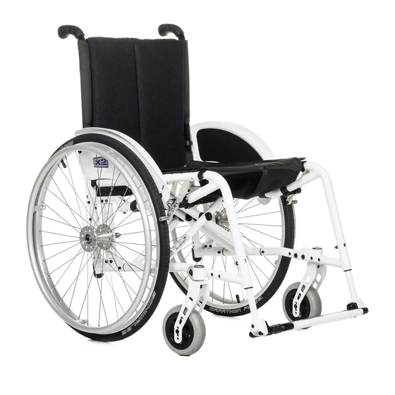
Page 7: Overview
OVERVIEW Model 3.350-X1 / 3.351-X2 The model shown in fig. 1 is the standard version. All deviations are specified separately in this operating manual. Fig. 1 Pos. Description 1 Push handle 7 Steering wheel 8 Drive wheel 2 Back support... - Page 8 OVERVIEW Model 3.352-X3 The model shown in fig. 1a is the standard version. All deviations are specified separately in this operating manual. Fig. 1a Pos. Description 1 Push handle 8 Footboard/footplates divided 9 Steering wheel 2 Back support 3 Height adjustable armrest 10 Support wheel 4 Mudguard 11 Locking knob / linchpin...
-
Page 9: Brake
BRAKE The wheelchair is fitted with a pressure brake (fig. 2). It works directly on the tyres. Pushing the brake levers to the end stop locks the brakes and prevents your wheelchair from being pushed (parking brakes). Benefits: – Controlled braking of the driving speed (service brake). -
Page 10: Adjusting The Pressure Brakes
Adjusting the pressure brakes The pressure brakes must be readjusted after each refitting of a drive wheel. Pre-setting of the pressure brakes: – Loosen the clamping screws (1, fig. 4) of one pressure brake. – Pre-set the pressure brake – Slide the brake bolt of the non-activated pressure brake to a point approx. -
Page 11: Leg Strap
CALF BELT The leg strap (6) prevents the feet from slipping from the foot board. It is lead around the front frame tubes (fig. 5) and adapted to the correct length with the velcro strap. Attention: Never drive without leg strap (except when shuffling)! LEG SUPPORTS FOLDING UP THE FOOTBOARD... -
Page 12: Folding Down The Footboard
Folding down the foot board Fold down the left side of the foot board until it rests on the foot board holder (fig. 7). Folding down the foot board (Code 313) Fold down the right side of the foot board until it rests on the foot board holder (fig. -
Page 13: Leg Supports, Model 3.351
LEG SUPPORTS, MODEL 3.351 Code 808/663 Folding up the footplates Benefits: – Easy transfer into and out of the wheelchair. – Leg region free, no stumbling. – “shuffling” possible (moving the wheelchair forward with the feet). Handling: – Operate parking brakes. – This prevents the wheelchair from rolling away accidentally. -
Page 14: Angle Adjustment Of The Footplates
Angle adjustment of the footplates The footplates can be angle adjusted by max. +/– 10° in 5 steps of 5° each. Handling: – Operate parking brakes. – This prevents the wheelchair from rolling away accidentally. – Screw out the screws (A, fig. 13) about 2- 3mm. -
Page 15: Folding Down The Footplates
Folding down the footplates Handling: – Operate parking brakes. – This prevents the wheelchair from rolling away accidentally. – Successively fold the footplates, according to the connection elements inward and down. – In doing so the groove joint of the footplates must form coherently lock into place (fig. -
Page 16: Swivelling Away The Leg Supports
Turning the leg supports to the side Handling: – Operate parking brakes. – This prevents the wheelchair from rolling away accidentally. – Remove both feet from the footplates – Successively fold the footplates outward and up (fig. 13.4). – To swivel away the leg supports, press the respective locking bracket forward against the frame tube (fig. -
Page 17: Remove The Leg Supports
Remove the leg supports – Press the locking bracket forward against the frame tube (fig. 13.5). Afterwards re- move the leg support toward the top. Attaching the leg supports – Hang the leg support from the top onto the upper and lower leg support pin (A, fig. 13.7) and swivel it inwards again. -
Page 18: Clothes Guard
CLOTHES GUARD Code 101 Benefits: – Lateral support for body. – Protection against mud from the tyres. – Wind protection. The mudguard (fig. 14) running parallel to the circumference of the wheel has to be adjusted to the selected wheel position and size. Attention: Do not lift your wheelchair via the clothing guards! -
Page 19: Height Adjustable Arm Supports
HEIGHT ADJUSTABLE ARM SUPPORTS Code 81, code 748, code 749 (Model 3.351 / 3.352) The arm support is height adjustable in 5 posi- tions of 15 mm each. Attention: Before loosening the screws hold on to the arm support to prevent it from unintentional lowering. -
Page 20: Height Adjustment
Code 81, code 84 Removing the arm support – Press in the locking lever in front of the plas- tic side wall (A, fig. 17.1). – swivel the arm support up first, then remove it toward the top. Attaching the arm support –... -
Page 21: Wheels
WHEELS DRIVE WHEELS ☞ Note: You will find the air pressure values for the tyres for your wheelchair in the Technical Specifications or the information given for both sides of the wheels. QUICK RELEASE AXLE The driving wheels can be removed and reas- sembled without any tools. -
Page 22: Vario Block
VARIO BLOCK Benefits: – Individual adaptation of the seat height to your lower leg length. – Higher sitting stability as well as a better dis- tribution of the sitting pressure through ad- justable seat angle. – Increased tilting stability through change of wheelbase. -
Page 23: Variable Seat Height
Variable seat height By repositioning the axle adapter (B, fig. 21.1) together with a new steering wheel ad- justment the seat height and tilt is adjustable. ☞ Important information: Attachment screws to adjust the castor stem (D, fig. 21.2) have to be secured with soluble Loctite glue after every third adjustment. -
Page 24: Steering Wheels
STEERING WHEELS The steering wheels (8) can be exchanged without difficulty. Handling: ☞ Note: Take note of the arrangement of all sleeves and washers used. – Dismantle steering wheel screw connection (A, fig. 22). – Replace steering wheel, if necessary or reposition to suit your requirements. -
Page 25: Support Wheels
SUPPORT CASTORS The support wheels are to increase the tilting stability (fig. 26) and can be swivelled under the seat (fig. 28). – Higher tilting stability through the support wheels. – Free foot space for the helper with the sup- port wheels swung inwards. -
Page 26: Angle Adjustment
SUPPORT CASTORS Angle adjustment The support wheels are angle adjustable in three positions in case a height adjustment does not achieve the ideal position of the sup- port wheels. Handling: – Remove screw (B, fig. 30). – Slightly loosen screw (C, fig. 30). –... -
Page 27: Seatbelt
SEAT BELT Code 833 The seatbelt serves to strap in a person sitting in the wheelchair. Benefits: – Additional stabilisation of the sitting posi- tion. – Prevents user from falling forward out of the wheelchair (depending on degree of disa- bility). - Page 28 Belt adjustment: – Hold latch mechanism at a right-angle to the belt. – Pull the belt in the relevant direction for lengthening or shortening. – Secure excess belt material by moving the plastic slide. ☞ Note: The seatbelt should be pulled taught, but not too tight.
-
Page 29: Back Support With Angle Adjustment
BACK SUPPORT WITH AN- GLE ADJUSTMENT Code 31 The back support is adjustable by max. +/– 15° in three steps of 5° each. Handling: – Loosen the screws (A, fig. 33) on both sides, adjust the back support to the desired angle. -
Page 30: Height Adjustable Push Handles
HEIGHT ADJUSTABLE PUSH HANDLES Code 140 The push handles are steplessly height adjusta- ble by max. 12 cm (fig. 34). Handling: – Pull the clamping lever (B, fig. 35) upward and adjust the push handle to the desired height. – After the adjustment push the clamping lever down again. -
Page 31: Folding/Unfolding
FOLDING/UNFOLDING Your wheelchair can be folded in a few mo- ments without tools being required (fig. 36). The new crossbrace design results in a small folded size and ensures a high wheelchair sta- bility after unfolding. Benefits: – Easy to fold without any tools. –... -
Page 32: Loading And Transportation
LOADING AND TRANS- Carry out the following steps when the wheel- PORTATION chair is located in the transport vehicle: – Operate parking brakes. CARRYING THE WHEELCHAIR – Any parts that have been dismantled from the wheelchair should be stored safely in a Your wheelchair can be carried without diffi- protected place. -
Page 33: Transport In Handicapped Transport Automobile
TRANSPORT IN HANDI- The power-knot-system is a firm, retrofittable element on the wheelchair, on which the PRS CAPPED TRANSPORT AU- and WRS merge. TOMOBILE These requirements are fulfilled by a 4-point- ☞ Note: system that consists of 2 front standardised For transport in vehicles we recommend to latches for spanning reactor and 2 rear stand- leave the wheelchair and sit on a suitable... -
Page 34: Product Liability Instructions
☞ Note: SAFETY INFORMATION The headrest on the wheelchair serves as ☞ When transporting a person, make sure a support for the posture of the head, not that there are no objects jammed under- as a transport security. Therefore a handi- neath the straps! –... -
Page 35: Maintenance
SERVICE Finish: The high quality finish ensures an optimum of protection against corrosion. Should the coat- CARE ing be damaged through scratches or similar, repair the spot with a varnish pen that you can Seat and back support cover: obtain from us. Occasional application of a Clean the covers with warm water. -
Page 36: Maintenance
MAINTENANCE/SERVICING Like any other technical product, your wheel- chair also requires maintenance. The follow- ing maintenance instructions describe in table form the measures necessary in order for you to continue enjoying the benefits of your wheelchair (e.g. easy folding, little rolling re- sistance) to the full, even after a long period of use. -
Page 37: Maintenance Instructions
MAINTENANCE INSTRUCTIONS WHEN WHAT REMARK Before starting Test brakes for faultless If they can still turn, the operation brakes must be repaired by a specialist workshop. Activate brake lever (5) to the lim- it. The locked wheels should not be able to turn under operating conditions. - Page 38 MAINTENANCE INSTRUCTIONS WHEN WHAT REMARK Before starting Check air pressure of the Do it yourself or with the aid tyres of a helper. Use a tyre pressure tester or, Standard tyres: if not available, the ‘thumb 4 bar = 56 psi press’...
- Page 39 MAINTENANCE INSTRUCTIONS WHEN WHAT REMARK Every 8 weeks Lubricate the following Do it yourself or with the aid components with a of a helper. (depending on frequency of few drops of oil Components must be free use) from used oil residues before –...
-
Page 40: Flat Tyre
FLAT TYRE If a flat tyre occurs to the air filled tyres due to puncture by sharp objects such as nails, screws, glass splinters, etc. the damage should be eliminated by repairing (mending the inner tube) or replacing the inner tube. Attention: Sitting in the wheelchair during a wheel change is not permitted. -
Page 41: Repair
REPAIR DISPOSAL For carrying out repairs contact a dealer. The vehicle packing material can be disposed of as recyclable material. SPARE PARTS The metal parts can be disposed of as recycla- Spare parts can only be ordered from special- ble scrap metal. ist dealers. -
Page 42: Technical Data
10%. If this is not possible, a more stable version or another wheelchair model must be used. Con- Temperature range: tact your MEYRA specialist dealer in this re- spect. Ambient temperature: - 20°C up to + 40°C... -
Page 43: X1, Model 3.350
X1, MODEL 3.350 All data within the following table relates to the standard version of the stated model. Dimensional tolerance ± 1.5 cm, +/-2°. Model: ................... X1, 3.350 Type plate: ..................at the crossbrace tube Dimensions (unless otherwise noted with 24“ drive wheels) Length: on standard frame: .................... - Page 44 Lower leg length (without seat cushion): with leg supports code 808: ..............38 up to 48 cm with leg supports code 54: ..............38 up to 48 cm with foot board code 54/123 (steplessly): ..........30 up to 38 cm Wheels Steering wheel: ø...
-
Page 45: X2, Model 3.351; X2, Model 3.351-351
X2, MODEL 3.351; X2, MODEL 3.351-351 All data within the following table relates to the standard version of the stated model. Dimensional tolerance ± 1.5 cm, +/-2°. Model: ..............X2, 3.351; X2, 3.351-351 Type plate: ..................at the crossbrace tube Dimensions (unless otherwise noted with 24“... - Page 46 Lower leg length (without seat cushion): with leg supports code 808/663: ............38 up to 48 cm Wheels Steering wheel: ø 100 mm: ....................puncture safe ø 125 mm: ....................puncture safe 6 x 1 ¼“: ....................puncture safe Driving wheel: 22“...
-
Page 47: X3, Model 3.352
X3, MODEL 3.352 All data within the following table relates to the standard version of the stated model. Dimensional tolerance ± 1.5 cm, +/-2°. Model: ................... X3, 3.352 Type plate: ..................at the crossbrace tube Dimensions (unless otherwise noted with 24“ drive wheels) Length: on standard frame: .................... - Page 48 Lower leg length (without seat cushion): with leg supports code 808: ..............38 up to 48 cm with leg supports code 54: ..............38 up to 48 cm with foot board code 54/123 (steplessly): ..........30 up to 38 cm Wheels Steering wheel: ø...
-
Page 49: Stickers On The Wheelchair
STICKERS ON THE WHEELCHAIR Attention! Read the operating manuals and other provid- ed documentation. Do not lift the wheelchair at the arm supports or leg supports. Detachable parts are not suitable for carrying. -
Page 50: Inspection Certificate
INSPECTION CERTIFICATE Vehicle data: Model: Delivery note no.: Vehicle identification No. Recommended safety inspection Pre-delivery inspection (at least every 12 months) etailer stamp:: etailer stamp: Signature: Signature: Place, date: Place, date: Next safety inspection in 12 months Next safety inspection in 12 months Date: Date: Recommended safety inspection... - Page 51 Recommended safety inspection Recommended safety inspection (at least every 12 months) (at least every 12 months) etailer stamp: etailer stamp: Signature: Signature: Place, date: Place, date: Next safety inspection in 12 months Next safety inspection in 12 months Date: Date: Recommended safety inspection Recommended safety inspection (at least every 12 months)
-
Page 52: Notes
NOTES... - Page 53 NOTES...
-
Page 54: Guarantee
GUARANTEE Guaranty is not granted for surface damages, tyres of the wheels, damages due to loosened screws or nuts as well as worn out attachment We accept a guaranty for this product accord- holes due to frequent assembly work. ing to the legal regulations. Apart from this we warrant: Furthermore, damages to the product caused by improper cleaning using steam cleaning... -
Page 55: Guarantee Coupon
GUARANTEE NOTE Fill in the details! If necessary, copy and return. Guarantee Model designation: Delivery note no.: Vehicle ID No. (Fz-I-Nr.) (view type plate): Date of delivery: Stamp of the authorised dealer:... - Page 56 Your specialist dealer: MEYRA-ORTOPEDIA Vertriebsgesellschaft mbH Meyra-Ring 2 · D-32689 Kalletal-Kalldorf P.O. Box 1 703 • D-32591 Vlotho Fon +49 (0)5733 922-355 Fax +49 (0)5733 922-9355 info@meyra.de · www.meyra.de We move people. info@ortopedia.de · www.ortopedia.de 205 999 201 (Status: 2006-05) All technical modifi cations reserved!