Table of Contents
Advertisement
Quick Links
Advertisement
Table of Contents

Related Manuals for Meyra BRIX 1.123


Summary of Contents for Meyra BRIX 1.123
- Page 1 The Motivation. CHILDREN’S WHEELCHAIRS BRIX Model 1.123 OPERATING MANUAL...
-
Page 3: Table Of Contents
Table of contents Introduction ....................6 Acceptance ....................6 Assembly ....................7 Specifications/ utilisation ................ 7 Overview ....................8 Driving behavior ..................9 Safety informations ..................9 Supplementary user/safety information ............9 Brake ......................11 Pressure brake ....................12 Function as operating brakes ..............12 Locking the pressure brakes .............. - Page 4 Backrest ....................19 Fitting the back belt ................19 Adjusting the backrest angle ..............20 Push bar ....................21 Height adjustment ................... 21 Adjusting the push bar down ..............21 Support wheel ..................22 Swivelling the support castor ..............22 Height adjustment ...................
- Page 5 Repairs ......................30 Customer Service ................... 31 Spare parts ..................... 31 Tools ....................... 31 Disposal ......................31 Flat tyre ......................32 Changing the tyres ................... 32 Steering wheels ..................... 33 Exchanging the steering wheels .............. 33 Steering wheel position ................33 Maintenance instructions ................
-
Page 6: Introduction
INTRODUCTION ACCEPTANCE The model 1.123, fulfils the desires All MEYRA products are checked for of the children for mobility and more faults in the factory and packed in spe- independence by way of a new sty- cial boxes. ling of the proven MEYRA technolo-... -
Page 7: Assembly
ASSEMBLY SPECIFICATIONS/ UTILI- SATION The specialist workshop provides the wheelchair ready for use and adjusted The Brix wheelchair, < Model 1.123 to the requirements of your child. > was developed for children. There are two frames available for the follo- Required adjustments due to a change wing age groups: in medical pattern as well as in com-... -
Page 8: Overview
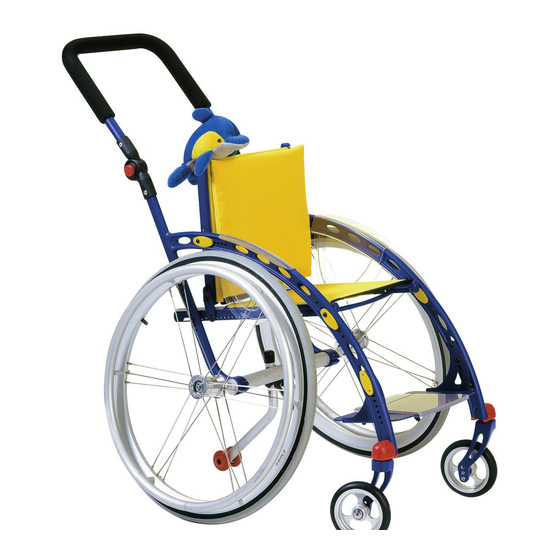
OVERVIEW The overview (fig. 1 and 2) shows the most important components of the wheelchair. Backrest Push bar Armrest Handrims Seat cushion / seat belt Support wheel Footplate Driving wheel Steering wheel Pressure Brake... -
Page 9: Driving Behavior
DRIVING BEHAVIOR SUPPLEMENTARY USER/ SAFETY INFORMATION The tuning of the driving features and • Clean, passive lighting is required your personal needs will be achieved for driving in public traffic. for the time being after a brief “intro- • Do not throw or drop parts belon- ductory “... - Page 10 • • Never leave children in the Tyres are made of a rubber mixtu- wheelchair unattended. re and can leave permanent or dif- ficult-to-remove marks on some • Always approach small obstacles, surfaces (e.g. plastic, wooden or e.g. steps or curbs, slowly and at a parquet flooring, carpets, mats).
-
Page 11: Brake
BRAKE The locking brake belongs to the most important safety features of a wheelchair and is available as a pres- sure brake (fig. 4). Attention: Please observe the Maintenance In- structions as well as instructions in the section General Safety Informa- tion and Brakes in the brochure Safety information Mechanical wheelchairs! -
Page 12: Pressure Brake
PRESSURE BRAKE Function as operating brakes Press both brake levers (fig. 5/ ) only slightly forward. – This way the wheelchair brakes down slowly. Locking the pressure brakes To secure the wheelchair against any unintentional rolling, press both bra- ke levers forward all the way (fig. 5). Note: It should not be possible to push the wheelchair forward when both... -
Page 13: Foot Plate
FOOT PLATE A footplate is available (fig. 8) that can be adjusted in height, angle and depth to the individual requirements of the child. Adjusting the height of the foot plate – Screw out the attachment screws (fig. 9/ ) on both sides. –... -
Page 14: Adjusting The Angle Of The Footplates
Adjusting the angle of the footplates The footplate can be adjusted in ang- le from +/- 10°. – Unscrew the attachment screw (fig. ) on each side. – Loosen the attachment screw (fig. ) on each side, but do not pull them out. -
Page 15: Skid Protection
SKID PROTECTION The transparent skid protector gives a secure hold for the feet. Additionally it can be used as a window for infor- mation or pictures (fig. 11). Attaching the skid protector – Insert the skid protector (fig. 12/ in the front and press the back down. -
Page 16: Armrests
ARMRESTS The side elements (fig. 13/ ) can be removed and inserted steplessly on the frame. The side elements serve at the same time as armrest, clothes guard and wind guard. Attention: No not grab between the frame and seat. – Danger of accidents! •... -
Page 17: Seat Belt
SEAT BELT Adjustment of seat inclination The seat belt (fig. 14/ ) can be adjus- ted in angle from 0° to 6°. – Unscrew the attachment screw (fig. ) on each side. – Loosen the attachment screw (fig. ) on each side, but do not pull them out. -
Page 18: Adjusting The Seat Depth
Adjusting the seat depth The seatbelt (fig. 14/ ) can be reposi- tioned according to the length of the thigh. – Pull or lever the clamping piece (fig. 17/ or fig. 18/ ) out of the seat tube on both sides, if necessa- ry apply a screwdriver. -
Page 19: Backrest
BACKREST Fitting the back belt The tension of the backrest is adjus- table. – Pull the back cover off and fold it to the front (fig. 19). – Open the Velcro fastener of the belt that you wish to adjust and close it again after adjustment. -
Page 20: Adjusting The Backrest Angle
Adjusting the backrest angle The angle of the backrest (fig. 20) can be adjusted from -6° to +9°. The basic position of the backrest is 90° to the not angled seat surface. – Unscrew the attachment screw (fig. ) on each side. – Hold onto the nut (fig. -
Page 21: Push Bar
PUSH BAR The height adjustable push bar (fig. 23) lets itself be adjusted to the require- ments of the attendant and be swi- velled down for transport (fig. 26). Height adjustment – Press the locking button (fig. 24/ to the side on both sides and ad- just the push bar evenly on both sides to the desired height. -
Page 22: Support Wheel
SUPPORT WHEEL The centred support castor (fig. 27) provides an increased tilting stability and can be swivelled forward under the seat (fig. 28). Attention: In certain situations support wheels do not provide sufficient protec- tion against overturning. Definitely refrain from the follo- wing: Leaning the upper body far back. -
Page 23: Height Adjustment
Height adjustment The support castor can be adjusted in height. – Remove the clamping screw (fig. – Adjust the support castor accordin- gly in height. – Assemble the screwed connection (fig. 29/ Attention: In order to raise the tilting stabili- ty never drive without the support castor swivelled to the back. -
Page 24: Drive Wheels
DRIVE WHEELS The driving wheels can be removed and reassembled without any tools. No person may be seated in the wheelchair during assembly or rem- oval. The wheelchair must stand on a level and firm surface. Before starting the disassembly work, support the fra- me to prevent the wheelchair from tipping over and secure it to prevent an unwanted movement or tipping... -
Page 25: Handrims
Handrims All handrims are designed for a dis- tance to the driving wheel of 15 mm (standard setting) and 25 mm (fig.32 and 31). Attention: Replacement of handrims or mo- dification of handrim distances should always be carried out by your specialist workshop. -
Page 26: Options
OPTIONS Options are not a part of the standard scope of supply. Note: Options from other companies can cause malfunctions. SPOKE GUARD The hand and spoke guard prevents injuries to the hands occurring by jam- ming in the turning spokes of the wheels, as well as damage to the spo- kes. -
Page 27: Loading And Transportation
LOADING AND TRANS- Transport security PORTATION Carry out the following steps when the wheelchair is located in the transport Safety informations vehicle: When transporting the wheelchair in – Stow all disassembled wheelchair vehicles, the child should leave the parts in a secure and protected way. wheelchair and sit on a suitable seat –... -
Page 28: Safety Informations
TRANSPORT IN HANDICAP- Note: PED TRANSPORT AUTOMO- Suitable fixing points can usually BILE be found in the car and in the ve- hicle operating manual. Note: For transport in vehicles we recom- Before transporting the wheelchair, mend to leave the wheelchair and ask your car dealer how to secure sit on a suitable seat in the vehicle. -
Page 29: Product Liability Instructions
Safety informations Note: The headrest on the wheelchair ser- When transporting a person, make ves as a support for the posture of sure that there are no objects jam- the head, not as a transport securi- med underneath the straps! – Thus ty. -
Page 30: Service
SERVICE Plastic parts The side elements and similar consist MAINTENANCE of high value plastic parts. Take care of these by means of standard plastics As is the case with every other techni- cleaning agents. Always observe the cal product, your Standard wheelchair specific product information. -
Page 31: Customer Service
CUSTOMER SERVICE TOOLS In case you have any questions or need For adjustments to the wheelchair the help please contact your specialist dea- following tools are required: ler who can assume counselling, ser- 1 xHexagonal stud wrench WW* 3 vice and repairs. 1 xHexagonal stud wrench WW* 4 SPARE PARTS Spare parts can only be ordered from... -
Page 32: Flat Tyre
FLAT TYRE Sitting in the wheelchair during a wheel change is not permitted. The wheelchair must stand on a level and firm surface. Before starting the disas- sembly work, support the frame to prevent the wheelchair from tipping over and secure it to prevent an un- wanted movement or tipping over. -
Page 33: Steering Wheels
STEERING WHEELS Exchanging the steering wheels – Before replacement or repair the steering wheel axle (fig. 36/ ) is to be disassembled. Note: Take note of the arrangement of all sleeves and washers used. The valve points outwards. Steering wheel position The position of the steering wheel and steering fork depends on the diame- ter of the steering wheel:... -
Page 34: Maintenance Instructions
MAINTENANCE INSTRUCTIONS WHEN WHAT Remark Test brakes for fault- Carry out test yourself Before starting out less operation or with a helper. Activate brake lever to the limit. The locked wheels should not be able to turn under ope- rating conditions. If they can still turn, the brakes must be repaired by an specialist workshop. - Page 35 MAINTENANCE INSTRUCTIONS WHEN WHAT Remark Before starting out Check air pressure of Do it yourself or with the tyres the aid of a helper. For this use an air pres- Standard tyres: sure gauge or, if not 4 bar = 56 psi available conduct the High-pressure tyres: “thumb pressure me-...
- Page 36 MAINTENANCE INSTRUCTIONS WHEN WHAT Remark Every 8 weeks Lubricate the follo- Do it yourself or with (depending on distance wing components the aid of a helper. covered) with a few drops of oil Components must be free from used oil resi- –...
-
Page 37: Technical Data
All data within the following table relates to the standard version of the stated model. Dimensional tolerance is +/-1.5 cm, +/-2° Model ..........CHILDREN’S WHEELCHAIR BRIX 1.123 There are two frames available for the following age groups: – Mini Code 351 for children of 2 to 5 years –... - Page 38 Backrest belt height Frame Mini and Midi: ................ 20 to 34 cm Seat inclination Frame Mini and Midi: ................0° to 6° Backrest reclining Frame Mini and Midi: ....... adjustable in 3°-steps from -6° to +9° (The basic position of the backrest is 90° to the not angled seat surface) Thigh length Without seat cushion: ................
- Page 39 Weights Max. permissible total weight*: ..............49 kg Max. permissible user weight (including additional load): ......40 kg Empty weight: ....................9 kg (with armrests and drive wheels) Transport weight: ..................5.5 kg (without drive wheels) Note: The maximum total load is calcu- lated on the basis of the unloaded weight of the wheelchair and the maximum passenger weight.
-
Page 40: Notes
NOTES... - Page 41 NOTES...
-
Page 42: Guarantee
GUARANTEE Damage to surfaces, tyres, damage due to screws and washers which have worked loose or worn out attachment We accept a guaranty for this product holes due to frequent assembly and according to the legal regulations. dismantling are not covered by this Apart from this we warrant: guarantee. -
Page 43: Guarantee Note
GUARANTEE NOTE Fill in the details! If necessary, copy and return. Guarantee Model designation: Delivery note no.: Vehicle ID No. (Fz-I-Nr.) (view type pla- Date of delivery: te): Stamp of the authorized dealer:... - Page 44 Stamp of the authorized dealer: The Motivation. MEYRA • Wilhelm Meyer GmbH & Co. KG Company address: Meyra-Ring 2 D-32689 Kalletal-Kalldorf Telephone +49 (0)5733 922 - 311 Fax +49 (0)5733 922 - 143 Email: info@meyra.de Internet: http://www.meyra.de Postal address: P.O. Box 1703 • D-32591 Vlotho...