Table of Contents
Advertisement
Quick Links
Advertisement
Table of Contents

Related Manuals for Denso AT20B-SM


Summary of Contents for Denso AT20B-SM
- Page 1 Barcode Handy Scanner AT20B-SM AT21B-SM User’s Manual...
- Page 2 Copyright © DENSO WAVE INCORPORATED, 2011 All rights reserved. No part of this publication may be reproduced in any form or by any means without permission in writing from the publisher. All products and company names mentioned in this manual are trademarks or registered trademarks of their respective holders.
-
Page 3: Table Of Contents
Contents Preface ................................ i Customer Registration and Inquiries ......................ii SAFETY PRECAUTIONS.......................... iii Care and Maintenance ..........................vii Chapter 1 Names and Functions ......................1 Chapter 2 Preparation ..........................2 2.1 Operating Environment for the Use of USB Interface ..............2 2.2 Connecting the Interface Cable to the Scanner ................3 Chapter 3 Connection to the Host Computer...................3 Chapter 3 Connection to the Host Computer...................4 3.1 Using the RS-232C Interface ......................4... - Page 4 Chapter 10 Parameters and Defaults ....................52 Chapter 11 Bar coded Parameter Menu ....................68 11.1 Parameter Setting Procedure Using the Bar coded Parameter Menu ........68 11.2 Bar coded Parameter Menu....................69 Chapter 12 Troubleshooting ........................89 Appendix 1 Specifications........................91 Appendix 2 Control Commands ......................92 Appendix 3 Interface Specifications.......................95...
-
Page 5: Preface
DENSO WAVE; (ii) the use of DENSO WAVE’s products in a manner for which the same were not intended nor designed; or (iii) any modification of DENSO WAVE’s products by other(s) than DENSO... -
Page 6: Customer Registration And Inquiries
Customer Registration and Inquiries Customer Registration To allow us to provide our customers with comprehensive service and support, we request that all customers complete a Member Registration Form. Registered members will be offered the following privileges. Latest upgrade information ... -
Page 7: Safety Precautions
SAFETY PRECAUTIONS Be sure to observe all these safety precautions. Please READ through these instructions carefully. They will enable you to use the scanner correctly. Always keep this manual nearby for speedy reference. Strict observance of these warnings and cautions is a MUST for preventing accidents that could result in bodily injury and substantial property damage. - Page 8 To System Designers: When introducing the scanner in those systems that could affect human lives (e.g., medicines management system), develop applications carefully through redundancy and safety design which avoids the feasibility of affecting human lives even if a data error occurs. ...
- Page 9 Never disassemble or modify the scanner; doing so could result in an accident such as break or fire. Doing so could result in a fire or electrical shock. Never disassemble Do not put the scanner on an unstable or inclined plane. The scanner may drop, creating injuries.
- Page 10 When disconnecting the AC adapter from the wall socket, hold the AC adapter body not the power cable. The power cable may be broken, resulting in a burnt AC adapter, electrical shock, or fire. If the interface cable is damaged (e.g., exposed or broken lead wires), stop using it and contact your nearest dealer.
-
Page 11: Care And Maintenance
Care and Maintenance ■ Proper Care of the reading window Dust or dirt accumulating on the clear plate of the barcode reading window will affect reading performance. If you use the scanner in dusty areas, therefore, periodically check the clear plate and clean it if dusty. ... -
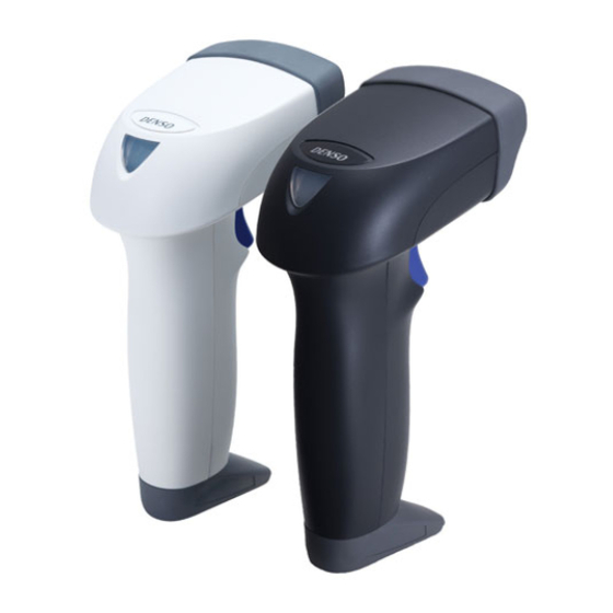
Page 12: Chapter 1 Names And Functions
Chapter 1 Names and Functions Reading window A Barcode is placed at this reading window. LED indicator Illuminates blue when reading is complete. Beep hole The beeper sounds when the Case scanner has read a barcode ・AT20B:Light gray successfully. ・AT21B:Black Trigger switch Press this switch to start Barcode reading. -
Page 13: Chapter 2 Preparation
* Registered users can download the configuration software (Scanner Setting) from QBdirect, their customer support section on the Denso Wave website at no extra charge. For further details on QBdirect or to register, visit the following URL. -
Page 14: Connecting The Interface Cable To The Scanner
2.2 Connecting the Interface Cable to the Scanner (1) Pull the connector cover of the interface cable off its connector as shown below. (2) Plug the interface cable connector into the connector located in the bottom of the scanner. Note: As shown below, hold the scanner body, align the mark on the cable connector with that on the scanner, and fully insert the interface cable connector. -
Page 15: Chapter 3 Connection To The Host Computer
Chapter 3 Connection to the Host Computer 3.1 Using the RS-232C Interface (1) AC adaptor-powered type ①Connect the RS-232C interface cable to the host computer. Scanner AC adapter RS-232C interface cable ②Plug the AC adapter into the DC power jack provided in the interface cable connector. Note: When disconnecting the interface cable or DC power jack, hold the connector housings not the cables. -
Page 16: Using The Usb Interface
3.2 Using the USB Interface The scanner receives and sends data from/to the host computer through the USB-COM interface or USB keyboard interface. You need to set up the device driver designed for the interface to be used. Notes for connecting the USB interface cable ... -
Page 17: Setting Up The Usb-Com Interface
3.2.1 Setting up the USB-COM interface Using the USB-COM interface requires installing the Active USB-COM port driver provided by DENSO WAVE to the host computer. The driver does not come with the scanner in a CD-ROM. It can be downloaded for free from our website at: http://www.qbdirect.net... -
Page 18: Setting Up The Usb Keyboard Interface
3.2.2 Setting up the USB keyboard interface The USB keyboard interface requires the USB device class driver for HID (Human Interface Device) which is included in Windows 98 or later Operating Systems and whose setup wizard will automatically run. You do not need to install the device driver. - Page 19 Windows XP (1) Switch the computer on to run Windows XP. Log on as an Administrator. (2) Connect the scanner’s USB interface cable to the computer or USB hub. (3) Wait for the Found New Hardware hint to pop up on the Windows task tray.
-
Page 20: Chapter 4 Reading Barcodes
Chapter 4 Reading Barcodes Bring the reading window to a target barcode and press the trigger switch. The marker beam comes on, indicating the scan range. The illumination LEDs light and the scanner reads the target barcode. (This operation is not required for the Continuous reading mode, Auto sensing mode and the Auto stand mode.) Adjust the center mark of the marker beam to the center of the Barcode. -
Page 21: Chapter 5 Setting Parameters
Note: The configuration software cannot be used when the USB keyboard interface mode is selected for the scanner. * Registered users can download the configuration software (Scanner Setting) from QBdirect, their customer support section on the Denso Wave website at no extra charge. For further details on QBdirect or to register, visit the following URL. http://www.qbdirect.net... -
Page 22: Chapter 6 Reading Control
Chapter 6 Reading Control Two types of reading controls are available--Trigger switch control and Software control. Trigger switch control: Pressing the trigger switch readies the scanner for reading. (Refer to Section 6.1.) Software control: Instead of pressing the trigger switch, you send control commands from the host computer via the RS-232C or USB-COM interface to ready the scanner for reading or put the scanner on standby. -
Page 23: Software Control
6.2 Software Control You can control the scanner by sending reading control commands from the host computer via the RS-232C or USB-COM interface, instead of pressing the trigger switch. Reading control commands include R, READON, LON, Z, READOFF and LOFF and are restricted by the trigger switch operating modes, as listed below. - Page 24 Note: Even if you do not bring a barcode label within the scan range, the illumination LEDs may come on when the ambient level of light changes or any shadows move within the scan range. Note: To enable the scanner to work properly in auto sensing mode, an ambient illuminance of at least 500 lx is required.
-
Page 25: Chapter 7 Reading Functions
Chapter 7 Reading Functions 7.1 Data Verification Mode The data verification mode verifies the barcode data read against the master data stored in the scanner and reports the match status with data output. Data verification read is available in two types--“n-point verification” and “2-point verification,” which can be selected with the configuration software (Scanner Setting). - Page 26 2-point verification Scan master registration 1) Switch the scanner to the data verification mode and select the RS-232C or USB-COM interface. The indicator LED lights in green. 2) Use the scanner to scan a master code to be registered. (The scanner operates in the trigger switch operating mode currently set.) After the registration of master data, the indicator LED turns blue and then goes OFF.
-
Page 27: Specifying A Verification Object
7.1.2 Specifying a verification object You can specify two types of verification objects--data string and data block. For data string verification, specify the verification start position and the number of characters to be verified. For data block verification, specify one of the data blocks delimited by commas in the CSV format. -
Page 28: Verification Result Output
7.1.3 Verification result output (1) Report of match / mismatch status You can select any of the following report types using the configuration software (ScannerSetting). Selecting “Disable transmission” reports nothing. Setting If there is a match: If there is a mismatch: 1... -
Page 29: Data Editing
7.2 Data Editing You can edit and output code data read, in any of the three data edit modes--“data extraction mode,” “data conversion mode” and “blocksorting mode.” These data edit modes can be selected with the configuration software (Scanner Setting). The default is “No editing.” 7.2.1 Data extraction mode This mode offers three extraction choices--“data string,”... - Page 30 Extraction start and end positions “Extraction start position” “Extraction end position” Head position nth position Tail position Tail position nth position By n positions from the start position nth position The n can be 1 through 9999. Note that if the extraction start position is specified as nth position, the extraction end position should be equal to or greater than the extraction start position.
-
Page 31: Extracting Data Blocks
7.2.1.2 Extracting data blocks If data read is in the comma-delimited CSV format, the scanner extracts data blocks specified by the data block numbers from a code specified by the “Code type” and then outputs it in the data transmission format selected in the scanner (see Chapter 9, Section 9.4). - Page 32 Example Code type : CODE128, Data : (See the table below.) Header : STX, Terminator : ETX, Scanner ID : Disable, Code ID mark : Disable, Transmission of the number of digits : Disable, Prefix / Suffix : None, BCC : Disable Data block Extraction conditions Data read...
-
Page 33: Extracting Ai (Application Identifier)-Prefixed Strings
7.2.1.3 Extracting AI (Application Identifier)-prefixed strings If the scanner reads any of GS1-128 (EAN-128) and GS1DataBar (RSS) symbols, it edits the data according to AI and outputs it in the data transmission format selected in the scanner (see Chapter 9, Section 9.4). The “AI-prefixed string”... - Page 34 Example Data read : (01)94901234567894(11)030808(13)030810(17)040208(17)040305 Header : STX, Terminator : ETX, Scanner ID : Disable, Code ID mark : Disable, Transmission of the number of digits : Disable, Prefix/Suffix : None, BCC : Disable Extraction conditions AI specified Delimiter Output data “Transmit data 01,11,17 [STX]94901234567894,030808,040208[ETX]...
- Page 35 (2) AI parenthesizing mode In this mode, the scanner parenthesizes AI contained in data read and outputs the edited data according to the extraction conditions. Extraction conditions Extraction conditions Setting data “Transmit data regardless of the results” Permit/Prohibit If the scanner fails to extract an AI-prefixed element string when the “Transmit data regardless of the results” is permitted, it outputs the data read as is without editing.
- Page 36 (3) AI table In the AI-prefixed string extraction, the scanner edits data according to the Application Identifiers (AI) defined below. Format Description n2+n18 Serial Shipping Container Code (SSCC) n2+n14 Global Trade Item Number (GTIN) n2+n14 GTIN of Trade Items Contained in a logistic unit (For Use with AI 37 Only) n2+n14 Reserved.
- Page 37 Format Description 320n n4+n6 Net Weight, Pounds (***) 321n n4+n6 Length or 1st Dimension, Feet (***) 322n n4+n6 Length or 1st Dimension, Yards (***) 323n n4+n6 Width, Diameter, or 2nd Dimension, Inches (***) 324n n4+n6 Width, Diameter, or 2nd Dimension, Feet (***) 325n n4+n6 Width, Diameter, or 2nd Dimension, Yards (***)
- Page 38 Format Description 353n n4+n6 Area, Square Inches, Logistics (***) 354n n4+n6 Area, Square Feet, Logistics (***) 355n n4+n6 Area, Square Yards, Logistics (***) 356n n4+n6 Net Weight, Troy Ounces (***) 357n n4+n6 Net Volume, Ounces (***) 360n n4+n6 Volume, Quarts (***) 361n n4+n6 Volume, Gallons (***)
- Page 39 Format Description n3+n3+an..9 Ship to (Deliver to) Postal Code with Three-Digit ISO Country Code Prefix n3+n3 Country of Origin of a Trade Item n3+n15 Country of Initial Processing n3+n3 Country of Processing n3+n3 Country of Disassembly n3+n3 Country of Final Processing n2+n4+n7+an Carrier Assigned Tracking Number ..10+n1...
- Page 40 Format Description n2+an..30 Company Internal Information--Company n2+an..30 Company Internal Information--Company n2+an..30 Company Internal Information--Company n2+an..30 Company Internal Information--Company n2+an..30 Company Internal Information--Carrier n2+an..30 Company Internal Information--Carrier n2+an..30 Company Internal Information--Company n2+an..30 Company Internal Information--Company n2+an..30 Company Internal Information To indicate only year and month, DD must be filled with “00”. (**) n indicates the length of data.
-
Page 41: Data Conversion Mode
7.2.2 Data conversion mode If the scanner reads a barcode specified by the “Code type” in this mode, it searches the data read for the specified string (max. 16 ASCII characters), substitutes it with the specified conversion string (max. 16 ASCII characters), and outputs it in the data transmission format selected in the scanner (see Chapter 9, Section 9.4). -
Page 42: Blocksorting Mode
7.2.3 Block sorting mode The scanner splits barcode data read into a maximum of 5 blocks at the specified separate positions, sorts those blocks in the specified order, and outputs it in the data transmission format selected in the scanner (see Chapter 9, Section 9.4). -
Page 43: Chapter 8 Beeper, Indicator Led
Chapter 8 Beeper, Indicator LED 8.1 Beeper (1) Beeping The scanner emits a short or long beeps, once or a couple of times as described below. (Refer to Section 8.3 for details of beeper in various states) You can disable the beeper using the Bar coded parameter menu or configuration software (ScannerSetting). In any of the following cases, however, the beeper sounds regardless of that beeper setting: - when you make settings by reading the Bar coded parameter menu, - when the scanner receives a beeper-ON command from the host computer,... -
Page 44: Indicator Led
8.2 Indicator LED The indicator LED lights or flashes in blue, green or red with scanner status. (Refer to Section 8.3 for details of indicator LED in various states) The indicator LED can be disabled with the Bar coded parameter menu or configuration software (Scanner Setting). -
Page 45: Beeping, Indicator Leds With Scanner Status
8.3 Beeping, Indicator LEDs with scanner status ■ Normal operation Status Beeping Indication LED 1 short beep A read of a bar code is successfully complete Lights in blue (Note 1) (Note 2) Barcode data read matches the master data in the n-point verification 1 short beep (Note 1) (Note 2) scan mode... - Page 46 Indication Status Beeping No master data has been registered in the n-point verification scan Lights in red mode (Repeating)
-
Page 47: Chapter 9 Communication
Chapter 9 Communication 9.1 RS-232C Interface With the RS-232C interface being selected, the scanner uses asynchronous data transmission and communicates with the host computer or external equipment via the RS-232C. You can set various communications conditions using the Bar coded parameter menu or configuration software (Scanner Setting). Barcode data read is transferred in the following format. -
Page 48: Usb-Com Interface
* Registered users can download the keyboard interface software (QR_kbif) from QBdirect, their customer support section on the Denso Wave website at no extra charge. For further details on QBdirect or to register, visit the following URL. http://www.qbdirect.net... - Page 49 Communication protocols You can select either no protocol mode or ACK/NAK mode. No protocol mode (default) If the CTS signal is at a high level (Enable transmission), the scanner transmits barcode data read. Note: The configuration software (Scanner Setting) provides CTS timeout settings from 100 ms to 9.9 s in 100-ms increments and two CTS signal control choices “controlled”...
-
Page 50: Usb Keyboard Interface
9.3 USB Keyboard Interface The USB keyboard interface requires no dedicated device driver. Data read by the scanner can be entered to the cursor position in your application. The USB keyboard interface operates in conformity with the following: - Universal Serial Bus (USB) Device Class Definition for Human Interface Devices (HID) Version 1.11 - Universal Serial Bus (USB) HID Usage Tables Version 1.11 keyboard (1) CAPS Lock state Select the CAPS Lock ON or OFF to match the state of the connected keyboard. -
Page 51: Communication Format
9.4 Communication Format Select one of the following two data transmission formats. No. of digit Code ID Scanner Header Prefix Code data Suffix Terminator mark n1 n2 n3 N4 No. of digit Code ID Scanner Header Prefix Code data Suffix Terminator mark n1 n2 n3 n4... - Page 52 (5) Code ID mark This optional field specifies the code ID mark identifying a barcode symbology. Five types of code ID marks (Type 1, Type 2, Type 3, Type 4, and user-defined) are available as listed below. The code mark type 4 has two output modes “Coupling” and “Separate.” Coupling : In a UPC/EAN symbol with an add-on, the same code ID mark is assigned to the main portion and the add-on portion of the symbol.
- Page 53 CODABAR (NW-7) CODE93 CODE128 GS1-128 (EAN-128) Plessey (Note1) GS1 DataBar (RSS) Note 1 : GS1 DataBar (RSS) refer to all of the following code: GS1 DataBar Omnidirectional (RSS-14), GS1 DataBar Truncated (RSS-14 Truncated), GS1 DataBar Limited (RSS-14 Limited), GS1 DataBar Stacked (RSS-14 Stacked), GS1 DataBar Expanded (RSS Expanded), GS1 DataBar Stacked Omnidirectional (RSS-14 Stacked Omnidirectional) and GS1 DataBar Expanded Stacked (RSS Expanded Stacked).
- Page 54 (6) Number of digits Indicates the number of barcode data digits in four digits (four bytes) or two digits (two bytes), however, the number of digits is omitted for UPC and EAN codes(excluding GS1-128(EAN-128)). It is possible to select whether transfer of the number of digits is required. When four digits(four bytes) transferred: n1:...
- Page 55 UPC-E You can select whether or not to transmit the padding character “0,” number system character “S,” and a check digit to the host. Disabling the transmission of the number system character “S” automatically disables the transmission of the padding character “0.” The conversion to the GTIN format or to the UPC-A are selectable.
- Page 56 EAN-13 You can select whether or not to transmit the two prefix characters “P ” and “P ” and a check digit to the host. The conversion to the ISBN/ISSN format is selectable. Enabling the conversion allows EAN-13 code with prefix characters 978 or 979 to be converted into the ISBN format, and EAN-13 code with prefix characters 977, into the ISSN format.
- Page 57 EAN-8 with add-on A code ID mark precedes add-on code data under the conditions “Code ID mark: Type 4” and “Code ID mark output mode: Separating.” (For details about the code ID mark, refer to (5) Code ID mark) The conversion to the GTIN format is selectable. For the GTIN format conversion, refer to Section 9.5. When the conversion to the GTIN format is disabled, the following formats apply.
-
Page 58: Gtin Format Conversion
9.5 GTIN Format Conversion Enabling the GTIN (Global Trade Item Number) format conversion allows UPC-A, UPC-E, EAN-13, EAN-8, and Interleaved 2 of 5 (14-digit) data to output in the GTIN format. It also allows GS1 DataBar (RSS) and GS1-128 (EAN-128) data in the GTIN format to output in the EAN format (product code format). Note : Under any of the following conditions, the GTIN format conversion is invalid. - Page 59 UPC-E Data read 0 : Adjust the number of digits Conversion to 16-digit GTIN format (AI “01” and PI added) =0 - 2 0 1 PI 0 0 X 0 0 0 0 X 0 1 PI 0 0 X 0 0 0 0 0 X 0 1 PI 0 0 X 0 0 0 0 0 X...
- Page 60 EAN-13 Data read : Prefix characters Conversion to 16-digit GTIN format (AI “01” and PI added) 0 1 PI P Check digits are calculated again and transferred regardless of the transmission specified. Conversion to 14-digit GTIN format (PI added) PI P Check digits are calculated again and transferred regardless of the transmission specified.
- Page 61 EAN-8 with add-on Data read With 2-digit add-on: C/D X With 5-digit add-on: C/D X : Prefix characters : Add-on code data 6-10 Conversion to 16-digit GTIN format (AI “01” and PI added) With 2-digit add-on: 0 1 PI 0 0 0 0 0 P C/D X With 5-digit add-on: 0 1 PI 0 0 0 0 0 P...
- Page 62 (2) Conversion from GS1 DataBar (RSS) / GS1-128 (EAN-128) in GTIN format to EAN format GS1 DataBar (RSS) or GS1-128 (EAN-128) data read in the GTIN format (16-digit with AI “01”) can be converted to the EAN format if the conversion is enabled. The conversion provides two choices--13- or 14-digit EAN formats.
-
Page 63: Chapter 10 Parameters And Defaults
Chapter 10 Parameters and Defaults Parameters in the chart below can be selected with Bar coded parameter menu or configuration software (Scanner Setting). However, shaded parameters can be selected only with the configuration software (Scanner Setting). All parameters are selected as default setting at shipment. (1) Reading Mode Parameter Selection Item Parameter... - Page 64 (3) RS-232C Interface Parameter Selection Only valid when Interface Selection has been selected RS-232C interface. Item Parameter Default Reference No protocol mode Chapter 9 Communication mode Section 9.1 (1) ACK/NAK mode 4800 bps 9600 bps 19200 bps Chapter 9 Transmission speed Section 9.1 (3) 38400 bps...
- Page 65 (5) USB keyboard Interface Parameter Selection Only valid when Interface Selection has been selected USB keyboard interface. Item Parameter Default Reference Auto setting Chapter 9 CAPS mode Section 9.3 (1) Manual setting (NOTE 1) CAPS LOCK OFF Chapter 9 CAPS LOCK state Section 9.3 (1) CAPS LOCK ON...
- Page 66 Item Parameter Default Reference Enabled Special key (NOTE 4) transmission mode Disabled 1 msec 5 msec 10 msec Chapter 9 Data transmission interval 15 msec Section 9.3 (4) 30 msec 50 msec 100 msec Enabled Chapter 9 Remote wakeup Section 9.3 (5) Disabled...
- Page 67 (6) Data Transmission Format Selection Common to All the Interfaces Item Parameter Default Reference Enabled Chapter 9 Code mark transmission Section 9.4 Disabled Before the prefix Chapter 9 Code mark position Section 9.4 After the prefix Type1 (DENSO1) Type2 (DENSO2) Chapter 9 Code mark type...
- Page 68 (7) Data Transmission Format Selection for RS-232C/USB-COM Item Parameter Default Reference None Header User-defined None Chapter 9 Section 9.4 (1) Terminator CR + LF User-defined Enabled Chapter 9 BCC transmission Section 9.4 Disabled : These can be selected only with the configuration software (Scanner Setting).
- Page 69 (8) Data Transmission Format Selection for USB Keyboard Interface Item Parameter Default Reference None CR + LF Header ENTER ENTER(Right CTRL) ← ↑ → ↓ User-defined Chapter 9 Section 9.4 (1) None CR + LF Terminator ENTER ENTER(Right CTRL) ←...
- Page 70 (9) Barcode Selections UPC-A/E、EAN-13/8 Item Parameter Default Reference Enabled Chapter 9 Reading UPC-A & EAN-13 Section 9.4 Disabled Enabled C/D transmission of UPC-A Disabled Enabled Transmission of UPC-A number system characters Disabled Chapter 9 Section 9.4 Transmission of head Enabled character to adjust...
- Page 71 Item Parameter Default Reference Enabled Chapter 9 Reading EAN-8 Section 9.4 Disabled Enabled C/D transmission of EAN-8 Disabled Enabled Conversion from EAN-8 to EAN-13 Disabled Enabled Reading 2-digit UPC/EAN add-on Disabled Chapter 9 Section 9.4 Enabled Reading 5-digit ...
- Page 72 CODABAR(NW-7) Item Parameter Default Reference Enabled without C/D Reading CODABAR(NW-7) Enabled with C/D Chapter 9 Disabled Section 9.4 Enabled C/D transmission of CODABAR (NW-7) Disabled Minimum number of readable 4 digits digits for CODABAR(NW-7) 3 to 99 digits (NOTE 1) (incl.
- Page 73 CODE128, GS1-128 (EAN-128) Item Parameter Default Reference Enabled Reading CODE128 Chapter 9 Disabled Section 9.4 Enabled (NOTE 2) Reading GS1-128 (EAN-128) Disabled Minimum number of readable 1 digit 1 to 99 digits digits for CODE128 (excl. start/stop codes and (NOTE 1) Maximum number of readable 1-digit C/D)
- Page 74 Plessey Item Parameter Default Reference Enabled Reading Plessey Disabled Single Mode of reading Plessey Dual Minimum number of readable 4 digits digits for Plessey 4 to 99 digits (NOTE 1) (incl. 2-digits C/D) Maximum number of readable 99 digits digits for Plessey NOTE 1 : The parameter setting range is not equal to the number of Scanner’s readable digits.
- Page 75 (10) Trigger Switch Control Item Parameter Default Reference Auto off mode Momentary switching mode Momentary switching mode Chapter 6 (Inverted type) Section 6.1 Alternate switching mode Trigger switch control Continuous reading mode 1 Continuous reading mode 2 Auto sensing mode Chapter 6 Section 6.3 Auto stand mode...
- Page 76 (11) Beeper and LED indicator Item Parameter Default Reference Enabled Beeping sound Disabled Low(2.8 kHz) Beeper frequency Medium(3.0 kHz) High(4.0 kHz) Chapter 8 Short(60 msec) Section 8.1 Beeper sound duration Medium(80 msec) Long(120 msec) High Beeping volume level Medium ...
- Page 77 (12) Parameter Selection for Data Verification and Data Editing Item Parameter Default Reference Data string verification Verification method Data block verification Enabled Preset master registration Disabled Starting point of data 1 to 999 digits 1 digit string verification in ASCII characters Number of digits to be verified for data string...
- Page 78 Item Parameter Default Reference Number of extracted digits 1 to 99 digits Not defined (3 blocks max) in ASCII characters NOTE 1 : “Any code” means all data can be edited. : These can be selected only with the configuration software (Scanner Setting). Item Parameter Default...
-
Page 79: Chapter 11 Bar Coded Parameter Menu
Chapter 11 Bar coded Parameter Menu 11.1 Parameter Setting Procedure Using the Bar coded Parameter Menu Use the scanner to scan the “Start setting” Barcode symbol. Start setting ↓ Three beeps Scan parameter Scan necessary parameter setting Barcode symbols. setting Barcode symbols. -
Page 80: Bar Coded Parameter Menu
11.2 Bar coded Parameter Menu ■ Menu control (Starting/Ending the Setting Procedure and Reverting to Defaults) Start setting End setting All defaults Cancel The beeper volume can be set by reading the following Barcode symbol only. No “Start setting” or “End setting”... - Page 81 ■ Communications parameters for RS-232C interface Procedure < No protocol mode > ACK/NAK mode Transmission speed 4800bps < 9600bps > 19200bps 38400bps 57600bps 115200bps Data bit 7bits < 8bits > Parity < None > Odd parity Even parity...
- Page 82 Stop bit < 1 bit > 2 bits CTS signal monitoring < Not controlled > Controlled Header < None > Terminator < CR > CR/LF None Transmission of BCC < Disable > Enable...
- Page 83 ■ Communications parameters for USB-COM interface Procedure < No protocol mode > ACK/NAK mode CTS signal monitoring < Not controlled > Controlled Header < None > Terminator < CR > CR/LF None...
- Page 84 Transmission of BCC < Disable > Enable...
- Page 85 ■ Communications parameters for USB keyboard interface Caps Lock mode < Manual(OFF) > Manual(ON) Auto Keyboard type < U.S.English (101 Keyboard) > Germany (102 Keyboard) French (102 Keyboard) U.K.English (102 Keyboard) Italian (102 Keyboard) Swedish (102 Keyboard) Japanese(106 Keyboard)
- Page 86 Data trasmission interval < 1ms > 10ms 15ms 30ms 50ms 100ms Numeric data transmission format < Inboard numeric keys > Numeric keypad Special key transmission mode Enable < Disable >...
- Page 87 Header (USB keyboard interface) < None > CR+LF ENTER Right Ctrl ← ↑ → ↓...
- Page 88 Terminator (USB keyboard interface) None CR+LF < ENTER > Right Ctrl ← ↑ → ↓...
- Page 89 ■ Data transmission format Transmission of code ID mark Enable < Disable > Tranmission of the number of digits Enable in 4 digits Enable in 2 digits < Disable >...
- Page 90 UPC-A/-E and EAN-13/-8 Reading UPC-A, UPC-E, EAN-13 and EAN-8 < Enable > Disable Reading UPC/EAN add-on Enable in 2-digit add-on < Disable in 2-digit add-on > Enable in 5-digit add-on < Disable in 5-digit add-on > Standard 2 of 5 Reading Standard 2 of 5 Enable without a chek digit Enable with a check digit...
- Page 91 Interleaved 2 of 5 Reading Interleaved 2 of 5 < Enable without a chek digit > Enable with a check digit Disable Check digit transmission < Enable > Disable CODABAR (NW-7) Reading CODABAR (NW-7) < Enable without a check digit > Enable with a check digit Disable Check digit transmission...
- Page 92 Transmission of start / stop codes for CODABAR (NW-7) < Transmit a/b/c/d > Transmit A/B/C/D Disable CODE32 Conversion from CODE39 to CODE32 Enable < Disable > Transmission of the leading “A” of CODE32 Enable < Disable > Check digit confirmation of CODE32 Enable <...
- Page 93 CODE39 Reading CODE39 < Enable without a check digit > Enable with a check digit Disable Check digit transmission < Enable > Disable Transmission of start / stop codes for CODE39 Enable < Disable > Conversion to CODE39 Full ASCII Enable <...
- Page 94 CODE128/GS1-128(EAN-128) Reading CODE128/GS1-128(EAN-128) < Enable > Disable FNC1 transmission of CODE128 < Convert to GS before transmission > Disable FNC1 transmission of GS1-128(EAN-128) < Convert to GS before transmission > Disable Reading MSI Enable without a check digit Enable with a check digit(1-digit) Enable with a check digit(2-digit) <...
- Page 95 Plessey Reading Plessey Enable < Disable > Reading type of Plessy < Dual > Single GS1 DataBar (RSS) Reading GS1 DataBar Omnidirectional, GS1 DataBar Truncated Enable < Disable > Reading GS1 DataBar Stacked, GS1 DataBar Stacked Omnidirectional Enable < Disable > Reading GS1 DataBar Limited Enable <...
- Page 96 Reading GS1 DataBar Expanded Enable < Disable > Reading GS1 DataBar Expanded Stacked Enable < Disable > FNC1 transmission of GS1 DataBar Expanded < Convert to GS before transmission > Disable...
-
Page 97: Trigger Switch Control
■ Trigger switch control Trigger switch control < Auto-off mode > Momentary switching mode Momentary switching mode(Reverse type) Alternate switching mode Continuous reading mode 1 Continuous reading mode 2 Auto sensing mode Auto stand mode Auto-off reading mode setting < Normal > One shot 1sec One shot 2sec One shot 3sec... - Page 98 Auto sensing barcode detection level High < Medium >...
- Page 99 ■ Beeper/Indicator LED Beeper control < Enable > Disable Beeper frequency < Medium > High Beeper sound duration Short(60ms) < Medium(80ms) > Long(120ms) LED indicator < Enable > Disable...
-
Page 100: Chapter 12 Troubleshooting
Chapter 12 Troubleshooting ① Cannot scan bar codes. Trouble ② Reading data is not right. ③ Code data cannot be displayed normally on the computer screen. ④ Even after installation of the Active USB-COM port driver, “Connected” is not shown. ■Barcode label Trouble Cause... - Page 101 USB Keyboard interface : Trouble Cause Countermeasure ②③ The keyboard type selected not match Select the same keyboard type as one that is set up in the host one that is set up in the host computer. computer.(You can check the computer’s keyboard type by clicking My Computer|Control Panel|Keyboard|Hardware.) ②③...
-
Page 102: Appendix 1 Specifications
Appendix 1 Specifications Item AT20B-SM / AT21B-SM Reading Readable codes EAN-13, EAN-8, UPC-A, UPC-E, UPC/EAN with Add-on, specifications Interleaved 2 of 5, Standard 2 of 5, Code 32, Code 39, Codabar (NW-7), Code 93, Code 128, GS1-128(EAN-128), MSI, Plessey, GS1 DataBar Omnidirectional (RSS-14), GS1 DataBar Truncated... -
Page 103: Appendix 2 Control Commands
Appendix 2 Control Commands Control commands refer to commands that are exchanged between the host computer and the scanner via the communications line. Some of the control commands that the host computer issues are functionally equivalent to some parameters that can be set with the Bar coded parameter menu (refer to Chapter 11). - Page 104 Transfer Direction Control Function Scanner Host Commands Trigger switch control U1 : Auto-off mode U2 : Momentary switching mode U3 : Alternate switching mode U4 : Continuos reading mode 1 U5 : Continuos reading mode 2 U6 : Auto sensing mode U7 : Auto stand mode U8 : Momentary switching mode (Reverse type) Parameter strage...
- Page 105 Mismatch Only if data output is set to “NG” when verified data does not match, this command will be transmitted when data scanned does not match the master code in the verification reading mode. (Note 1) If the scanner receives the R command twice with the reading window being applied to a code (for example, it receives the R command, sends the code data read, and receives the Z and R commands), it will send even the same code data twice.
-
Page 106: Appendix 3 Interface Specifications
Appendix 3 Interface Specifications ■ RS-232C interface D-Sub 9pin socket type Power supplied Power supplied from AC from host adapter Pin # Signal N.C. N.C. Shorted wit #6 N.C. (Viewed from pin side) Shorted wit #4 N.C. - Page 107 ■ USB interface TypeA USB connector (Viewed from pin side) Pin # Signal 5VDC ...
- Page 108 Barcode Handy Scanner AT20B-SM AT21B-SM User’s Manual First Edition, November 2011 DENSO WAVE INCORPORATED...
- Page 109 1, Yoshiike, Kusagi, Agui-cho, Chita-gun, Aichi 470-2297, Japan http://www.denso-wave.com/...