Table of Contents
Advertisement
Advertisement
Table of Contents

Related Manuals for Denso AT30Q-SM


Summary of Contents for Denso AT30Q-SM
- Page 1 2D Code Handy Scanner AT30Q-SM AT31Q-SM User's Manual...
- Page 2 Any copying or reproduction of this material without prior consent is strictly prohibited. QR Code, iQR Code, SQRC, and QBdirect are registered trademarks of DENSO WAVE INCORPORATED. Windows is a registered trademark of Microsoft Corporation in the United States and other countries.
-
Page 3: Table Of Contents
Table of Contents Table of Contents ............................... i Preface ..................................i Customer Registration and Inquiries ........................... i SAFETY PRECAUTIONS ............................ii Care and Maintenance .............................. vi Chapter 1 Names and Functions ..........................1 Chapter 2 Preparation ..............................2 2.1 Operating Environment for the Use of USB Interface ................2 Connecting the Interface Cable to the Scanner .................... - Page 4 Chapter 8 Beeper, Indicator LED, Marker, and Illumination LEDs ................. 34 8.1 Beeper ..............................34 8.2 Indicator LED control ..........................36 8.3 Marker ..............................38 8.3.1 Normal Marker Mode ........................38 8.3.2 Marker-OFF mode ........................39 8.3.3 Marker-ON mode .......................... 39 8.4 Illumination LEDs ...........................
-
Page 5: Preface
If it is judged by DENSO WAVE INCORPORATED that malfunction of the product is due to the product having been dropped or subjected to impact, repairs will be made at a reasonable charge even within the warranty period. -
Page 6: Safety Precautions
SAFETY PRECAUTIONS Be sure to observe all these safety precautions. Please READ through these instructions carefully. They will enable you to use the scanner correctly. Always keep this manual nearby for speedy reference. Strict observance of these warnings and cautions is a MUST for preventing accidents that could result in bodily injury and substantial property damage. - Page 7 WARNING To System Designers: • When introducing the scanner in those systems that could affect human lives (e.g., medicines management system), develop applications carefully through redundancy and safety design which avoids the feasibility of affecting human lives even if a data error occurs. •...
- Page 8 CAUTION • Never disassemble or modify the scanner; doing so could result in an accident such as break or fire. Doing so could result in a fire or electrical shock. Never disassemble • Do not put the scanner on an unstable or inclined plane. The scanner may drop, creating injuries.
- Page 9 CAUTION • When disconnecting the AC adapter from the wall socket, hold the AC adapter body not the power cable. The power cable may be broken, resulting in a burnt AC adapter, electrical shock, or fire. • If the interface cable is damaged (e.g., exposed or broken lead wires), stop using it and contact your nearest dealer.
-
Page 10: Care And Maintenance
Care and Maintenance ■ Proper Care of the reading window Dust or dirt accumulating on the clear plate of the code reading window will affect reading performance. If you use the scanner in dusty areas, therefore, periodically check the clear plate and clean it if dusty. •... -
Page 11: Chapter 1 Names And Functions
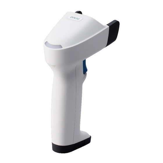
Chapter 1 Names and Functions Reading window A code is placed at this reading window. Indicator LED control Illuminates blue when reading is complete. (Refer to Section 8.2 for details.) Trigger switch Press this switch to start code reading. Beep hole The following trigger switch operating The beeper sounds when the scanner has read a modes are available. -
Page 12: Chapter 2 Preparation
For approx. 20 seconds after switching from the USB-COM interface to the USB keyboard interface, the scanner cannot accept data entry. * Registered users can download the configuration software (ScannerSetting_2D) from QBNet, their customer support section on the Denso Wave website at no extra charge. http://www.qbdirect.net... -
Page 13: Connecting The Interface Cable To The Scanner
2.2. Connecting the Interface Cable to the Scanner (1) Pull the connector cover of the interface cable off its connector as shown below. (2) Plug the interface cable connector into the connector located in the bottom of the scanner. Note: As shown below, hold the scanner body, align the ▼ mark on the cable connector with that on the Note: scanner, and fully insert the interface cable connector. -
Page 14: Chapter 3 Connection To The Host Computer
Chapter 3 Connection to the Host Computer 3.1 Using the RS-232C Interface (1) AC adaptor-powered type (a) Connect the RS-232C interface cable to the host computer. Scanner AC adapter DC jack RS-232C interface cable Serial port (b) Plug the AC adapter into the DC power jack provided in the RS-232C interface cable connector. Note: When disconnecting the interface cable or DC power jack, hold the connector housings not the cables. -
Page 15: Using The Usb Interface
3.2 Using the USB Interface The scanner receives and sends data from/to the host computer through the USB-COM interface or USB keyboard interface. You need to set up the device driver designed for the interface to be used (see 3.2.1 and 3.2.2). Notes for connecting the USB interface cable ... -
Page 16: Setting Up The Usb-Com Interface
3.2.1 Setting up the USB-COM interface Using the USB-COM interface requires installing the Active USB-COM port driver provided by DENSO WAVE to the host computer. The driver does not come with the scanner in a CD-ROM. It can be downloaded for free from our website at: http://www.qbdirect.net... -
Page 17: Setting Up The Usb Keyboard Interface
3.2.2 Setting Up the USB Keyboard Interface A USB class driver “HID (Human Interface Devices)” is used to communicate using the USB keyboard interface. This driver is included in the Windows system files. Note: If the scanner is set to the USB-COM interface, follow the procedures in Section 2.1 to switch to the USB keyboard interface. -
Page 18: Chapter 4 Scanning Codes
Chapter 4 Scanning Codes (1) Bring the reading window to the target code and press the trigger switch. The marker indicating the approximate center of the reading area irradiated by the illumination LEDs lights up for reading. (This step is not required for the Continuous reading modes 1, 2, Auto sensing mode and Auto stand mode.) Marker Working distance Illumination LEDs... -
Page 19: Chapter 5 Customizing The Scanner
RS-232C interface, USB-COM interface and USB keyboard interface. Note: The configuration software is not available via the USB keyboard interface. * Registered users can download the configuration software (ScannerSetting_2D) from QBNet, their customer support section on the Denso Wave website at no extra charge. http://www.qbdirect.net... -
Page 20: Chapter 6 Scanning Control
Chapter 6 Scanning Control Two types of scanning controls are available--Trigger switch control and Software control. Trigger switch control: Pressing the trigger switch readies the scanner for reading. (Refer to Section 6.1.) Software control: Instead of pressing the trigger switch, you send control commands from the host computer via the RS-232C or USB-COM interface to ready the scanner for reading or put the scanner on standby. -
Page 21: Software Control
6.2 Software Control You can control the scanner by sending scanning control commands from the host computer via the RS-232C or USB-COM interface, instead of pressing the trigger switch. Reading control commands are restricted by the trigger switch operating modes, as listed below. (For more information on control commands, see Appendix 2 Control Commands.) Trigger switch operating modes Commands... -
Page 22: Chapter 7 Scanning Functions
Chapter 7 Scanning Functions 7.1 Data verification mode The Data verification mode verifies the code data read against the master data stored in the scanner and reports the match status with data output. Data verification read is available in two types--“n-point verification” and “2-point verification,” which can be selected with the configuration software (ScannerSetting_2D). - Page 23 2-point Verification Scan master registration 1) Switch the scanner to the Data Verification mode and select the RS-232C or USB-COM interface. The indicator LED lights in green. 2) Use the scanner to scan a master code to be registered. (The scanner operates in the trigger switch operating mode currently set.) After registration of master data, the indicator LED turns blue and then goes OFF.
-
Page 24: Setting Data Subject To Verification
7.1.2 Setting Data Subject to Verification You can specify two types of verification objects--data string and data block. For data string verification, specify the verification start position and the number of characters to be verified. For data block verification, specify one of the data blocks delimited by commas in the CSV format. -
Page 25: Verification Result Output
7.1.3 Verification result output (1) Report of match/mismatch status You can select any of the following report types using the configuration software (ScannerSetting_2D). Selecting “Disable transmission” reports nothing. If there is a match: If there is a mismatch: Disabled Disabled Enable code data transmission. -
Page 26: Data Editing
7.2 Data Editing You can edit and output code data read, in any of the four data edit modes--“data extraction mode,” “data substitution mode,” “data blocksorting mode” and “ADF script mode.” These data edit modes can be selected with the configuration software (ScannerSetting_2D). - Page 27 Extraction start and end positions Start Position End Position First character nth position Last character nth position Last character By n positions from the start position nth position The n can be 1 through 9999. Note that if the extraction start position is specified as nth position, the extraction end position should be equal to or greater than the extraction start position.
-
Page 28: Data Block Extraction
7.2.1.2 Data Block Extraction If data read is in the comma-delimited CSV format, the scanner extracts data blocks specified by the data block numbers from a code specified by the “Code type” and then outputs it in the data transmission format selected in the scanner (see Section 9.4). - Page 29 Example: Code read: QR Code, Data: (See the table below.) Header: STX; Terminator: ETX; Scanner ID: Prohibited; Code mark: Prohibited; Number of digits: Prohibited; Prefix/Suffix : Not specified; BCC: Prohibited Extraction Setting options Scan Data Transmitted Data Block “Code type”: QR 1,23,456,7890 1 2 3 [STX]1[ETX][STX]23[ETX][STX]456[ETX]...
-
Page 30: Extracting Ai (Application Identifier)-Prefixed Strings
7.2.1.3 Extracting AI (Application Identifier)-prefixed strings If the scanner reads any of GS1-128, GS1 DataBar, and Composite (excluding linear components in GS1 Composite), it edits the data according to AI (Application ID) and outputs it in the data transmission format selected in the scanner (see Section 9.4). - Page 31 Tab (ASCII code 09H<HT>) Specifying a tab as delimiters outputs tab-delimited data. No tab follows the tail of the data. A header and terminator are added to the full string. None of a scanner ID, code ID mark, the number of digits, prefix, and suffix is added even if their transmissions are enabled.
- Page 32 (2) AI Parenthesis Mode In this mode, the scanner parenthesizes AIs contained in data read and outputs the edited data according to the extraction conditions. Setting options Item Options “Data transfer regardless of error Enabled/Disabled result” If the scanner fails to extract an AI-prefixed string when the “Data transfer regardless of error result” is permitted, it outputs the data read as is without editing.
- Page 33 (3) AI Table In the AI-prefixed string extraction, the scanner edits data according to the Application Identifiers (AIs) defined below. No. of Digits Description n2+n18 Serial Shipping Container Code (SSCC) n2+n14 Global Trade Item Number (GTIN) n2+n14 GTIN of Trade Items Contained in a logistic unit (For Use with AI 37 Only) n2+n14 Reserved area n2+n16...
- Page 34 No. of Digits Description 320n n4+n6 Net weight, pound (***) 321n n4+n6 Length or 1D size data, inch (***) 322n n4+n6 Length or 1D size data, feet (***) 323n n4+n6 Length or 1D size data, yard (***) 324n n4+n6 Width, diameter or 2D size data, inch (***) 325n n4+n6 Width, diameter or 2D size data, feet (***)
- Page 35 No. of Digits Description 352n n4+n6 Area, square yard (***) 353n n4+n6 Area, square inch, for distribution (***) 354n n4+n6 Area, square feet, for distribution (***) 355n n4+n6 Area, square yard, for distribution (***) 356n n4+n6 Net weight, troy, ounce (***) 357n n4+n6 Net weight (capacity) ounce (***)
- Page 36 No. of Digits Description n3+n13 EAN. UCC Global Location Number of the Invoicing Party n3+an..20 Postal code defined by specific postal facilities(ship-to address, location) n3+n3+an..9 Postal code stating with 3-digit ISO country code (ship-to address, location) n3+n3 Ship-to country of trade item n3+n15 Initial handling country n3+n3...
- Page 37 No. of Digits Description n2+an..30 FACT data identifier n2+an..30 Internal use – company Internal use – company n2+an..30 Internal use – company n2+an..30 Internal use – company n2+an..30 n2+an..30 Internal use - carrier n2+an..30 Internal use - carrier Internal use – company n2+an..30 Internal use –...
-
Page 38: Data Conversion Mode
7.2.2 Data Conversion Mode If the scanner reads a code specified by the “Code type” in this mode, it searches the data read for the specified string (max. 16 ASCII characters), substitutes it with the specified substitution string (max. 16 ASCII characters), and outputs it in the data transmission format selected in the scanner (see Section 9.4). -
Page 39: Blocksorting Mode
7.2.3 Blocksorting mode The scanner splits code data read into a maximum of 5 blocks at the specified split positions, sorts those blocks in the specified order, and outputs it in the data transmission format selected in the scanner (see Section 9.4). Note: The split position must be specified by the number of digits from the head of code data read. -
Page 40: Adf Script Mode
7.2.4 ADF script mode The ADF script refers to a simple program language designed for editing of data read. It enables the following functions. (1) Fixed/variable length data extraction (2) GS1-128, GS1 DataBar, GS1 Composite AI (Application Identifier) compatibility (3) Sorting data blocks into the specified order (4) Data verification. -
Page 41: Point Scan Mode
7.3 Point Scan Mode In the point scan mode, you can aim at a target code by matching up the marker with that code. If there is no code at the market or the scanner cannot detect the marker due to high levels of ambient lighting, the scanner cannot read anything. Make sure that the marker is actually pointing at the center of the code when scanning. -
Page 42: Scanning Structured Appended Qr (Iqr) Code Symbols
7.6 Scanning Structured Appended QR (iQR) Code Symbols QR Code symbology can split data into a maximum of 16 blocks and encode each of them into a Structured Appended QR Code symbol (model 1 or 2) or Structured Appended iRQ Code symbol. Structured Appended Code scanning is possible only with the same Code model. -
Page 43: Multi-Line Barcode Scanning
7.7 Multi-line Barcode Scanning The scanner can scan up to 3 lines of bar codes in the readable area at any one time. You can specify the number of lines to be scanned, the data output order and output format using the configuration software (ScannerSetting_2D). -
Page 44: Chapter 8 Beeper, Indicator Led, Marker, And Illumination Leds
Chapter 8 Beeper, Indicator LED, Marker, and Illumination LEDs 8.1 Beeper (1) Beeper The scanner emits a short or long beeps, once or a couple of times as described below. The beeper emits a short beep when: - the scanner has read a code successfully, - code data read matches the master data in the Data verification mode, - the scanner has read a Structured Appended QR (iQR) Code symbol, - the “Start setting”... - Page 45 (2) Beeper Volume Adjustment You can adjust the beeper volume to three levels--high, medium and low--using the QR-coded parameter menu or configuration software (ScannerSetting_2D). Each time the “Beeper volume” QR Code symbol is read, the beeper volume cycles as shown below. High Medium Even if the scanner is turned off, this setting will be retained.
-
Page 46: Indicator Led Control
8.2 Indicator LED control The indicator LED lights or flashes in blue, green, or red as described below. The indicator LED lights in blue when: - the scanner has read a code successfully, - the “Start setting” or “End setting” code is read from the QR-coded parameter menu (given in Chapter 12), - the scanner starts or ends a sequence of Structured Appended QR (iQR) Code scanning, - the scanner has read a Structured Appended QR (iQR) Code symbol, - the parameter values are saved by a PW command (refer to Appendix 2),... - Page 47 The indicator LED can be disabled with the QR-coded parameter menu or configuration software (ScannerSetting_2D). In any of the following cases, however, the indicator LED comes on regardless of the current LED setting. - when you make settings by scanning the QR-coded parameter menu, - When the scanner receives an LED-ON command (LB, LG or LR) from the host computer (refer to Appendix 2), - when the configuration software (ScannerSetting_2D) starts up or any setting you have made is established, - when the scanner reads a batch-process QR Code symbol, and...
-
Page 48: Marker
8.3 Marker The red marker LED lights up to indicate the approximate center of the reading area. The marker provides a choice of the three modes--normal marker mode, marker-OFF mode and marker-ON mode that can be selected by using the QR-coded parameter menu or the configuration software (ScannerSetting_2D). -
Page 49: Marker-Off Mode
8.3.2 Marker-OFF mode The marker LED will not come on under any conditions. 8.3.3 Marker-ON mode When the scanner switches to standby, the marker LED is turned on for approx. 30 seconds. When it is ready to scan, the marker LED remains on. 8.4 Illumination LEDs When the scanner is ready to scan, the illumination LEDs blink. -
Page 50: Chapter 9 Communication
Chapter 9 Communication 9.1 RS-232C Interface With the RS-232C interface being selected, the scanner uses asynchronous data transmission and communicates with the host computer or external equipment via the RS-232C. The communication level is RS-232C level. You can set various communications conditions using the QR-coded parameter menu or configuration software (ScannerSetting_2D). -
Page 51: Usb-Com Interface
It is, therefore, possible for applications capable of accepting keyed data to handle the data read by the scanner. Registered users can download the keyboard interface software (QR_kbif) from QBdirect, their customer support section on the Denso Wave website at no extra charge. http://www.qbdirect.net... - Page 52 Communication Protocol You can select either non-acknowledge mode or ACK/NAK mode. Non-acknowledge mode (default) If the CTS signal is at a high level (Enable transmission), the scanner transmits code data read. Note: The configuration software (ScannerSetting_2D) provides a choice of CTS timeout settings from 100 ms to 9.9 s in 100-ms increments and two CTS signal control choices Yes and No.
-
Page 53: Usb Keyboard Interface
9.3 USB Keyboard Interface The USB keyboard interface requires no dedicated device driver. Data read by the scanner can be entered to the cursor position in your application. The USB keyboard interface operates in conformity with the following: - Universal Serial Bus (USB) Device Class Definition for Human Interface Devices (HID) Version 1.11 - Universal Serial Bus (USB) HID Usage Tables Version 1.11 keyboard (1) CAPS Lock state Select the CAPS Lock ON or OFF to match the state of the connected keyboard. -
Page 54: Communication Format
9.4 Communication Format Regarding the data transmission format, select one of the following two data transmission formats. No. of Digits Scanner Code Header Prefix Code Data Suffix Terminator Mark No. of Digits Scanner Code Header Prefix Code Data Suffix Terminator Mark The following is the description of each item. - Page 55 (5) Code Mark This optional field specifies the code system. It offers ten combinations with five code ID marks (Type 1, Type 2, Type 3, Type 4, and user-defined) and two output modes (coupling and separating) as listed below. You can also select whether or not to transmit the code ID mark. (Default: No transmission) Code Mark Code Type Type1...
- Page 56 (1/2) Code Mark Code Type Type1 Type2 Coupling Separate Coupling Separate No Add-on Linear With two-digit Add-on EAN-13 Add-on None None Linear With five-digit Add-on Add-on None None No Add-on Linear With two-digit Add-on EAN-8 Add-on None None Linear With five-digit Add-on Add-on None...
- Page 57 Code Mark Code Type Type1 Type2 Coupling Separate Coupling Separate GS1 DataBar GS1 DataBar CC-A (Note 1) GS1 DataBar CC-B (Note 1) CC-A, CC-B None None (Note 2) (Note 2) No Add-on Linear With two-digit Add-on UPC-A Add-on None None None None UPC-A CC-A...
- Page 58 (2/2) Code Mark Code Type Type3 Type 4 (Note 3) Coupling Separate Coupling Separate QR Code Edit mode QR Code (Structured Batch edit mode Append mode) Unedit mode (Note 4) Micro QR Code (Note 4) SQRC (Note 4) iQR Code iQR Code Edit mode (Structured...
- Page 59 (2/2) Code Mark Code Type Type3 Type 4 (Note 3) Coupling Separate Coupling Separate Interleaved 2of5 Standard 2 of 5 (short) Standard 2 of 5 (normal) Code 39 Code 39 Full ASCII Codabar (NW-7) Code 128 GS1-128 Code 93 GS1 DataBar (Note 1) GS1 DataBar GS1 DataBar...
- Page 60 (Note 1) GS1 DataBar represents: GS1 DataBar Omnidirectional, GS1 DataBar Truncated, GS1 DataBar Limited, GS1 DataBar Stacked, GS1 DataBar Expanded, GS1 DataBar Stacked Omnidirectional, GS1 DataBar Expanded Stacked. (Note 2) These code ID marks are contained in code data. (Note 3) Type 4 is a code ID mark system compliant with the AIM USA “Guidelines on Symbology Identifiers.” The “m” suffix is a modifier character that differs depending upon options of individual symbologies as defined below.
- Page 61 (6) No. of Digits You can set whether or not to transmit the number of digits of the code data. The default is No transmission. When transmission is allowed, you can select 4 digits (4 bytes) or 2 digits (2 bytes). Note that UPC and EAN codes (except GS1-128) skip this field.
- Page 62 UPC-A You can select whether or not to transmit the padding character “0,” number system character “S,” and a check digit to the host. Disabling the transmission of the number system character “S” automatically disables the transmission of the padding character “0.”...
- Page 63 UPC-E with add-on A code ID mark precedes add-on code data under the conditions “Code ID mark: Type 4” and “Code ID mark output mode: Separating.” (For details about the code ID mark, refer to (5) Code ID mark) on p. 44 to 48. ) The conversion to the GTIN format or to the UPC-A are selectable.
- Page 64 EAN-13 with add-on A code ID mark precedes add-on code data under the conditions “Code ID mark: Type 4” and “Code ID mark output mode: Separating.” (For details about the code ID mark, refer to (5) Code ID mark) on p. 44 to 48. ) The conversion to the GTIN format is selectable.
- Page 65 Code 39 Code data read will be transmitted as is. You can select whether or not to transmit start/stop codes. Start/stop codes are “*”. Interleaved 2of5, Standard 2of5 The scanner transmits code data read, starting from the character following the start code to the one preceding the stop code. No start/stop codes will be transmitted.
-
Page 66: Gtin Format Conversion
9.5 GTIN format Conversion Enabling the GTIN (Global Trade Item Number) format conversion allows UPC-A, UPC-E, EAN-13, EAN-8, and Interleaved 2of5 (14-digit) data to output in the GTIN format. It also allows GS1 DataBar and GS1-128 data in the GTIN format to output in the product code (EAN-13/JAN-13) format. - Page 67 UPC-E - Data read 0: Padding character for adjustment of the data length - Conversion to 16-digit GTIN format (AI “01” and PI added) =0~2 0 1 PI 0 0 X 0 0 0 0 X 0 1 PI 0 0 X 0 0 0 0 0 X 0 1 PI 0 0 X 0 0 0 0 0 X...
- Page 68 EAN-13 - Data read : Prefix character - Conversion to 16-digit GTIN format (AI “01” and PI added) 0 1 PI P Check digits are calculated again and transferred regardless of the transmission specified. - Conversion to 14 digits. (Add “PI” to transfer.) PI P Check digits are calculated again and transferred regardless of the transmission specified.
- Page 69 EAN-8 with add-on - Data read With 2-digit add-on C/D X With 5-digit add-on C/D X : Prefix character : Add-on code data 6~10 - Conversion to 16-digit GTIN format (AI “01” and PI added) With 2-digit add-on 0 1 PI 0 0 0 0 0 P C/D X With 5-digit add-on 0 1 PI 0 0 0 0 0 P...
- Page 70 (2) Conversion from GS1 DataBar /GS1-128 in GTIN format to EAN/JAN format It is possible to select whether “conversion to EAN/JAN format” is required for GTIN format (16 digits for application identifier “01”) GS1 DataBar or GS1-128 scan data. The conversion provides two choices--13- or 14-digit EAN formats. The former trims the Application Identifier (AI) “01” and Package Indicator PI, and the latter, a PI only.
-
Page 71: Chapter 10 Image Capturing
Chapter 10 Image Capturing 10.1 Outline of the Function The scanner supports image capturing that allows you to capture a graphic as a bitmap (BMP) or JPEG image and output it to the host computer. The JPEG image offers three quality choices--standard, high, and low. The image size can be selected from standard VGA, 1/4 VGA and 1/16 VGA. - Page 72 m: Image size Standard VGA 1/4 VGA 1/16 VGA n: Image output area Full image area Center portion of the image area o: Thumbnail Disable thumbnail transmission 1 or null BMP thumbnail transmission 1/4 VGA JPEG thumbnail transmission (5) Operation 1) Upon receipt of an IMAGEOUT command, the scanner captures an image, beeps three times, and switches to the image transmission mode (Xmodem 1K protocol).
- Page 73 Image Type Output type Image File Size Transmission Time RS-232C USB-COM Standard VGA 307.2KB 15.5 sec 3.5 sec. 1/4 VGA 76.8KB 4.2 sec. 1.4 sec. 1/16 VGA 19.2KB 1.2 sec. 0.5 sec. Thumbnail (1/64 VGA) 4.8KB 0.5 sec. 0.3 sec. Thumbnail (1/4 VGA) JPEG 4.8KB...
-
Page 74: Chapter 11 Parameters And Defaults
Chapter 11 Parameters and Defaults You can set the parameters in the table below using the QR-coded parameter menu or configuration software (ScannerSetting_2D). The shadowed parameters, however, can be set with the configuration software only. When the scanner leaves the factory, all of these parameters are set to defaults. (1) Reading mode related parameters Setting Parameters... - Page 75 (3) Communications parameters for RS-232C interface The following settings take effect when the RS-232C interface is set up. Setting Parameters Default Setting Refer to: Non-acknowledge mode Communication Protocol Section 9.1 (1) ACK/NAK mode 4800 bps 9600 bps 19200 bps Transmission speed Section 9.1 (3) 38400 bps 57600 bps...
- Page 76 (5) Communications parameters for USB keyboard interface The following settings take effect only when the USB keyboard interface is set up. Setting Parameters Default Setting Refer to: Manual Section 9.3 (1) CAPS mode (Note 1) Auto CAPS LOCK OFF Section 9.3 (1) Host’s CAPS LOCK status (Note 1) CAPS LOCK ON...
- Page 77 Setting Parameters Default Setting Refer to: Enabled Special key transfer mode (Note 4) Disabled 10ms Data transmission interval 15ms Section 9.3 (5) 30ms 50ms 100ms Enabled Remote wake-up Section 9.3 (6) Disabled (Note 4) Special key transfer applies to the fields except header and terminator in the data transmission format. Enabling this function substitutes E7h to FDh data with the special keys as listed below and transmits the substituted data to the host.
- Page 78 (6) Data transmission format common to all interfaces Setting Parameters Default Setting Refer to: Enabled Transmission of code mark Section 9.4 Disabled Before Prefix Code mark position Section 9.4 After Prefix Type1 (DENSO1) Type2 (DENSO2) Code mark type Type3 Section 9.4 (5) Type4 User-defined Coupling...
- Page 79 (7) Data transmission format exclusive to RS-232C interface/USB-COM interface Setting Parameters Default Setting Refer to: None Header User-defined None Section 9.4 (1) Terminator CR LF User-defined Enabled Transmission of BCC Section 9.4 (4) Disabled : Can be changed only with the configuration software.
- Page 80 (8) Data transmission format exclusive to USB keyboard interface Setting Parameters Default Setting Refer to: None CR+LF Header ENTER Right Ctrl ← ↑ → ↓ User-defined Section 9.4 (1) None CR+LF Terminator ENTER Right Ctrl ← ↑ → ↓ User-defined : Can be changed only with the configuration software.
- Page 81 (9) 2D codes, mirror image, black-and-white inverted codes and SQRC Setting Parameters Default Setting Refer to: Enabled Reverse codes scanning Section 7.4 Disabled Black cells/bars on a white background Scanning a Black-and-white White cell/bars on a black background Section 7.5 Inverted Code Auto detection of black and white inverted codes...
- Page 82 Setting Parameters Default Setting Refer to: Enabled (SQRC and QR Code symbols) SQRC Scanning Enable SQRC scanning only Disabled Disabled Section 7.8 SQRC Encryption key mismatch Enable transmission of disclosed data only Enable transmission of disclosed data + undisclosed data SQRC Encryption key match Transmission of undisclosed data only SQRC Code minimum version...
- Page 83 (10) Bar codes UPC-A/E,EAN-13/8 Setting Parameters Default Setting Refer to: Enabled Scanning UPC-A and EAN-13 Sections 9.4 and 12.2 Disabled Enabled UPC-A transmission of check digit Disabled Enabled UPC-A Transmission of number system character Disabled Sections 9.4 and 12.2 Enabled UPC-A Transmission of the leading character Disabled...
- Page 84 Setting Parameters Default Setting Refer to: Enabled Reading EAN-8 Sections 9.4 and 12.2 Disabled Enabled EAN-8 transmission of check digit Disabled Enabled EAN-8 Conversion to the EAN-13 format Disable conversion Enabled Reading UPC/EAN with 2-digit add-on Disabled Sections 9.4 and 12.2 Enabled Reading UPC/EAN with 5-digit add-on...
- Page 85 Codabar(NW-7) Setting Parameters Default Setting Refer to: Enabled (without C/D) Enable, with a check digit (Check digit transmission enabled) Reading Codabar (NW-7) Section 12.2 Enable, with a check digit (Check digit transmission disabled) Disabled Minimum number of readable digits 4 digits for Codabar (NW-7) 3 to 99 digits (Note 1)
- Page 86 Code 128,GS1-128 Setting Parameters Default Setting Refer to: Enabled Reading Code 128 Disabled Section 12.2 (Note 2) Enabled Reading GS1-128 Disabled Minimum number of readable digits 1 digit 1 to 99 digits for Code 128 (Note 1) (excluding start/stop codes and 1-digit Maximum number of readable digits check digit) 99 digits...
- Page 87 GS1 DataBar,GS1 Composite Setting Parameters Default Setting Refer to: Enabled Reading GS1 DataBar Omnidirectional, GS1 DataBar Truncated Disabled Enabled Reading GS1 DataBar Stacked, GS1 DataBar Stacked Omnidirectional Disabled Enabled (ISO/IEC24724:2006) Reading GS1 DataBar Limited Enabled (ISO/IEC24724:2011) (Note 3) Disabled Enabled Reading GS1 DataBar Expanded Section 12.2 Disabled...
- Page 88 (Note 1) In the QR Code menu, the GS1 DataBar codes cannot separately be selected and they are enabled or disabled all together. They can be enabled or disabled separately with the configuration software. (Note 2) In the QR Code menu, the Composite codes cannot separately be selected and they are enabled or disabled all together.
- Page 89 Multi-line Barcode Scanning Selection Setting Parameters Default Setting Refer to: Enabled Multi-line Barcode Scanning Disabled 2 lines Number of readable lines for Multi-line barcode scanning 3 lines Header/terminator-delimited format Multi-line barcode output format Comma-delimited format 1st line barcode type Specified from enabled codes. Not specified Leading character for 1st line Up to 2 ASCII characters...
- Page 90 (11) TRIGGER SWITCH OPERATION Setting Parameters Default Setting Refer to: Auto off mode Momentary switching mode Momentary switching mode (Reverse Type) Section 6.1 Alternate switching mode TRIGGER SWITCH OPERATION Continuous reading mode 1 Continuous reading mode 2 Auto sense mode Section 6.3 Auto stand mode Auto-off mode reading time...
- Page 91 (12) Beeper, indicator LED, marker and illumination LEDs Setting Parameters Default Setting Refer to: Enabled Beeper control Disabled Low beeping tone (approx. 3.5 kHz) Beeper tone Medium beeping tone (approx. 3.8 kHz) High beeping tone (approx. 4.2 kHz) Short (60 ms) Section 8.1 Beeper beep time Medium (80 ms)
- Page 92 (13) Data verification conditions and data editing conditions Setting Parameters Default Setting Refer to: Data String Verification Data to be verified Data Block Verification Enabled Preset master registration Disabled Verification start position From 001 to 999 digits specify with for data string verification ASCII characters Number of characters to verify for data string verification...
- Page 93 Setting Parameters Default Setting Refer to: Search string and substitution string Max. 16 characters in ASCII characters Not specified in data substitution mode Number of splits in data blocksorting 2 to 5 splits 2 splits mode Split position in data blocksorting 0001 to 9999 characters in ASCII 1 character mode...
-
Page 94: Chapter 12 Qr-Coded Parameter Menu
Chapter 12 QR-Coded Parameter Menu 12.1 Parameter Setting Procedure Using the QR-coded Parameter Menu Use the scanner to scan the “Start setting” QR Code symbol. Start setting ↓Three beeps Scan necessary parameter setting QR Code symbols. Scan parameter setting QR Code symbols. ↓... -
Page 95: Qr-Coded Parameter Menu
12.2 QR-coded Parameter Menu ■ Menu control (Starting/Ending the Setting Procedure and Reverting to Defaults) Start setting Start setting Cancel All defaults End setting The beeper volume can be set by scanning the following QR Code symbol only. No “Start setting” or “End setting”... - Page 96 ■ Communications parameters for RS-232C interface Communication Protocol Non-acknowledge mode ACK/NAK mode (default) Transmission speed 4800 bps 9600 bps 19200 bps 38400 bps (default) 57600 bps 115200 bps Word length 7 bits 8 bits (default)
- Page 97 Parity None (default) Even parity Odd parity Stop bit 1 bit (default) 2 bits ■ USB interface to the host USB-COM interface (default) USB Keyboard Interface...
- Page 98 ■ Communications parameters for USB-COM interface Communications protocol (USB-COM interface) Non-acknowledge mode ACK/NAK mode (default) Header (USB-COM interface) None (default) Terminator (USB-COM interface) None CR LF Transmission of BCC (USB-COM interface) Disable (default) Enabled...
- Page 99 ■ Communications parameters for USB keyboard interface Binary Data Conversion No conversion (default) (ASCII) Binary conversion Kanji conversion Header (USB keyboard interface) None (default) CR+LF ENTER Right Ctrl...
- Page 100 Header (USB keyboard interface) ← ↑ → ↓ Terminator (USB keyboard interface) None CR LF ENTER (default) Right Ctrl...
- Page 101 Terminator (USB keyboard interface) ← ↑ → ↓ ■ Communication Format Transmission of code ID mark Disable (default) Enable Transmission of the number of digits Disable (default) Enable in 2 digits Enabled, in 4 digits...
- Page 102 ■ 2D codes, mirror image and black-and-white inverted codes Reading MicroQR Disabled Enable (default) Scanning a Black-and-white Inverted Code Black cells/bars on a White cells/bars on white background (default) a black background Automatically identify black and white inverted codes Scanning Structured Appended QR (iQR) Code Unedit mode <Edit mode>...
- Page 103 Reading MaxiCode Disabled Enable (default) Scanning Data Matrix Disabled Enable (default) ■ Bar codes Scanning UPC-A, UPC-E, EAN-13 and EAN-8 Disabled Enable (default) Reading Interleaved 2 of 5 Enable with a check digit Disabled (Check digit transmission disabled) Enable without a check digit (default) Enable with a check digit (Check digit transmission enabled)
- Page 104 Scanning Code 128 (GS1-128) Disable Enable (default) Scanning Codabar (NW-7) Disable Enable without a check digit (default) Enable with a check digit Enable with a check digit (Check digit transmission enabled) (Check digit transmission disabled) Transmission of start/stop codes for Codabar (NW-7) Disabled Enable (default) Reading Code 39...
- Page 105 Transmission of Start/Stop codes for Code 39 Disable (default) Enable Reading Code 93 Disable (default) Enable Scanning GS1 DataBar Disable (default) Enable Scanning Composite Disable (default) Enable...
- Page 106 ■ Other settings TRIGGER SWITCH OPERATION Auto-off mode (default) Alternate switching mode Momentary switching mode Momentary switching mode (Reverse type) Continuous reading mode 1 Continuous reading mode 2 Auto sensing mode Auto stand mode Beeper control Disable Enable (default) Indicator LED control Disable Enable (default)
-
Page 107: Chapter 13 Troubleshooting
Chapter 13 Troubleshooting Problem 1: Low reading efficiency. Probable cause What to do: A target code is not within the reading area of the Bring a code within the reading area. reading window. The code may be smeared. Wipe off the dirt from the code. The code may be blurred. -
Page 108: Appendix 1 Specifications
Weight Approx. 125 g (excluding the cable) (∗1) To use SQRC (Security QR Code), contact your Denso Wave representative. (∗2) Applied to QR Codes and Data Matrix. (∗3) Sharp temperature change, dewing or freezing not allowed, wet-bulb temperature 30℃ max. -
Page 109: Appendix 2 Control Commands
Appendix 2 Control Commands Control commands refer to commands that are exchanged between the host computer and the scanner via the communications line. Some of the control commands that the host computer issues are functionally equivalent to some parameters that can be set with the QR-coded parameter menu (refer to Chapter 11). - Page 110 Direction Description Control Commands Scanner Host TRIGGER SWITCH OPERATION Auto off mode Momentary switching mode Alternate switching mode Continuous reading mode 1 Continuous reading mode 2 Auto sense mode Auto stand mode Momentary switching mode (Reverse type) Parameter storage This command saves settings made with U1 through U8 commands (Note 5) into the EEPROM.
- Page 111 Direction Description Control Commands Scanner Host Mismatch If code data scanned does not match master data in Data verification mode, the scanner sends this command as long as the NG transmission is enabled for a mismatch. DEFAULT The parameter setting is reset to the default setting (factory default). (Note 1) If the scanner receives the R command twice with the reading window being applied to a code (for example, it receives the R command, sends the code data read, and receives the Z and R commands), it will send even the same code data twice.
- Page 112 Commands which consist of the command section + option section Direction Description Command Scanner Host 1D Code Scanning Code Setting 2D Code Scanning Code Setting Note 1) The setting is not changed when the above commands only are transmitted. (1) S command’s option section format Specified readable code Specified check digit Specified max.
- Page 113 Specify the scanning code with symbol, check digit with symbol of a relevant code, and Min. and Max. number of digits with symbol + number of digits (in single or double digits). The setting range must be from the minimum number of digits to maximum number of digits.
-
Page 114: Appendix 3 Interface Specifications
Appendix 3 Interface Specifications ■ RS-232C Interface Dsub 9pin ,socket type Power supplied Power supplied from AC adapter from host Pin No. Terminal Name N.C. N.C. 6 and short circuit N.C. 4 and short circuit N.C. (Viewed from pin side) N.C. - Page 115 ■ USB Interface Type A USB connector (Viewed from pin side) Pin No. Terminal Name 5 V DC...
- Page 116 2D code handy scanner AT30Q-SM AT31Q-SM Manual September 2016 First Edition DENSO WAVE INCORPORATED AUTO-ID Business Unit...
- Page 117 1 Yoshiike, Kusagi, Agui-chō, Chita-gun, Aichi 470-2297, JAPAN http://www.denso-wave.com/...