GE KTD-405 User Manual
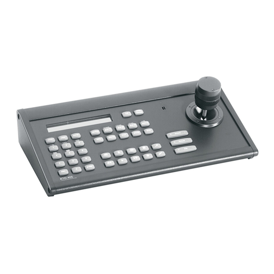
Controller keypad
Hide thumbs
Also See for KTD-405:
- User manual (76 pages) ,
- User manual (76 pages) ,
- Quick manual (16 pages)
Table of Contents
Advertisement
Quick Links
Advertisement
Table of Contents
Troubleshooting

Related Manuals for GE KTD-405


Summary of Contents for GE KTD-405
-
Page 1: User Manual
Security KTD-405/KTD-405A Controller Keypad User Manual imagination at work... - Page 2 Document number/revision: 1036547D. Disclaimer The information in this document is subject to change without notice. GE, in keeping pace with technological advances, is a company of product innovation. Therefore, it is difficult to ensure that all information provided is entirely accurate and up-to-date. GE accepts no...
-
Page 3: Table Of Contents
KTD-405 overview........ - Page 4 Troubleshooting your KTD-405 keypad ........
-
Page 5: Chapter 1 Ktd-405 Overview
KTD-405 overview This chapter provides an explanation of the conventions in this document and an overview of your KTD-405 keypad. In this chapter: Introduction..........2 Product overview . -
Page 6: Introduction
KTD-405 Keypad User Manual Introduction This is the GE KTD-405 Keypad User Manual for models KTD-405 and KTD-405A. This document includes an overview of the product and detailed instructions explaining: • how to install a KTD-405 keypad; and • how to program and operate a KTD-405 keypad. -
Page 7: Product Overview
Product contents The KTD-405 (Figure 1) and KTD-405A (Figure 2) packages, in addition to the items shown, include this KTD-405 Keypad User Manual (1036547) and a quick reference guide (1047307). Figure 1. KTD-405 package contents... -
Page 8: Operating Modes
KTD-405 Keypad User Manual Operating modes The KTD-405 can be programmed to operate in two modes: standard Digiplex or zone (DVMR/multiplexer/ ® PTZ control). (See Appendix A, Sample configurations and charts for layout samples of these modes.) Note: Be aware that the addressing between domes and multiplexers is offset. When setting up and controlling your cameras... -
Page 9: Zone Mode
System controller mode is an extension of standard and hybrid Digiplex modes, a mode that allows use of the KTD-405 with the HDS (High Density Switch) system controller. In this type of system, each user is assigned a user number that determines the user’s access privileges for each of the system resources. Users must log on to the keypad using their assigned user number. - Page 10 KTD-405 Keypad User Manual...
-
Page 11: Chapter 2 Installation
Chapter 2 Installation This chapter shows all the connections you’ll need to make to get your KTD-405 keypad and all the peripheral devices working within a diverse video surveillance network. In this chapter: Installation guidelines........8 Back panel connections . -
Page 12: Installation Guidelines
• Your system should contain only one RS-422 chain of devices. Only one KTD-405 keypad should be in that chain, which can contain any number of other RS-422-only keypads such as KTD-404s. -
Page 13: Back Panel Connections
KTD-405 connections Adhere to all installation guidelines while making connections, including your local codes and those provided Installation guidelines on page 8. Figure 6. KTD-405 back panel connections RS-232 programming port (future use) RJ45 control cable (GE equipment I/O box uses two different RJ45 cables. -
Page 14: Ktd-405A Connections
Figure 7. KTD-405A back panel connections RS-232 programming port (future use) RJ11 audio cable I/O box Audio port RJ45 control cable (GE equipment Power supply uses two different RJ45 cables. You RS-485 and RS-422 in/out Power cord must use the RJ45 cable provided RS-485 termination switch with the unit.) -
Page 15: I/O Box Connections
Multiplexer or DVMRe RS-485 (optional RJ45 connection*) For DVMRes, multiplexers, 1 2 3 4 5 6 7 8 ProBridges, and additional KTD-405 I/O boxes. RS-485 (optional RJ45 RS- 485 connection*) For DVMRes, multiplexers, ProBridges, and additional KTD-405 I/O boxes. EARTH GROUND... -
Page 16: Twisted-Pair Connections
KTD-405 Keypad User Manual Twisted-pair connections The twisted-pair connections are available to connect additional devices or for existing installations where individual wires were used to connect to the old phone-style I/O box. Easy-to-use RJ-cable connections are also available on the new I/O box. See RJ-cable connections on page 11. -
Page 17: Connecting A Multiplexer Or Dvmre And Domes
Adhere to all installation guidelines while making connections, including your local codes and those provided Installation guidelines on page 8. Figure 10. Connecting a keypad (KTD-405 shown) to a multiplexer or DVMRe (shown) and domes 1 2 3 4 5 6 7 8 EARTH GROUND... -
Page 18: Connecting Multiple Keypads With Rj45 Cables
Connecting multiple keypads with RJ45 cables Adhere to all installation guidelines while making connections, including your local codes and those provided Installation guidelines on page 8. Figure 11. KTD-405 and KTD-405A connections via RJ45 cables Observe polarity for: • audio • RS-422 •... -
Page 19: Connecting Multiple Keypads With Stp Cable
Connecting multiple keypads with STP cable Adhere to all installation guidelines while making connections, including your local codes and those provided Installation guidelines on page 8 Figure 12. KTD-405 and KTD-405A connections via STP cables Observe polarity for: • audio • RS-422 •... -
Page 20: Connecting New And Old I/O Boxes
KTD-405 Keypad User Manual Connecting new and old I/O boxes Adhere to all installation guidelines while making connections, including your local codes and those provided Installation guidelines on page 8. Note: For additional connection details about the old I/O boxes, see Appendix D. Old I/O Box Connections. -
Page 21: Chapter 3 Programming
Chapter 3 Programming This chapter explains the programming modes and goes through the various steps you’ll need to follow to program your keypad. In this chapter: Programming modes........18 User programming . -
Page 22: Programming Modes
KTD-405 Keypad User Manual Programming modes There are different programming modes for the keypad: • User programming mode: Establishes the keypad’s system architecture for operations. • Remote device programming mode: Lets you program system devices such as cameras and VCRs. -
Page 23: Entering Programming Modes
Chapter 3 Programming Entering programming modes To enter programming mode, do the following: 1. When you provide power to the unit, the Figure 15. Normal operating display normal operating display appears (Figure 15). CAMERA 0 MONITOR 1 2. Press and hold the key until you hear a Figure 16. -
Page 24: User Programming
KTD-405 Keypad User Manual User programming As explained in Entering programming modes on page 19, to enter the user menus, from the ENTER PROGRAMMING CODE menu, press 5-7-9-seq. This brings up the OPERATING MODE menu (Figure 17). Figure 17. OPERATING MODE menu... - Page 25 Chapter 3 Programming 6. The following access menus (Figure 19) are Figure 19. Access menus used to restrict the keypad from addressing specified sites in the system. CAMERA 000 ACCESS? The access menus enable you to allow (+)=YES (-)=NO NEXT access for each camera, monitor, DSR/ VCR, and multiplexer.
- Page 26 KTD-405 Keypad User Manual 12. By default, the selected monitor number Figure 22. MONITOR OFFSET display corresponds to the number of the matrix switcher output to which it is connected. For MONITOR OFFSET example, if monitor 12 appears in the...
-
Page 27: Zone Menus
Chapter 3 Programming Zone menus Remember that the addressing between domes and multiplexers is offset. When setting up and controlling your cameras in zone mode, refer to Zone receiver site addressing on page 53). To program your keypad in zone mode, do the following: 1. - Page 28 KTD-405 Keypad User Manual 6. The next display mentions zone hubs Figure 29. Zone hub display (Figure 29). A hub is the main recording device in a zone. Hub choices are DVMRE ZONE 01 HUB: DVMRE DUP DUP, CALIBUR MMX, TRIPLEX MUX,...
- Page 29 Chapter 3 Programming 11. The annunciation menu (Figure 34) is for Figure 34. Annunciation menu future use. When annunciation is enabled, the keypad displays the first, second, and ANNUNCIATION? third call-in/alarm on thee LCD and stores up (+)=YES (-)=NO NEXT to 32 call-in requests.
-
Page 30: Remote Programming
KTD-405 Keypad User Manual Remote programming At the ENTER PROGRAMMING CODE menu, press 9-5-1-seq to display the REMOTE PROGRAMMING menu, which allows you to program devices such as cameras and VCRs, as shown in the tree in Figure 37. Figure 37. Remote programming menu tree... -
Page 31: Cyberscout Shadow Tours
Chapter 3 Programming CyberScout shadow tours This section explains how to program CyberScout shadow tours. Note: Refer to the CyberDome Programming Manual for the programming of CyberDome tours. To program a CyberScout ShadowTour™, do the following: 1. Beginning at the normal operating display, Figure 38. - Page 32 KTD-405 Keypad User Manual...
-
Page 33: Chapter 4 Operation
Chapter 4 Operation This chapter explains how to operate your KTD-405 keypad. It also describes the different operating modes, standard Digiplex mode and zone mode. In this chapter: Operating your keypad ........30 Standard Digiplex mode . -
Page 34: Operating Your Keypad
3 Stop. flip aux 4 Last for KTD-405; talk for KTD-405A. stabilize Activates a sequence tour on the active monitor (Calibur multiplexers only). function alarm Toggles active monitor between the alarm on and alarm off modes; calls up help menus when remotely programming matrix switcher and CyberDome. - Page 35 Chapter 4 Operation Table 3. Normal and shifted key functions (continued) Normal function Shifted function Toggles selected multiplexer’s full-screen picture between normal and 2X magnification. light Locates video on selected DVMRe. 0 lux Places selected DSR, VCR, or DVMRe in pause mode. joystick up Places selected DSR, VCR, or DVMRe in play mode.
-
Page 36: Standard Digiplex Mode
KTD-405 Keypad User Manual Standard Digiplex mode When you provide power to the unit, the normal operating display appears (Figure 41), showing the current camera number and the current monitor number. Figure 41. Normal operating display CAMERA 0 MONITOR 1... -
Page 37: Setting Autopan Limits
Chapter 4 Operation Setting autopan limits You can set the left and right autopan limits separately. Left autopan limit To set the limit for the left turn-around point of the camera’s back and forth motion, as wells as the tilt and zoom positions for the autopan, do the following: 1. -
Page 38: Operating Group Switching On Digiplex Iv Switchers
KTD-405 Keypad User Manual Operating group switching on Digiplex IV switchers To operate a group, do the following: 1. In Digiplex mode, hold esc and press zone to Figure 44. Enter monitor group menu display the ENTER MONITOR GROUP menu (Figure 44). -
Page 39: Controlling A Dvmre/Multiplexer
Chapter 4 Operation Controlling a DVMRe/multiplexer When you press the zone key, the keypad switches to the hybrid zone mode. In this mode, the keypad can control a DVMRe/multiplexer. Key functions are the same as those used during normal zone mode operation, except the esc key, which returns the keypad to the standard Digiplex mode. -
Page 40: Zone Mode
KTD-405 Keypad User Manual Zone mode The LCD displays the zone number and title on the top line and the current camera and monitor numbers on the bottom line (Figure 46). Figure 46. Zone mode main menu ZONE -- ZONE TITLE... - Page 41 Chapter 4 Operation Selecting and controlling a DVMRe/multiplexer When a zone is active, the corresponding DVMRe/multiplexer can be controlled by the keypad (Table 5). Table 5. Controlling a multiplexer Control Function for multiplexer Function for DVMRe starts record mode starts record mode starts playback mode (if multiplexer has an attached starts playback mode DSR/VCR, a play command is sent to the multiplexer...
- Page 42 KTD-405 Keypad User Manual 4. Enter the Calibur address. 5. Press 6. Enter the Calibur password. To navigate the DVMRe/multiplexer programming menus, see Table 6. Table 6. Navigating Calibur menu Control Function Joystick moves left and right within menu options; can be used to move up and down within the menu options makes selections backspaces out of selections;...
-
Page 43: Programming A Dvmre/Multiplexer Camera Sequence
Chapter 4 Operation Programming a DVMRe/multiplexer camera sequence If you are using a Calibur DVMRe/multiplexer, set a camera sequence by doing the following: 1. Press store. 2. Press seq. to display the ENTER Figure 47. Enter sequence menu SEQUENCE menu (Figure 47). 3. - Page 44 KTD-405 Keypad User Manual Two-way audio To establish two-way audio communication with a site: 1. Press 0 through 9 to enter a site number. 2. Use the vol (volume) keys to adjust the audio level. 3. Press aux 4 to talk to the site. The aux 4 key on the audio-version of the keypad automatically defaults to talk mode.
-
Page 45: Chapter 5 Troubleshooting, Maintenance, Support
Troubleshooting, maintenance, support This section provides information to help you diagnose and solve various problems that may arise while configuring or using your GE Security product and offers technical support contacts in case you need assistance. In this chapter: Troubleshooting your KTD-405 keypad . -
Page 46: Troubleshooting Your Ktd-405 Keypad
The keypad may be positioned incorrectly on the RS-422 control line with a switcher and data merger. Refer to the keypad, switcher, and data merger installation instructions and correct wiring along RS-422 control line. With the KTD-405 keypad, the units should be in line in the following order: keypad, data merger, and switcher. -
Page 47: Contacting Technical Support
Many GE Security documents are provided as PDFs (portable document format). To read these documents, you will need Adobe Acrobat Reader, which can be downloaded free from Adobe’s website at www.adobe.com. - Page 48 KTD-405 Keypad User Manual...
-
Page 49: Appendix A. Sample Configurations And Charts
Appendix A Sample configurations and charts This appendix provides several sample configuration diagrams to help you visualize your system and also includes DIP switch aids, charts, and other helpful information. In this appendix: Sample system configurations....... . . 46 Old I/O box connections . -
Page 50: Sample System Configurations
KTD-405 Keypad User Manual Sample system configurations Figure 50. Typical KTD-450 Digiplex configuration EARTH GROUND EARTH GROUND RS485 RS485 RS422 IN RS422 IN RS422 OUT RS422 OUT SPEAKER SHIELD SPEAKER SHIELD SPEAKER SPEAKER Video RS-422 RS-485 Keypads (with I/O boxes) - Page 51 Appendix A Sample configurations and charts Figure 51. Typical KTD-450A Digiplex configuration Video ZONE 32 PARKING GARAGE auto CAMERA 22 MONITOR 2 focus last view zone dsr/vcr aux 1 aux 2 aux 3 aux 4 EARTH GROUND RS-422 RS485 alarm tour store find...
- Page 52 KTD-405 Keypad User Manual Figure 52. HDS hybrid configuration Crosspoint 32 EARTH GROUND EARTH GROUND RS485 RS485 RS422 IN RS422 IN RS422 OUT RS422 OUT SPEAKER SHIELD SPEAKER SHIELD SPEAKER SPEAKER ZONE 32 PARKING GARAGE ZONE 32 PARKING GARAGE auto...
- Page 53 Appendix A Sample configurations and charts Figure 53. Zone configuration EARTH GROUND EARTH GROUND RS485 RS485 RS422 IN RS422 IN RS422 OUT RS422 OUT SPEAKER SHIELD SPEAKER SHIELD SPEAKER SPEAKER Video RS-422 ZONE 32 PARKING GARAGE auto ZONE 32 PARKING GARAGE focus auto CAMERA 22...
-
Page 54: Old I/O Box Connections
KTD-405 Keypad User Manual Old I/O box connections Figure 54. Old I/O box connections for audio and nonaudio keypads BR G G BK Nonaudio I/O box Audio I/O box Data connections RS-485 A RS-422 out B RS-485 B RS-422 out A... - Page 55 Appendix A Sample configurations and charts Figure 55. Connecting a multiplexer or DVMRe to the old I/O box Connect PIN 3 to RS-485 A (RD) To multiplexer or DVMRe (ground at RS-422 output (to CyberDomes/PTZ mux/DVMRe) receivers Connect PIN 6 to RS-485 B (BK) Floating shield RS-422 input (if used) Connect PIN 1 to RS-485 shield...
-
Page 56: Connecting Multiple Keypads To The Old I/O Box
12 VDC in (no polarity) To additional keypads or multiplexer/ RS-422 output (to CyberDomes) DVMRe (ground at mux/DVMRe) To/from KTD-405 12 VDC in (no polarity) Figure 57. KTD-405 to KTD-405A connections BR G G BK Audio connections Shield (float) RS-422 input (from alarm chassis) -
Page 57: Zone Receiver Site Addressing
Appendix A Sample configurations and charts Zone receiver site addressing Each receiver has a DIP switch used to assign its site address. In zone operation, to determine the receiver site address, see Table 9, Table 10, and Figure 58 on page 53 and perform the following: 1. - Page 58 KTD-405 Keypad User Manual Table 10. Receiver site addressing values by zone Zone number Camera input...
-
Page 59: Reprogrammable Keys And Commands
Appendix A Sample configurations and charts Reprogrammable keys and commands Figure 59. Keys that can be reprogrammed ZONE 32 CAMERA 22 Recommended set Complete set Table 11. Commands that can be assigned to reprogrammed keys ALARM FIND LOCK STEP FIRST MACRO STEP FWD (for future use) -
Page 60: System Planning Chart
KTD-405 Keypad User Manual System planning chart Make photocopies of this table to help you plan your system.