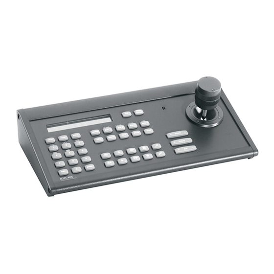
GE KTD-405 User Manual
Controller keypad
Hide thumbs
Also See for KTD-405:
- User manual (76 pages) ,
- User manual (60 pages) ,
- Quick manual (16 pages)
Table of Contents
Advertisement
Quick Links
Advertisement
Table of Contents
Troubleshooting

Related Manuals for GE KTD-405


Summary of Contents for GE KTD-405
-
Page 1: User Manual
KTD-405/KTD-405A/KTD-405-2D Controller Keypad User Manual... - Page 2 Document number/revision: 1036547G. Disclaimer The information in this document is subject to change without notice. GE, in keeping pace with technological advances, is a company of product innovation. Therefore, it is difficult to ensure that all information provided is entirely accurate and up-to-date. GE accepts no...
-
Page 3: Table Of Contents
KTD-405/405A/405-2D overview........ - Page 4 KTD-405/KTD-405A/KTD-405-2D Controller Keypad User Manual Chapter 4. Operation ............. 37 Operating your keypad .
-
Page 5: Preface
Preface This is the GE KTD-405/KTD-405A/KTD-405-2D Controller Keypad User Manual. This document includes an overview of the product and detailed instructions explaining: • how to install a KTD 405/KTD-405A/KTD-405-2D keypad; and • how to program and operate a KTD-405/KTD-405A/KTD-405-2D keypad. - Page 6 KTD-405/KTD-405A/KTD-405-2D Controller Keypad User Manual...
-
Page 7: Chapter 1 Ktd-405/405A/405-2D Overview
Chapter 1 KTD-405/405A/405-2D overview This chapter provides an explanation of the conventions in this document and an overview of your keypad. In this chapter: Product overview ......... . . 4 Operating modes. -
Page 8: Product Overview
The KTD-405 (Figure 1) and KTD-405A (Figure 2) packages, in addition to the items shown, include this KTD-405/KTD-405A/KTD-405-2D Controller Keypad User Manual (1036547) and a quick reference guide (1047307). The KTD-405-2D (not shown) is similar to the KTD-405, but with a 2-axis joystick instead of a 3- axis joystick. -
Page 9: Operating Modes
Chapter 1 KTD-405/405A/405-2D overview Operating modes The KTD-405 can be programmed to operate in two modes: standard Digiplex or zone (DVMR/multiplexer/ ® PTZ control). (See Appendix A, Sample configurations and charts for layout samples of these modes.) Note: Be aware that the addressing between domes and multiplexers is offset. When setting up and controlling your cameras in... -
Page 10: Zone Mode
KTD-405/KTD-405A/KTD-405-2D Controller Keypad User Manual Zone mode A zone is a remote switching device (multiplexer or DVMRe) that serves a group of cameras. A system can be divided into as many as 32 independent zones, and each zone can have from 1 to 64 cameras (average Zone size is 32, only Matrix switcher supports 64 and is less commonly used) depending on the type of controlling device. -
Page 11: Chapter 2 Installation
Chapter 2 Installation This chapter shows all the connections you’ll need to make to get your keypad and all the peripheral devices working within a diverse video surveillance network. In this chapter: Installation guidelines........8 Back panel connections . -
Page 12: Installation Guidelines
• The installation of the KTD-405 is designed to work at the head end of a RS422 Digiplex or a RS485 GE/Impac system, so care should be taken to keep only one RS485 network and one RS422 network in a large system. - Page 13 Chapter 2 Installation Note: The keypads ship with an updated I/O box that provides RJ45 ports for the RS-485 data line and an RJ11 port for audio. Connecting new and old I/O boxes on page 17 for connections between the new and old I/O boxes. For connection details for the old I/O boxes, see Old I/O box connections on page 61.
-
Page 14: Back Panel Connections
KTD-405/KTD-405-2D connections Adhere to all installation guidelines while making connections, including your local codes and those provided Installation guidelines on page 8. Figure 5. KTD-405/KTD-405-2D back panel connections RS-232 programming port (future use) RJ45 control cable (GE equipment I/O box uses two different RJ45 cables. -
Page 15: Ktd-405A Connections
Figure 6. KTD-405A back panel connections RS-232 programming port (future use) RJ11 audio cable I/O box Audio port RJ45 control cable (GE equipment Power supply uses two different RJ45 cables. You RS-485 and RS-422 in/out Power cord must use the RJ45 cable provided RS-485 termination switch with the unit.) -
Page 16: I/O Box Connections
KTD-405/KTD-405A/KTD-405-2D Controller Keypad User Manual I/O box connections RJ-cable connections The RJ-cable connections make new installations or additional devices easy to connect. If you are replacing an old phone-style I/O box in an existing installation, you can use the existing twisted-pair wires (STP for RS-485 and UTP for RS-422), if desired. -
Page 17: Twisted-Pair Connections
Chapter 2 Installation Twisted-pair connections The twisted-pair connections are available to connect additional devices or for existing installations where individual wires were used to connect to the old phone-style I/O box. Easy-to-use RJ-cable connections are also available on the new I/O box. See RJ-cable connections on page 12. -
Page 18: Connecting A Multiplexer Or Dvmre And Domes
Adhere to all installation guidelines while making connections, including your local codes and those provided Installation guidelines on page 8. Figure 9. Connecting a keypad (KTD-405 shown) to a multiplexer or DVMRe (shown) and domes 1 2 3 4 5 6 7 8 EARTH GROUND... -
Page 19: Connecting Multiple Keypads With Rj45 Cables
Connecting multiple keypads with RJ45 cables Adhere to all installation guidelines while making connections, including your local codes and those provided Installation guidelines on page 8. Figure 10. KTD-405, KTD-405-2D, and KTD-405A connections via RJ45 cables Observe polarity for: • audio • RS-422 •... -
Page 20: Connecting Multiple Keypads With Stp Cable
Connecting multiple keypads with STP cable Adhere to all installation guidelines while making connections, including your local codes and those provided Installation guidelines on page 8 Figure 11. KTD-405 and KTD-405A connections via STP cables Observe polarity for: • audio • RS-422 •... -
Page 21: Connecting New And Old I/O Boxes
Chapter 2 Installation Connecting new and old I/O boxes Adhere to all installation guidelines while making connections, including your local codes and those provided Installation guidelines on page 8. Note: For additional connection details about the old I/O boxes, see Appendix D. Old I/O Box Connections. Figure 12. -
Page 22: Setting Audio Attenuation
KTD-405/KTD-405A/KTD-405-2D Controller Keypad User Manual Setting audio attenuation When using a KTD-336 audio converter, set the attenuation jumpers to the ON position (Figure 13). The attenuation jumpers are located on the audio/IO card, which is attached to the keypad’s base plate. When not using an audio converter, leave the attenuation jumpers in their default OFF position. -
Page 23: Chapter 3 Programming
Chapter 3 Programming This chapter explains the programming modes and goes through the various steps you’ll need to follow to program your keypad. In this chapter: Programming modes........20 Supervisor programming . -
Page 24: Programming Modes
KTD-405/KTD-405A/KTD-405-2D Controller Keypad User Manual Programming modes There are different programming modes for the keypad: • Supervisor programming mode: Establishes such essentials as the keypad’s nonvolatile memory, title and many fundamental operating parameters, and allows flexible system setup. • User programming mode: Establishes the keypad’s system architecture for operations. -
Page 25: Entering Programming Modes
Chapter 3 Programming Entering programming modes To enter programming mode, do the following: 1. When you provide power to the unit, the Figure 15. Normal operating display normal operating display appears (Figure 15). CAMERA 0 MONITOR 1 2. Press and hold the key until you hear a Figure 16. -
Page 26: Supervisor Programming
Figure 27 on page 26 of this menu. This is a critical number since it is needed to change any of the access codes. Be sure to store the new number in a safe place. If the number is lost, GE Security technical support can help you reset the keypad to factory defaults. - Page 27 In most cases this menu setting will remain at the default KB3 PTZ PROTOCOL? value of NO. However, if the KTD-405 you are using in a system that needs to communicate PTZ commands to a Calibur CBR-KB3/J keypad or ProBridge, you may need to select YES so that the KTD-405 communicates properly with these devices.
- Page 28 KTD-405/KTD-405A/KTD-405-2D Controller Keypad User Manual 6. The keypad lockout priority menu Figure 21. KEYPAD LOCKOUT PRIORITY displays (Figure 21) allows the supervisor to set up a hierarchical relationship amoung keypads in KEYPAD LOCKOUT the system so that keypads with a higher...
- Page 29 Chapter 3 Programming Entering a new preset number or pressing will take you to the display shown in Figure 23. 8. To change key assignments, press the + side Figure 23. PROGRAM SOFT KEYS display of the zoom, focus, or iris keys. PROGRAM SOFT KEYS? 9.
- Page 30 KTD-405/KTD-405A/KTD-405-2D Controller Keypad User Manual 14. Press esc to exit to the PROGRAM SOFT KEYS display. 15. Pressing or the side of the zoom, focus, Figure 27. CHANGE ACCESS CODES displays or iris key takes you to the CHANGE ACCESS CODES display (Figure 27). If you...
- Page 31 Chapter 3 Programming 17. Pressing or entering a baud rate value Figure 29. SYSTEM CONTROL display takes you to the SYSTEM CONTROLLER display (Figure 29). A System Controller is SYSTEM CONTROLLER? used with the HDS (High Density Switch) (+)=YES (-)=NO system to provide more comprehensive control of larger systems.
-
Page 32: User Programming
KTD-405/KTD-405A/KTD-405-2D Controller Keypad User Manual User programming As explained in Entering programming modes on page 21, to enter the user menus, from the ENTER PROGRAMMING CODE menu, press 5-7-9-seq. This brings up the OPERATING MODE menu (Figure 31). Figure 31. OPERATING MODE menu... - Page 33 Chapter 3 Programming 6. The following access menus (Figure 33) are Figure 33. Access menus used to restrict the keypad from addressing specified sites in the system. CAMERA 000 ACCESS? The access menus enable you to allow access for each camera, monitor, DSR/VCR, and multiplexer.
- Page 34 KTD-405/KTD-405A/KTD-405-2D Controller Keypad User Manual 12. By default, the selected monitor number Figure 36. MONITOR OFFSET display corresponds to the number of the matrix switcher output to which it is connected. For MONITOR OFFSET example, if monitor 12 appears in the NUMBER: 0 NEXT keypad’s display window and a camera...
-
Page 35: Zone Menus
Chapter 3 Programming Zone menus Remember that the addressing between domes and multiplexers is offset. When setting up and controlling your cameras in zone mode, refer to Receiver site addressing on page 65). To program your keypad in zone mode, do the following: 1. - Page 36 KTD-405/KTD-405A/KTD-405-2D Controller Keypad User Manual 6. The next display mentions zone hubs Figure 43. Zone hub display (Figure 43). A hub is the main controlling device in a zone. Hub choices are DVMRE ZONE 01 HUB: DUP, CALIBUR MMX, TRIPLEX MUX,...
- Page 37 Chapter 3 Programming 11. The annunciation menu (Figure 48) is for Figure 48. Annunciation menu future use. When annunciation is enabled, the keypad displays the first, second, and ANNUNCIATION? third call-in/alarm on thee LCD and stores up to 32 call-in requests. 12.
-
Page 38: Remote Programming
KTD-405/KTD-405A/KTD-405-2D Controller Keypad User Manual Remote programming At the ENTER PROGRAMMING CODE menu, press 9-5-1-seq to display the REMOTE PROGRAMMING menu, which allows you to program devices such as cameras and VCRs, as shown in the tree in Figure 51. -
Page 39: Quick Shadow Tour 1 Programming Short Cut
Chapter 3 Programming Quick Shadow Tour 1 programming short cut This section explains how to use the shadow tour 1 programming shortcut. To program a ShadowTour™, do the following: 1. Beginning at the normal operating display, Figure 52. Normal operating display bring up the PROGRAM SHADOW TOUR display (Figure 52) by pressing and holding CAMERA 0... - Page 40 KTD-405/KTD-405A/KTD-405-2D Controller Keypad User Manual...
-
Page 41: Chapter 4 Operation
Chapter 4 Operation This chapter explains how to operate your keypad. It also describes the different operating modes, standard Digiplex mode and zone mode. In this chapter: Operating your keypad ........38 Standard Digiplex mode . -
Page 42: Operating Your Keypad
KTD-405/KTD-405A/KTD-405-2D Controller Keypad User Manual Operating your keypad Table 3 shows the default functions for the keypad’s keys in normal and shifted mode (shaded cells). To select the shifted mode, press and hold esc and then press the key. Some keys can be changed to other functions. - Page 43 Chapter 4 Operation Table 3. Normal and shifted key functions (continued) Function store With number keys, sets presets and autopan limits for selected camera; accesses sequence programming for Calibur multiplexers. Group. Activates group switching and group sequence initiation. find With number keys, selects PTZ position saved by the previous store command for selected camera site. Step +zoom - Controls the zoom function on selected receiver site’s motorized zoom lens.
- Page 44 KTD-405/KTD-405A/KTD-405-2D Controller Keypad User Manual Table 3. Normal and shifted key functions (continued) Function Places selected monitor’s DSR, VCR, or DVMRe in stop mode; esc plus exits play mode in multiplexers. Live. Key for DVMRe live mode selection. Places selected DSR, VCR, or DVMRe in record mode.
-
Page 45: Standard Digiplex Mode
Chapter 4 Operation Standard Digiplex mode When you provide power to the unit, the normal operating display appears (Figure 55), showing the current camera number and the current monitor number. Figure 55. Normal operating display CAMERA 0 MONITOR 1 Selecting a monitor There are two ways to enter the number for a new monitor: 1. -
Page 46: Controlling A Camera
Note: Each GE PTZ has it's own limitations for Presets, but the 405 keypad supports 1-127 plus Calling Home which is preset 0 for CyberDome 2. Also please see each PTZs user manual for more details. -
Page 47: Recalling A Preset
Chapter 4 Operation user would realize the error. The keypad will prompt for the final store press, and give a confirmation message that it was actually stored. If the preset number is not in the allowed range, the keypad will give an error message instead of asking for the final press of the store key. -
Page 48: Setting Autopan Limits
KTD-405/KTD-405A/KTD-405-2D Controller Keypad User Manual Setting autopan limits You can set the left and right autopan limits separately. Left autopan limit To set the limit for the left turn-around point of the camera’s back and forth motion, as wells as the tilt and zoom positions for the autopan, do the following: 1. -
Page 49: Controlling A Recording Device
Chapter 4 Operation Controlling a recording device When a recording device is selected, it can be controlled by the keypad. (See Table 4, Controlling a recording device Receiver site addressing on page 65 for details.) Table 4. Controlling a recording device Control Function for DSR/VCR Function for DVMRe and SymDecs... -
Page 50: System Information Menus
KTD-405/KTD-405A/KTD-405-2D Controller Keypad User Manual System information menus In standard Digiplex mode, holding mon at the normal operating menu displays three system information menus. These menus show the keypad’s address, version, and system size setting. Use to navigate through these menus. To exit the system information menus, press from the first menu or press esc. -
Page 51: Audio
Chapter 4 Operation Audio Annunciation and alarms When a keypad is programmed for site annunciation, it stacks as many as 32 call-in requests in the order in which they are received. The numbers of the first three sites appear in the keypad’s display window (Figure 60). -
Page 52: Zone Mode
KTD-405/KTD-405A/KTD-405-2D Controller Keypad User Manual Zone mode The LCD displays the zone number and title on the top line and the current camera and monitor numbers on the bottom line (Figure 61). Figure 61. Zone mode main menu ZONE --ZONE TITLE CAMERA --MONITOR To select a zone, press zone and enter the zone number. - Page 53 Chapter 4 Operation Selecting and controlling a DVMRe/multiplexer When a zone is active, the corresponding DVMRe/multiplexer can be controlled by the keypad (Table 5). Table 5. Controlling a multiplexer Control Function for multiplexer Function for DVMRe starts record mode starts record mode starts playback mode (if multiplexer has an attached starts playback mode DSR/VCR, a play command is sent to the multiplexer...
- Page 54 KTD-405/KTD-405A/KTD-405-2D Controller Keypad User Manual To enter a Calibur DVMRe/multiplexer’s programming menus, do the following: 1. Enter the remote programming mode: a. Press and hold b. Press 9-5-1-seq. 2. Select 1, switcher/multiplexer. 3. Select 2, Calibur. 4. Enter the Calibur address.
-
Page 55: Programming A Dvmre/Multiplexer Camera Sequence
Chapter 4 Operation Programming a DVMRe/multiplexer camera sequence If you are using a Calibur DVMRe/multiplexer, set a camera sequence by doing the following: 1. Press store. 2. Press seq. to display the ENTER Figure 62. Enter sequence menu SEQUENCE menu (Figure 62). 3. - Page 56 KTD-405/KTD-405A/KTD-405-2D Controller Keypad User Manual...
-
Page 57: Chapter 5 Troubleshooting And Support
Chapter 5 Troubleshooting and support This section provides information to help you diagnose and solve various problems that may arise while configuring or using your GE Security product and offers technical support contacts in case you need assistance. In this chapter: Troubleshooting your keypad . -
Page 58: Troubleshooting Your Keypad
The keypad may be positioned incorrectly on the RS-422 control line with a switcher and data merger. Refer to the keypad, switcher, and data merger installation instructions and correct wiring along RS-422 control line. With the KTD-405 keypad, the units should be in line in the following order: keypad, data merger, and switcher. - Page 59 Chapter 5 Troubleshooting and support • I cannot accurately program a shadow tour using RS-485 or ASCII protocols while using KTD-405-2D. While recording shadow tours, RS-422 and ASCII protocols cannot communicate nor record all camera commands while the pan/tilt joystick and zoom buttons are used simultaneously. Use zoom commands...
-
Page 60: Contacting Us
Application. Select the appropriate product category for the contact information or use the dropdown menu to select a location outside the US. Many GE documents are provided as PDFs (portable document format). To read these documents, you will need Adobe Reader, which can be downloaded free from Adobe’s website at www.adobe.com. -
Page 61: Appendix A. Sample Configurations And Charts
Appendix A Sample configurations and charts This appendix provides several sample configuration diagrams to help you visualize your system and also includes DIP switch aids, charts, and other helpful information. In this appendix: Sample analog system configurations......58 Sample IP system configuration . -
Page 62: Sample Analog System Configurations
KTD-405/KTD-405A/KTD-405-2D Controller Keypad User Manual Sample analog system configurations Figure 63. Typical KTD-405/KTD-405-2D Digiplex configuration EARTH GROUND EARTH GROUND RS485 RS485 RS422 IN RS422 IN RS422 OUT RS422 OUT SPEAKER SHIELD SPEAKER SHIELD SPEAKER SPEAKER Video RS-422 RS-485 Keypads (with I/O boxes) - Page 63 Appendix A Sample configurations and charts Figure 64. Typical KTD-450A Digiplex configuration Video ZONE 32 PARKING GARAGE auto CAMERA 22 MONITOR 2 focus last view zone dsr/vcr aux 1 aux 2 aux 3 aux 4 EARTH GROUND RS-422 RS485 alarm tour store find...
- Page 64 KTD-405/KTD-405A/KTD-405-2D Controller Keypad User Manual Figure 65. Zone configuration EARTH GROUND EARTH GROUND RS485 RS485 RS422 IN RS422 IN RS422 OUT RS422 OUT SPEAKER SHIELD SPEAKER SHIELD SPEAKER SPEAKER Video RS-485 ZONE 32 PARKING GARAGE auto ZONE 32 PARKING GARAGE...
-
Page 65: Old I/O Box Connections
Appendix A Sample configurations and charts Old I/O box connections Figure 66. Old I/O box connections for audio and nonaudio keypads BR G G BK Nonaudio I/O box Audio I/O box Data connections RS-485 A RS-422 out B RS-485 B RS-422 out A 12 VDC in (no polarity) RS-422 in B... - Page 66 KTD-405/KTD-405A/KTD-405-2D Controller Keypad User Manual Figure 67. Connecting a multiplexer or DVMRe to the old I/O box Connect PIN 3 to RS-485 A (RD) To multiplexer or DVMRe (ground at RS-422 output (to CyberDomes/PTZ mux/DVMRe) receivers Connect PIN 6 to RS-485 B (BK)
-
Page 67: Connecting Multiple Keypads To The Old I/O Box
12 VDC in (no polarity) To additional keypads or multiplexer/ RS-422 output (to CyberDomes) DVMRe (ground at mux/DVMRe) To/from KTD-405 12 VDC in (no polarity) Figure 69. KTD-405/KTD-405-2D to KTD-405A connections BR G G BK Audio connections Shield (float) RS-422 input (from alarm chassis) -
Page 68: Sample Ip System Configuration
PTZ device. Figure 70 is an example of a SymDec single-zone system configuration. Note: All GE IP dome’s addresses are always one number lower than the physical input number on the SymDec 16 plus 4. Figure 70. SymDec 16 plus 4 single-zone system configuration... -
Page 69: Receiver Site Addressing
Appendix A Sample configurations and charts Receiver site addressing Each receiver has a DIP switch used to assign its site address. To determine the receiver site address, see Table 8, Table 9, and Figure 71 on page 65 and perform the following: 1. - Page 70 KTD-405/KTD-405A/KTD-405-2D Controller Keypad User Manual Table 9. Receiver site addressing values by zone Zone number Camera input...
-
Page 71: Reprogrammable Keys And Commands
Appendix A Sample configurations and charts Reprogrammable keys and commands From the supervisor programming mode you can reprogram any of the soft keys with any of the available commands. Note: Holding the seq key for three seconds returns you to the normal operating display, except on displays where esc is required to exit. - Page 72 KTD-405/KTD-405A/KTD-405-2D Controller Keypad User Manual Table 10. Commands that can be assigned to reprogrammed keys ALARM FIND LOCK STEP FIRST MACRO STEP FWD (for future use) AUTO FCS FLIP MAGNIFY STEP REV AUTO PAN GROUP OPEN STOP RCD BADGE HOME...
-
Page 73: System Planning Chart
Appendix A Sample configurations and charts System planning chart Make photocopies of this table to help you plan your system. - Page 74 KTD-405/KTD-405A/KTD-405-2D Controller Keypad User Manual...
-
Page 75: Index
Index access code....................26 key assignments ..................25 annunciation................30, 33, 47 keypad operation..................38 audio......................47 audio attenuation..................18 autopan limits..................44 monitor selection................41, 48 multiple keypads connections..............63 multiplexer control................44, 49 back panel connections ................10 baud rate....................26 operating mode ..................5 Digiplex ....................5 zone.......................6 camera control...................42, 48 camera selection................41, 48 connections back panel...................10... - Page 76 KTD-405/KTD-405A/KTD-405-2D Controller Keypad User Manual technical support ..................56 zone mode ...................6, 48 technical support centers.................56 troubleshooting ..................53...