Rangemaster Professional+ 100 FX User's Manual & Installation Instructions
Dual fuel
Hide thumbs
Also See for Professional+ 100 FX:
- User's manual & installation instructions (36 pages) ,
- User's manual & installation instructions (36 pages) ,
- User's manual & installation instructions (48 pages)

Related Manuals for Rangemaster Professional+ 100 FX


Summary of Contents for Rangemaster Professional+ 100 FX
-
Page 1: User Guide
Britain’s No.1 Range Cooker USER GUIDE & INSTALLATION INSTRUCTIONS Professional+ 100 FX Dual Fuel... - Page 2 We o er cookware to work perfectly with all fuel types manufactured by Rangemaster, including induction hobs. You can be assured of functionality with style, as well as the quality and meticulous attention to detail you expect from the pioneers of range cooking.
-
Page 3: Table Of Contents
Contents Before You Start... Troubleshooting Important! Installation Installation and Maintenance Dear Installer Peculiar Smells Safety Requirements and Regulations If You Smell Gas Provision of Ventilation Ventilation Location of Cooker Personal Safety Conversion Cooker Care Positioning the Cooker Cleaning Moving the Cooker Cooker Overview Completing the Move Hotplate Burners... -
Page 5: Before You Start
1. Before You Start... If You Smell Gas Your cooker should give you many years of trouble-free cooking if installed and operated correctly. It is important • DO nOT turn electric switches on or off that you read this section before you start, particularly if you •... -
Page 6: Cooker Care
Danger of fire: DO NOT store items on the cooking never leave the hotplate unattended at high heat settings. surfaces. Pans boiling over can cause smoking, and greasy spills may catch on fire. Use a deep fat thermometer whenever possible To avoid overheating, DO NOT install the cooker to prevent fat overheating beyond the smoking point. -
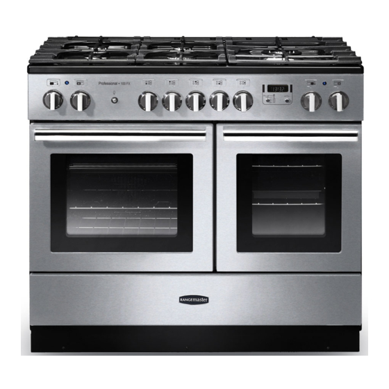
Page 7: Cooker Overview
2. Cooker Overview DocNo.020-0006 - Overview - 100DF - Prof+ Fig.2-1 Professional + 100 FX ArtNo.270-0029 - Prof+ 90SC annotated The 100 dual fuel cooker (Fig.2-1) has the following features: Fig.2-2 ArtNo.270-0001 5 hotplate burners including a wok burner Proplus control to high A control panel incorporting a timer Main multi-function oven Multi-function oven... -
Page 8: Wok Burner
If, when you let go of the control knob, the burner goes out, Fig.2-3 then the FSD has not been bypassed. Turn the control knob ArtNo.270-0003 to the ‘OFF’ position and wait for one minute before you try Proplus control to low again, this time making sure to hold in the control knob for slightly longer. -
Page 9: The Wok Cradle
The Wok Cradle Fig.2-9 The wok cradle is designed to t a 35 cm wok. If you use a di erent wok, make sure that it ts the cradle. Woks vary very widely in size and shape. It is important that the wok sits down on the pan support –... -
Page 10: The Multi-Function Ovens
The Multi-function Ovens Function Both ovens are multi-function ovens. In addition to the To thaw small items in the oven without Defrost element around the fan, it is tted with extra heating heat elements, in the top of the oven and under the oven base. A full cooking function, even heat Fan oven Take care to avoid touching the top elements when placing... -
Page 11: The Ovens
are ideal for cooking in this way, as the circulated air reduces Right-hand Multi-function Oven Modes the erceness of the heat from the grill. The oven door should Table 2-2 gives a summary of the right-hand multi-function be kept closed while cooking is in progress, so saving energy. modes. -
Page 12: The Clock
Operating the Ovens Fig.2-15 Turn the oven knob to the desired temperature (Fig.2-15). The oven indicator light will glow until the oven has reached the temperature selected (Fig.2-15). It will then cycle on and ArtNo.270-0026 o during cooking. Proplus MF oven controls (2) The Clock You can use the clock to turn the left-hand oven on and o . -
Page 13: Manual Cooking
] position (Fig.2-21). Turn the Timer knob to the [ Fig.2-21 ArtNo.301-0009 2BC Setting the cooking timer Turn the Adjusting knob to set the ‘cooking time’ you need (Fig.2-22). Turn the Timer knob to the [ ] position. The display will show the current time of day plus the ‘cook time’... -
Page 14: Accessories
Accessories Fig.2-28 Oven Shelves – Left-hand (Main) Oven The left-hand oven is supplied with two at shelves (Fig.2-28). The oven shelves are retained when pulled forward but can be easily removed and re tted. To re t the shelf, line up the shelf with a groove in the oven shelf supports and push the shelf back until the ends hit the shelf stop. -
Page 15: Cooking Tips
3. Cooking Tips Cooking with a Multi-function Oven General Oven Tips Remember: not all modes are suitable for all food types. The The wire shelves should always be pushed rmly to the back oven cooking times given are intended for a guide only. of the oven. -
Page 16: Cooking Table
4. Cooking Table DocNo.031-0004 - Cooking table - electric & fan single cavity The oven control settings and cooking times given in the table below are intended to be used AS Top (T) A GUIDE ONLY. Individual tastes may require the temperature to be altered to provide a preferred ArtNo.050-0007 result. -
Page 17: Cleaning Your Cooker
5. Cleaning Your Cooker Essential Information Fig.5-1 Isolate the electricity supply before carrying out any thorough cleaning. Allow the cooker to cool. NEVER use paint solvents, washing soda, caustic cleaners, biological powders, bleach, chlorine based bleach cleaners, coarse abrasives or salt. DO NOT mix di erent cleaning products –... -
Page 18: Control Panel And Doors
Control Panel and Doors Fig.5-5 Avoid using any abrasive cleaners including cream cleaners. For best results, use a liquid detergent. The same cleaner can be used on the doors, or alternatively, using a soft cloth wrung out in clean hot soapy water – but take care that no surplus water seeps into the appliance. -
Page 19: Removing The Right-Hand Oven Cover Plate And Reflector Tray
Removing the Right-hand Oven Shelf Supports Fig.5-9 To clean the oven sides, slide out the shelves, unhook the shelf supports from the oven sides (Fig.5-9), and lift out. Re t in reverse, making sure that the bottom of the shelf supports are inserted into the holes at the bottom of the oven (Fig.5-10), prior to hooking the top into position. -
Page 20: Cleaning Table
Cleaning Table Cleaners listed (Table 5-1) are available from supermarkets or electrical retailers as stated. For enamelled surfaces use a cleaner that is approved for use on vitreous enamel. Regular cleaning is recommended. For easier cleaning, wipe up any spillages immediately. Hotplate Part Finish... -
Page 21: Troubleshooting
6. Troubleshooting Hotplate ignition or hotplate burners faulty If there is an installation problem and I don’t get my original installer to come back to fix it who pays? Is the power on? Is the clock illuminated? You do. Service organisations will charge for their call If not, there maybe something wrong with the power outs if they are correcting work carried out by your supply. - Page 22 The timed oven is not coming on when automatic cooking Fig.6-1 Has the oven knob been left in the OFF position by mistake? Is the oven locked (see above)? ArtNo.324-0005 Oven light bulb Oven temperature getting hotter as the cooker gets older If turning the temperature down using the oven control knob has not worked, or has only worked for a short time, then you may need a new thermostat.
-
Page 23: Installation
INSTALLATION Check the appliance is electrically safe and gas sound when you have nished. 7. Installation Dear Installer In the UK the cooker must be installed in accordance with: Before you start your installation, please complete the details below, so that, if your customer has a problem relating to •... -
Page 24: Location Of Cooker
INSTALLATION Check the appliance is electrically safe and gas sound when you have nished. Checking the Parts: Location of Cooker The cooker may be installed in a kitchen/kitchen diner but 3 pan supports Griddle NOT in a room containing a bath or shower. This appliance is designed for domestic cooking only. -
Page 25: Positioning The Cooker
INSTALLATION Check the appliance is electrically safe and gas sound when you have nished. Positioning the Cooker Fig.7-1 Fig.7-1 shows the minimum recommended distance from the cooker to nearby surfaces. 75 mm 75 mm 650 mm The cooker should not be placed on a base. Above hotplate surround should be level with, or above, any adjacent work surface. -
Page 26: Completing The Move
INSTALLATION Check the appliance is electrically safe and gas sound when you have nished. Lowering the Two Rear Rollers Fig.7-4 To adjust the height of the rear of the cooker, rst t a 13 mm spanner or socket wrench onto the hexagonal adjusting nut (Fig.7-4). -
Page 27: Conversion To Another Gas
INSTALLATION Check the appliance is electrically safe and gas sound when you have nished. Conversion to Another Gas Fig.7-9 Outer stability If the appliance is to be converted to another gas do the bracket conversion at this point. See the conversion section of these instructions and see the instructions in the conversion kit. -
Page 28: Electrical Connection
INSTALLATION Check the appliance is electrically safe and gas sound when you have nished. Pressure Testing Fig.7-11 The gas pressure can be measured at one of the hotplate burner injectors (not the wok burner). Lift o a burner head. Fit the pressure gauge to the injector. Turn on and light one of the other hotplate burners. -
Page 29: Final Checks
INSTALLATION Check the appliance is electrically safe and gas sound when you have nished. Final Checks Fig.7-13 Hotplate Check Check each burner in turn (refer to the ‘Hotplate Burners’ section at the front of the instructions). Oven Check Set the clock as described earlier in the instructions, and then turn on the ovens. -
Page 30: Circuit Diagram
8. Circuit Diagram P028728 P057681 The connections shown in the circuit diagram are for single-phase. The ratings are for 230 V 50 Hz. Code Description Code Description Code Colour Left-hand oven multi-function switch Right-hand oven top element (inner) Blue Left-hand oven multi-function oven Right-hand oven base element Brown thermostat... -
Page 31: Technical Data
9. Technical Data ArtNo.105-0008 - Technical data - 90 induction - Elan THE COOKER IS CATEGORY: Cat II 2H3+ . It is supplied set for group H natural gas. A conversion kit from NG to LP is packed with the cooker. INSTALLER: Please leave these instructions with the User. - Page 32 Notes...
- Page 33 Notes...
- Page 34 Notes...
- Page 35 Gas Safe registered engineer for gas appliances or an approved electrician for electrical models. CONSUMER SERVICE For a competitive quote and to arrange for a Rangemaster approved If you have any product enquiries, or in the event of a problem engineer to attend, call Consumer Services on: 0870 7895107.
- Page 36 Registered in England and Wales. Registration No. 354715 Registered O ce: Juno Drive, Leamington Spa, Warwickshire, CV31 3RG Rangemaster continuously seeks improvements in speci cation, design and production of products and thus, alterations take place periodically. Whilst every e ort is made to produce up-to-date literature, this booklet should not be regarded as an infallible guide to...