
Related Manuals for LG WM2901H*A Series


Summary of Contents for LG WM2901H*A Series
- Page 1 Website:http://biz.lgservice.com WASHING MACHINE SERVICE MANUAL CAUTION READ THIS MANUAL CAREFULLY TO DIAGNOSE PROBLEMS CORRECTLY BEFORE SERVICING THE UNIT. MODEL: WM2901H*A...
- Page 2 APRIL. 2009 PRINTED IN KOREA P/No.:MFL30599137...
-
Page 5: Table Of Contents
CONTENTS Specifications ..........................5 Features & Technical Explanation ....................6-8 Parts Identification ........................... 9 Installation & Test ........................10-12 Operation ..........................13-19 5-1. Control Panel Features ..................... 13-15 5-2. Cycle Guide ........................... 16 5-3. Special Functions ........................17 5-4. Explanation of Each Process .................... 18-19 Wiring Diagram / Program Chart .................... -
Page 6: Specifications
1. SPECIFICATIONS ITEM WM2901H*A COLOR W:BLUE WHITE, R:WILD CHERRY, L:PACIFIC BULE POWER SUPPLY AC 120 V, 60 Hz PRODUCT WEIGHT 220.5 lbs (100kg) WASHING 280 W ELECTRIC POWER DRAIN MOTOR 80 W CONSUMPTION WASH HEATER 1000 W WASH REVOLUTION 46 rpm... -
Page 7: Features & Technical Explanation
2. FEATURES & TECHNICAL EXPLANATION 2-1. FEATURES Ultra Capacity The Larger drum enables not just higher head drop and stronger centrifugal force, but also less tangling and wrinkling of the laundry. Heavier loads, such as king size comforters, blankets, and curtains, can be washed. Direct Drive System The advanced Brushless DC motor directly drives the drum without belt and pulley. -
Page 8: Water Level Control
2-2. NEURO FUZZY WASHING TIME OPTIMIZATION To get the best washing performance, optimal time is determined by the water temperature, the selected washing temperature, and the size of the load. water temperature washing time the best selected NEURO- washing rinsing time washing FUZZY temperature... -
Page 9: Child Lock
2-5. THE DOOR CAN NOT BE OPENED While program is operating. When a power failed and power plug is taken out in operation. While Door Lock lights turn on. White the motor is in the process of intertial rotating, through the operation is paused. 2-6. -
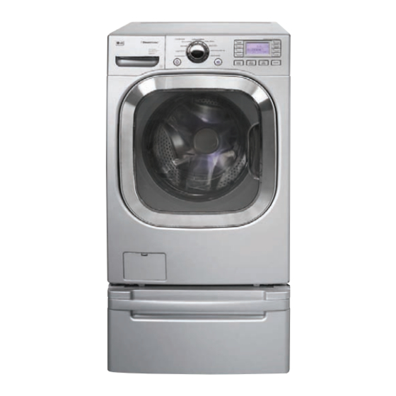
Page 10: Parts Identification
3. PARTS IDENTIFICATION Shipping Blots Power Plug • If the supply cord is damaged, it must be replaced by the manufacturer or its authorized service Drain Hose technician in order to avoid a hazard. Dispenser Control Panel Water Circulation & Steam Nozzle Door Drum Light... -
Page 11: Installation & Test
4. INSTALLATION & TEST Before servicing, ask the customer what the trouble is. Check the setup (power supply is 120 V AC, remove the transit bolts level the washer...,). Check with the troubleshooting guide. Plan your service method by referring to the disassembly instructions. Service the unit. -
Page 12: How To Connect The Inlet Hose
HOW TO CONNECT THE INLET HOSE Cold Verify that the rubber washer is inside of the valve connector. Tighten the inlet hose securely to prevent leaks. Install the inlet hose to correct temperature water tap. Otherwise, it cause drips on the drawer panel handle and drawer panel. - Page 13 7 TEST OPERATION Preparation for Press the POWER button. Press the Start/Pause button. washing. • Connect the power plug to the outlet. • Listen for a click to determine if the • Connect the inlet hoses. door has locked. Check the water heating Check the automatic reverse Check the water supply.
-
Page 14: Operation
5. OPERATION 5-1. CONTROL PANEL FEATURES WM2801H*A... - Page 15 Power Button Status Indicator • Use this button to turn the power • It shows elapsed time of the cycle the washer is operating. On/Off. Cycle Selector Knob Start/Pause • Rotate the Cycle selector knob to select the cycle designed •...
-
Page 16: Option Button
Option Button • STEAM: Use the STEAM button to add steam to the cycle for the extra cleaning. • WASH/RINSE OPTIMIZER: Use the WASH/RINSE OPTIMIZER button to select the water level, and detergent mount automatically by the smart sensor & program. •... -
Page 17: Cycle Guide
5-2. Cycle Guide The cycle guide below shows the options and recommended fabric types for each cycle. Wash/Rinse Pre- Rinse + Extra Stain Water Quick Wash/ Rinse Cycle Fabric Type Spin Speed Soil Level Steam Temp. Wash Spin Rinse Cycle Plus Cycle Optimizer... -
Page 18: Special Functions
5-3. SPECIAL FUNCTIONS The option buttons also activate special functions, including CHILD LOCK, DRUM LIGHT, TUB CLEAN, and LANGUAGE. Press and hold the option button marked with the special function for 3 seconds to activate. CHILD LOCK Use this option to prevent unwanted use of the washer or to keep cycle settings from being changed while the washer is operating. -
Page 19: Explanation Of Each Process
5-4. Explanation of each process Process Explanation Stay • Electrical power is supplied. • Washer is ready to work and the micom is in the active mode. Water • After loading laundry and selecting a course and a cycle, water is supply supplied and drum rotates. - Page 20 Process Explanation Intermittent • To reach the correct set speed, the motor rotates clockwise and spin counterclockwise directions after spin process starts. • If the water level frequency is lower than 23.0 kHz, a washer senses suds and starts suds removal process. Rinse •...
-
Page 21: Wiring Diagram / Program Chart
6. WIRING DIAGRAM / PROGRAM CHART... -
Page 23: Test Mode
7. TEST MODE 7-1. SAFETY CAUTION There’s built-in AC 120V and DC power in output terminal of PWB assembly in common. Be careful electric shock when disconnecting parts while trouble shooting. (Wear Electro Static Discharge gloves when working.) After cutting off the power when changing PWB assembly, disconnect or assemble. Be careful static when handling PWB assembly, and use Electro Static Discharge plastic pack when delivering or keeping it. -
Page 24: Troubleshooting
8. TROUBLESHOOTING 8-1. SAFETY CAUTION There’s built-in AC 120V and DC power in output terminal of PWB assembly in common. Be careful electric shock when disconnecting parts while trouble shooting. (Wear Electro Static Discharge gloves when working.) After cutting off the power when changing PWB assembly, disconnect or assemble. Be careful static when handling PWB assembly, and use Electro Static Discharge plastic pack when delivering or keeping it. - Page 25 ERROR SYMPTOM CAUSE • The connector (3-pin, male, white) in the MOTOR LOCKED MOTOR HARNESS is not connected to the connector (3-pin, ERROR female, white) of STATOR ASSEMBLY. • The electric contact between the connectors (3-pin, male, white) in the MOTOR HARNESS and 4-pin, female, white connector in the MAIN PWB ASSEMBLY is bad or unstable.
-
Page 26: Troubleshooting Summary
8-3. TROUBLESHOOTING SUMMARY... -
Page 27: Troubleshooting With Error
8-4. TROUBLESHOOTING WITH ERROR INLET VALVE ERROR Replace the Is the voltage of the inlet INLET VALVE valve connector 120 V AC? ASSEMBLY. (Check the all terminal of INLET VALVE ASSEMBLY displayed? while the power is on.) Check the AIR When you press both CHAMBER WASH/RINSE button and... -
Page 28: Drain Error
DRAIN ERROR Is the coil of the drain Replace the pump too high or low? DRAIN PUMP (resistance of the coil ASSEMBLY. is 10-20Ω) displayed? (Refer to 9-4 Pump motor assembly.) Reconnect or Is the connector connected Replace the Is the voltage between repair to pump motor assembly MAIN PWB... - Page 29 HEATING ERROR Reconnect or Is the connector connected to repair thermistor disconnected or the connector. disassembled? displayed? Reconnect or Is the connector connected to repair heater disconnected or the connector. disassembled? Steam generator thermistor Steam generator heater Wash thermistor Replace the Is thermistor resistance THERMISTOR out of range?
-
Page 30: Locked Motor Error
- part of motor LOCKED MOTOR ERROR displayed? Reconnect Check the connectors below. Motor the connector. Is the connector disconnected (connector / or disassembled? wire / motor ) (motor hall sensor connector, Replace Is rotor magnet cracked? motor drive connector.) the ROTOR. -
Page 31: Door Open Error
DOOR OPEN ERROR Replace the Is there clicking sound once displayed? or twice when the ASSEMBLY. START/PAUSE button is pressed to start the cycle? Reconnect or Is the connector connected repair to door switch or main PWB Replace the Is DOOR SWITCH the connector. -
Page 32: Unbalance Error
UNBALANCE ERROR OVER FLOW ERROR displayed? displayed? When you press both Check the AIR Put laundry Does the laundry lean WASH/RINSE button and CHAMBER evenly toward one side, not evenly DELAY WASH button and the tube In the DRUM put in the DRUM assembly? simultaneously, is the (clogged). -
Page 33: Pressure Sensor Error
PRESSURE SENSOR ERROR displayed? Reconnect or Is the connector connected repair to pressure sensor the connector. disconnected or disassembled? Replace the Is the resistance of the pressure pressure sensor out of switch. range? (pin 1~ pin 3) (21~23 Ω ±10%) Fix the air Is the AIR CHAMBER and chamber... -
Page 34: Troubleshooting Else
8-5. TROUBLESHOOTING ELSE CAUTION 1. Be careful of electric shock if disconnecting parts while troubleshooting. 2. First of all, check the connection of each electrical terminal with the wiring diagram. 3. If you replace the MAIN PWB ASSEMBLY, reinsert the connectors correctly. NO POWER Replace the Is LED on while the power... -
Page 35: Button Doesn't Work
BUTTON DOESN’T WORK Reconnect or Is the connector connected Repair to Main PWB / Display the connector. PWB disconnected or disassembled? Replace the Is the display PCB broken? DISPLAY (check the buzzer sound and LED light while push the ASSEMBLY. button.) Repair the Is the button of panel stuck? - Page 36 VIBRATION & NOISE IN SPIN Put an unbalance part (rubber) inside of drum and start QC test mode and run in high spin. Remove the Have all the transit bolts (Refer to section 7-2.) transit bolts and base packing been When the machine is and Base removed?
- Page 37 VIBRATION SENSOR CHECK Check the Is each terminal open? Replace the When you check the sensor leveling of (Check the all terminal of vibration error during LQC mode. washer, the vibration sensor’s sensor Is it displayed “bs2”? transit bolts connector. (Refer to 7-2) and base packing...
-
Page 38: Detergent Does Not Flow In
DETERGENT DOES NOT FLOW IN Refer to Is water supplied? NO WATER SUPPLY. Are receptacles correctly Check the connected to the terminals wiring. of the INLET VALVE ASSEMBLY? Prewash Hot water Main wash Bleach Steam Has detergent been put in Put the the correct compartment detergent in... -
Page 39: Abnormal Sound
LIQUID DETERGENT/SOFTENER/ ABNORMAL SOUND BLEACH DOES NOT FLOW IN Refer to Secure the Is the motor bolt loosened? Is water supplied? NO WATER bolt. SUPPLY. Are the plugs correctly Check the connected to the terminals of wiring on the the INLET VALVE dispenser. -
Page 40: Component Testing Information
9. COMPONENT TESTING INFORMATION When Resistance (Ohm) checking the Component, be sure to turn the power off, WARNING and do voltage discharge sufficiently. 9-1. FILTER ASSEMBLY (LINE FILTER) Wiring Circuit in the MAIN PWB / Wiring Diagram diagram MAIN PWB ASSEMBLY FUSE Test... -
Page 41: Door Lock Switch Assembly
9-2. DOOR LOCK SWITCH ASSEMBLY Wiring Circuit in the MAIN PWB / Wiring Diagram diagram MAIN PWB MICOM Relay Relay Common terminal of valve Door switch The Door Lock Switch Assembly consists of a Heating PTC, a Bimetal, Function a Protection PTC, and a Solenoid. It locks the door during a wash cycle. 1. - Page 42 Test points Result Test Points Result Remarks 700-1500 Ω (2) to (4) At 77 °F °C 60-90 Ω (3) to (4) At 77 °F °C (4) to (5) Infinity (2) to (4) 120 Vac Voltage Input...
-
Page 43: Stator Assembly
9-3. STATOR ASSEMBLY Wiring Circuit in the MAIN PWB / Wiring Diagram diagram MAIN PWB NA1NA MICOM Function The DD motor can be driven from stopped to maximum speed in infinite steps in either direction. There are 36 poles on the stator; 12 permanent magnets spaced around the rotor. There are no brushes to wear out. - Page 44 The hall sensor determines the speed and direction of the motor. It also can read that the load is off balance when the drum speed fluctuates. Test point - Voltage Testing Hall Sensor at Stator Result (Hall Sensor) (2) (4) (1) (3) (5) If measuring voltage from the Main PCB Assembly to the Hall Sensor, use the following steps:...
- Page 45 7. To measure output signal voltage from the hall sensor, carefully move test leads to terminals 1 to 4, blue and gray. Slowly rotate motor rotor by hand. You should read a pulsing 10 Vdc. If 10 Vdc is measured from 1 to 4, move lead on blue wire to red wire, terminal 2.
-
Page 46: Pump Motor Assembly
9-4. PUMP MOTOR ASSEMBLY Wiring Circuit in the MAIN PWB Wiring Diagram diagram MAIN PWB 1 2 3 1 2 3 1 2 3 4 1 2 3 3 2 1 MICOM 3 2 1 CONNECTOR Pump Driving circuit DRAIN CIRCULATION PUMP PUMP... -
Page 47: Inlet Valve Assembly
9-5. INLET VALVE ASSEMBLY Wiring Circuit in the MAIN PWB diagram MICOM CONNECTOR Inlet valve driving circuit INLET VALVE Wiring Diagram MIAN PWB COMMON GY YL (BK) MAIN BLEACH VALVE WASH VALVE WASH INLET VALVE * Each circuits of loads in wiring diagram are all same. Depending on the cycle and water temperature, the controller will energize the hot or cold Function water valve solenoids to meet the selected water temperature. -
Page 48: Heater Assembly
9-6. HEATER ASSEMBLY Wiring Circuit in the MAIN PWB Wiring diagram diagram MAIN PWB (X71) (X135) (X134) X100 MICOM Heater Tab Relay STEAM Heater driving circuit WASH GENERATOR HEATER HEATER * Each circuits of loads in wiring diagram are all same. 1. -
Page 49: Thermistor Assembly
9-7. THERMISTOR ASSEMBLY Wiring Circuit in the MAIN PWB / Wiring Diagram diagram MAIN PWB MICOM WASH STEAM THERMISTOR GENERATOR THERMISTOR The thermistor (temperature sensor) is used to monitor water temperature in the tub Function or Steam Generator. Test points (1) (2) (1) (2) Wash Thermistor... - Page 50 Result Wash Thermistor Test Points Result Remarks (tolerance ±5%) (1) to (2) 39.5 kΩ At 86°F (30°C) At 104°F (40°C) 26.1 kΩ 12.1 kΩ At 140°F (60°C) At 158°F (70°C) 8.5 kΩ At 203°F (95°C) 3.8 kΩ At 221°F (105°C) 2.8 kΩ...
-
Page 51: Steam Generator Assembly
9-8. STEAM GENERATOR ASSEMBLY Wiring Steam generator Water level sensor diagram circuit in the MAIN PWB / wiring diagram MAIN PWB DC5V IC 2 IC 1 Input A PHOTO (long) COUPLER MICOM Input B (short) GND L S SENSOR Heater & Thermistor : Refer to the 9-6 / 9-7 Original THERMISTOR HEATER... -
Page 52: Steam Generator Assembly
2) Operation mechanism of Steam generator Function After supplying some amount of water through inlet valve and water level sensor, Heater operates and steam generates. Generated steam is sprayed by nozzle. If the water in the steam generator is reduced by spraying steam, water level sensor decide to supply water or not. -
Page 53: Lamp
9-9. LAMP Wiring Circuit in the MAIN PWB / Wiring Diagram diagram 16.5V MAIN PWB MICOM 1 2 3 1 2 3 RD BK LAMP Function The Lamp (Drum Light) comes on when the POWER button is pressed. It goes off when the door is closed and the washer starts operation. -
Page 54: Vibration Sensor Assembly
9-10. VIBRATION SENSOR ASSEMBLY Wiring Circuit in the MAIN PWB / Wiring Diagram diagram MAIN PWB BL2 BL MICOM Function The vibration sensor is designed to decrease the vibration of the washing machine. It is attached to the tub cover of washing machine. It estimates the vibration of washing machine’s tub during drying. -
Page 55: Disassembly Instructions
10. DISASSEMBLY INSTRUCTIONS Be sure to unplug the machine before disassembling and repairing the parts. CONTROL PANEL 1 Unscrew 2 screws on the back of the top plate. TOP PLATE ASSEMBLY 2 Pull the top plate backward and upward as shown. - Page 56 MAIN PWB ASSEMBLY Disconnect the POWER connector and SENSOR SWITCH ASSEMBLY. Remove the Protective cover. PROTECT COVER Disconnect the connectors. Unscrew 1 screw on the back. Remove the Main PWB.
-
Page 57: Noise Filter
DISPENSER ASSEMBLY Disassemble the top plate assembly. Pull out the drawer. Push out the DISPENSER ASSEMBLY after unscrewing 2 screws. DRAWER Unscrew the Clamp nut at the lower part of the dispenser. Disassemble the 4 connectors from the valves. Wire Color Blue Housing (YL-BK) Red Housing (VT-BK) White Housing (WH-BK) - Page 58 CABINET COVER Unscrew the 5 screws from upper of the cabinet cover. Unscrew the screw from filter cover. Put a flat ( - ) screwdriver or putty knife into the hinge slots at the bottom of the cover and pry it out.
- Page 59 Open the door. Disassemble the clamp assembly. Tilt the cabinet cover. Disconnect the door switch connector. NOTE : When assembling the CABINET COVER, connect the door switch connector. Lift and separate the cabinet cover. Disassemble the clamp assembly. Disassemble the gasket.
- Page 60 DOOR Open the door. Unscrew the 4 screws from the hinge. (Use the 8mm tool.) Disassemble the door upward. DOOR LOCK SWITCH ASSEMBLY Open the door and disassemble the CLAMP ASSEMBLY. Unscrew the 2 screws. NOTE • Reconnect the connector after replacing the DOOR SWITCH ASSEMBLY.
- Page 61 PUMP Disassemble the cabinet cover. CIRCULATION Separate the pump hose, the bellows and the HOSE circulation hose assembly from the pump PUMP HOSE assembly. BELLOWS Disassemble the pump assembly in arrow direction. HEATER Disassemble the cabinet cover. Separate 2 connectors from the heater. Loosen the nut and pull out the heater.
- Page 62 WHEN FOREIGN OBJECT IS STUCK BETWEEN DRUM AND TUB Disassemble the cabinet cover. Separate the heater from the tub. Remove any foreign objects (wire, coin, etc.) by inserting a long bar in the opening. LAMP ASSEMBLY Unscrew 2 screws on the back of the top plate. TOP PLATE ASSEMBLY Pull the top plate backward and upward as shown.
- Page 63 MOTOR/DAMPER Disassemble the back cover. Rotor Remove the bolt. Pull out the Rotor. Bolt Unscrew the 2 screws from the tub bracket. Remove the 6 bolts on the stator. Unplug the 2 connectors from the stator. Disassemble the damper hinges from the tub DAMPER HINGE, and base.
- Page 64 Checking the TSG (TURBO STEAM GENERATOR) To check out the fault diagnosis of TSG, you can pull out the plug and let the water drain away. Be cautious in case of the TSG is hot. TSG (TURBO STEAM GENERATOR) Remove the housing attached to the TSG. (Heater, Water level frequency-sensor, Thermistor.) Remove the screw of the TSG and Body Frame.
- Page 65 Taking out the screws of Body Frame (2ea). Separate the hoses from the TSG. Remove the body frame and then, separate Body Frame the TSG from the washer.
-
Page 66: Exploded View
11. EXPLODED VIEW 11-1. CABINET & CONTROL PANEL ASSEMBLY “The following parts are not illustrated" Description Loc No. *Owner’s Manual G001 *Energy Label G002 *Tech Sheet G003 M400 Printed materials *Service Manual G004 M410 *Quick Start Guides G006 *Installation Sheet G007 F215 A485... -
Page 67: Drum & Tub Assembly
11-2. DRUM & TUB ASSEMBLY K123 K351 K350 K360 K143 K610 F140 K411 K611 K115 K410 K141 F466 K110 K117 K111 K150 K140 K571 F315 F310 F465 K572 K160 F463 K122 K513 F464 K570 K125 K130 K320 K530 K121 K510 K512 K315 K560... -
Page 68: Dispenser Assembly
11-3. DISPENSER ASSEMBLY F322 F323 F462 F321 F300 F170 F160 F227 F226 F327 F225 F430 F220 F441 F120 HOT (RED) A275 F130 COLD (BLUE) A276 F432...