Table of Contents
Advertisement
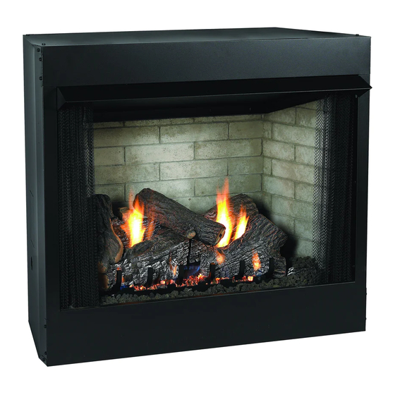
The Keystone "B" Vent Zero Clearance Gas
Fireplace
Installer: Leave these instructions with the consumer.
Consumer: Retain these instructions for future use.
WARNING: If the information in this manual is not
followed exactly, a fire or explosion may result causing
property damage, personal injury or loss of life.
- Do not store or use gasoline or other flammable
vapors and liquids in the vicinity of this or any
other appliance.
- WHAT TO DO IF YOU SMELL GAS
● Do not try to light any appliance.
● Do not touch any electrical switch; do not use any
phone in your building.
● Immediately call your gas supplier from a neighbors
phone. Follow the gas supplier's instructions.
● If you cannot reach your gas supplier, call the fire
department.
- Installation and service must be performed by
a qualified installer, service agency, or the gas
supplier.
INSTALLATION INSTRUCTIONS
OWNER'S MANUAL
GAS-FIRED
AND
B-VENT
GAS FIREPLACE
MODEL SERIES
millivolt
BVD34FP30(F,L)N-1
BVD36FP32(F,L)N-1
BVP42FP32(F,L)N-2
DiRECt iGNitioN
BVD34FP50(F,L)N-1
BVD36FP52(F,L)N-1
BVP42FP52(F,L)N-2
UL FILE NO. MH45034
NOT INTENDED FOR USE AS A PRIMARY HEAT
SOURCE. This appliance is tested and approved as
either supplemental room heat or as a decorative
appliance. It should not be factored as primary heat
in residential heating calculations.
This appliance is only for use with the type of gas
indicated on the rating plate. This appliance is not
convertible for use with other gases, unless a certified
kit is used.
WARNING: If not installed, operated and maintained
in accordance with the manufacturer's instructions,
this product could expose you to substances in fuel or
from fuel combustion which can cause death or seri-
ous illness.
Page 1
Advertisement
Table of Contents
Troubleshooting

Related Manuals for Empire Comfort Systems BVD34FP


Summary of Contents for Empire Comfort Systems BVD34FP
-
Page 1: Installation Instructions
INSTALLATION INSTRUCTIONS OWNER’S MANUAL The Keystone "B" Vent Zero Clearance Gas B-VENT Fireplace GAS FIREPLACE MODEL SERIES millivolt BVD34FP30(F,L)N-1 BVD36FP32(F,L)N-1 BVP42FP32(F,L)N-2 DiRECt iGNitioN BVD34FP50(F,L)N-1 BVD36FP52(F,L)N-1 GAS-FIRED BVP42FP52(F,L)N-2 UL FILE NO. MH45034 Installer: Leave these instructions with the consumer. Consumer: Retain these instructions for future use. WARNING: If the information in this manual is not followed exactly, a fire or explosion may result causing property damage, personal injury or loss of life. -
Page 2: Table Of Contents
TABLE OF CONTENTS Section Page Important Safety Information ....................3 Safety Information for Users of LP Gas ..................4 Introduction ..........................5 Specifications..........................6 Fireplace Dimensions ........................6 Clearances ..........................7 Locating Fireplace ........................7 Gas Supply ..........................8-9 Installation .........................10-11 Venting..........................12-13 Log Placement (BVD34 and BVD36) (5 Log Set) ..............14 Log Placement (BVP42) (4 Log Set) ..................15 Operating Instructions ......................16-17 Standing Pilot Wiring Diagram ....................18... -
Page 3: Important Safety Information
IMPORTANT SAFETY INFORMATION Before enclosing the vent pipe assembly, operate the appliance to ensure it is venting properly. • If this appliance is installed directly on carpeting, • Clothing or other flammable material should not be tile or other combustible material other than wood placed on or near the appliance. -
Page 4: Safety Information For Users Of Lp Gas
SAFETY INFORMATION FOR USERS OF LP GAS propane (lp-Gas) is a flammable gas which can cause fires by point with the members of your household. Someday when and explosions. In its natural state, propane is odorless and there may not be a minute to lose, everyone’s safety will depend colorless. -
Page 5: Introduction
INTRODUCTION Instructions to Installer shown in these instructions or use with a type of gas not shown on 1. Installer must leave instruction manual with owner after the rating plate is the responsibility of the person and company installation. making the change. 2. Installer must have owner fill out and mail warranty card supplied Important with the fireplace. -
Page 6: Specifications
18 3/8" (467mm) Gas Inlet Shutoff Valve (Pipe) 1/2 NPT 1/2 NPT 1/2NPT *NOTE: LP Conversion kits are included on the 120v. direct ignition model fireplaces. For millivolt models, use kit #19160 for BVD34FP Series, kit #19161 for BVD36FP Series, and kit #19162 for BVP42FP Series. Remote Control Options & Description Accessories FRBC MILLIVOLT BATTERY REMOTE ON/OFF... -
Page 7: Clearances
CLEARANCES Mantel Chart (Figure 3) Clearance to Combustibles 12” (305mm) Back 0" (0 mm) 10” (254mm) Side 0" (0 mm) Floor 0" (0 mm) MANTEL Top Stand-off 0" (0 mm) Top Framing Edge 1" (25mm) COMBUSTIBLE TRIM AND MANTELS 8” ALLOWED IN SHADED AREA 6”... -
Page 8: Gas Supply
GAS SUPPLY The gas pipeline can be brought in through the right or left side of Installing a New Main Gas Cock the appliance. Consult the current National Fuel Gas Code, ANSI Each appliance should have its own manual gas cock. Z223.1 CAN/CGA-B149 (.1 or .2) installation code. -
Page 9: Gas Supply
GAS SUPPLY (CONT) Checking Manifold Pressures Both Propane and Natural gas valves have a built-in pressure regulator in the gas valve. Natural gas models will have a manifold pressure of approximately 3.5" w.c. (.871kPa) at the valve outlet with the inlet pressure to the valve from a minimum of 4.5" w.c. (1.120kPa) for the purpose of input adjustment to a maximum of 14.0"... -
Page 10: Installation
INSTALLATION Install the fresh Air Kit - BVA1 Framing and Finishing A fresh air kit is available as an optional feature with this appliance. 1. Choose unit location. The fresh air kit helps to decrease the amount of room air taken by 2. Frame in fireplace with a header across the top. It is important utilizing outside air for combustion. -
Page 11: Installation
INSTALLATION (CONT) Combustible Surround Installation MANTELSHELF COMBUSTIBLE SURROUND FINISHED WALL 2 X 4 HEADER FRONT TRIM OR NON-COMBUSTIBLE MATERIAL MAY OVERLAP BLACK PAINTED STAND OFF FACE (INSTALLATION IS OPTIONAL) JOINT BETWEEN FINISHED WALL AND UNIT SEALED WITH 300° F 149 °... -
Page 12: Venting
VENTING Vent runs Note that for steep roof pitches, the vent height must be increased. In planning the installation for the fireplace, it is necessary to install In high wind conditions, nearby trees, adjoining roof lines, steep certain components before the appliance is completely positioned pitched roofs, and other similar factors can result in poor draft, and installed. -
Page 13: Venting
VENTING (CONT) Vent size offset Venting - with elbows Model BVD34FP series uses a 4" B-Vent for operation. Maximum horizontal Models BVD36FP and BVP42FP series use a 6" B-Vent for distance is 50% of vertical vent height operation. never downsize venting diameters. -
Page 14: Log Placement (Bvd34 And Bvd36) (5 Log Set)
LOG PLACEMENT (5 LOG SET) Before you begin: if you are installing logs into the BVD34 or BVD36 model, then this fireplace is supplied with a set of five ceramic fiber logs. Do not handle these logs with your bare hands! Always wear gloves to prevent skin irritation from ceramic fibers. After handling logs, wash your hands gently with soap and water to remove any traces of fibers. -
Page 15: Log Placement (Bvp42) (4 Log Set)
loG plACemenT (4 loG seT) Before you begin: This fireplace is supplied with a set of three ceramic fiber logs. Do not handle these logs with your bare hands. Always wear gloves to prevent skin irritation from ceramic fibers. After handling logs, wash your hands gently with soap and water to remove any traces of fiber. The positioning of logs is critical to safe and clean operation of this fireplace. Sooting and other problems may result if the logs are not properly and firmly positioned in the fireplace. Please refer to Figure 18, Figure 19, and Figure 20 and corresponding Figure 19 WARNING, when completing the following log placement WARNING: Failure to position the parts in accordance... -
Page 16: Operating Instructions
OPERATING INSTRUCTIONS 750 Millivolt System The OWNER should carefully read and follow these operating The standing pilot (750 millivolt system) is a continuous burning instructions at all times. Lower the door assembly to view the gas pilot. The pilot remains ON even when the main burner is OFF. controls for the fireplace. -
Page 17: Operating Instructions
OPERATING INSTRUCTIONS (CONT) Electric (120 volt) Operated Remote Control, FREC STANDING PILOT OPERATING INSTRUCTIONS The fireplace is equipped with a 15 foot length of wire that can be CAUTIon: Disconnect all electrical supply to the fireplace used to connect the valve to a wall switch (installer provided) or prior to installing the remote control optional equipment. -
Page 18: Standing Pilot Wiring Diagram
STANDING PILOT WIRING DIAGRAM (OPTIONAL) REMOTE CONTROL RECEIVER (FACULTATIVE) CONTROLE E DISTANCE DU RECEPTEUR WALL SWITCH INTERRUPTEUR MURAL LIMIT SWITCH THERMOPILE GAS VALVE (OPTIONAL) THERMOSTAT PILOT (FACULATIVE) THERMOSTAT VEILLEUSE WALL SWITCH/REMOTE CONTROL RECEIVER/ THERMOSTAT CONTROLE E DISTANCE DU RECEPTEUR GAS VALVE VALVE DE GAZ Figure 23 Page 18... -
Page 19: Standing Pilot Lighting Instructions
STANDING PILOT LIGHTING INSTRUCTIONS FOR YOUR SAFETY, READ BEFORE LIGHTING WARNING: IF YOU DO NOT FOLLOW THESE INSTRUCTIONS EXACTLY, A FIRE OR EXPLOSION MAY RESULT CAUSING PROPERTY DAMAGE, PERSONAL INJURY, OR LOSS OF LIFE A. This appliance has a pilot which must be lighted by hand. •... -
Page 20: Standing Pilot Troubleshooting
STANDING PILOT TROUBLESHOOTING With proper installation and maintenance, your new Gas Fireplace will provide years of trouble-free service. If you do experi- ence a problem, refer to the Trouble shooting Guide below. This guide will assist a qualified service person in the diagnosis of problems and the corrective action to be taken. -
Page 21: Standing Pilot Propane/Lp Gas Conversion
1.45mm 1.65mm WARNING Dexen 10" w.c. R-7548 R-7548 R-7548 Regulator This conversion kit is to be installed by an Empire Comfort Systems, Gas Conversion 2139 2139 2139 Inc. dealer (or other qualified agency )* in accordance with the Label manufacturer's instructions and all codes and requirements of the authority having jurisdiction. - Page 22 IMPORTANT: Failure to install the correct orifice will result If the appliance has not been installed, or a warranty card has not in unit over-firing that could overheat the appliance and result been returned to Empire Comfort Systems, Inc., check off type of in a fire. gas converted to on card (for reference once the unit is installed). Also, indicate conversion by adding "Conv." behind gas.
-
Page 23: Direct Ignition Wiring Diagram
DIRECT IGNITION WIRING DIAGRAM GAS VALVE SPARK IGNITOR VALVE DE GAZ (OPTIONAL) WALL SWITCH ÉTINCELLE ALLUMER INTERRUPTEUR MURAL (FACULTATIVE) CONTROL MODULE (OPTIONAL) REMOTE CONTROL AUTORITÉ MODULE RECEIVER 120V (FACULATIVE) CONTROLE E DISTANCE DU RECEPTEUR 120 VAC LINE BLACK NOIR 120 VAC RTN BLACK NOIR WHITE BLANC LIMIT SWITCH... -
Page 24: Direct Ignition Lighting Instructions
DIRECT IGNITION LIGHTING INSTRUCTIONS FOR YOUR SAFETY READ BEFORE LIGHTING WARNING: IF YOU DO NOT FOLLOW THESE INSTRUCTIONS EXACTLY, A FIRE OR EXPLOSION MAY RESULT CAUSING PROPERTY DAMAGE, PERSONAL INJURY, OR LOSS OF LIFE. A. BEFORE LIGHTING smell all around the appliance area • If you can not reach your gas supplier, call the fire for gas. Be sure to smell next to the floor because some gas department. -
Page 25: Direct Ignition Troubleshooting
DIRECT IGNITION TROUBLESHOOTING With proper installation and maintenance, your new Gas Fireplace will provide years of trouble-free service. If you do experience a problem, refer to the troubleshooting guide below. This guide will assist a qualified service person in the diagnosis of problems and the corrective action to be taken. Refer to page 24 for initial startup and GAS Line purge instructions. SYMPTOM CHECK ACTION... -
Page 26: Direct Ignition Propane/Lp Gas Conversion
DIRECT IGNITION PROPANE/LP GAS CONVERSION 1. Turn off the gas supply. 18. Loosen screw and attach a manometer or pressure gauge to 2. Turn off the electrical supply to the appliance if so the outlet pressure tap of the control valve. equipped. -
Page 27: Maintenance And Service
MAINTENANCE AND SERVICE Glass Cleaning (optional Kits) PLEASE NOTE It will be necessary to clean the glass periodically. During start-up It is normal for appliances fabricated of steel to give off condensation, which is normal, forms on the inside of the glass and some expansion and/or contraction noise during the start causes lint, dust and other airborne particles to cling to the glass up or cool down cycle. -
Page 28: Bvd34 And Bvd36 Parts List
BVD34 & BVD36 PARTS LIST INDEX PART NUMBER DESCRIPTION BVD34L BVD34F BVD36L BVD36F 19506 19506 19507 19507 TOP SHIELD 17301 17301 17301 17301 TOP STANDOFF (2 REQUIRED) 10554 10554 10554 10554 NAILING FLANGE (4 REQUIRED) M163 M163 M178 M178 FLUE OUTLET GASKET 19387 19387 19422... -
Page 29: Bvd34 And Bvd36 Parts View
BVD34 & BVD36 PARTS VIEW MILLIVOLT BURNER ASSEMBLY DIRECT IGNITION BURNER ASSEMBLY 5 PIECE LOG ASSEMBLY 22679-1-0408 Page 29... -
Page 30: Bvp42 Parts List
BVP42 PARTS LIST INDEX NO. PART NUMBER PART NUMBER DESCRIPTION BVP42L BVP42F 19508 19508 TOP SHIELD 17247 17247 TOP STANDOFF (2 REQUIRED) 10554 10554 NAILING FLANGE (4 REQUIRED) M178 M178 FLUE OUTLET GASKET 19422 19422 FLUE OUTLET ASSEMBLY 19398 19398 DOWNDRAFT BAFFLE 19467 19467... -
Page 31: Bvp42 Parts View
BVP42 PARTS VIEW MILLIVOLT BURNER ASSEMBLY DIRECT IGNITION BURNER ASSEMBLY 4 PIECE LOG ASSEMBLY 22679-1-0408 Page 31... -
Page 32: Fbb4 Optional Variable Speed Blower Installation Instructions
FBB4 OPTIONAL VARIABLE SPEED BLOWER INSTALLATION Attention: Install blower assembly before connecting gas inlet 5. Insert blower assembly into interior, bottom of fireplace. supply line Position blower assembly behind gas valve, align notch on back of blower assembly with center screw on fireplace back Note: Junction box on right side of fireplace must be pre-wired at and push blower assembly against fireplace back. The magnets time of fireplace installation for use with blower assembly. on the back and bottom of blower assembly will sufficiently It is recommended that an ON/OFF wall switch be hold blower assembly in place. - Page 33 FBB4 OPTIONAL VARIABLE SPEED BLOWER INSTALLATION fBB4 BLOWER ASSEMBLY COMPLETE r7649 FAN CONTROL r4192 SPEED CONTROL KnoB r4186 SPEED CONTROL Figure 26 110 VOLT AC JUNCTION BOX BLACK SWITCH WHITE GROUND SPEED CONTROL Figure 27 22679-1-0408 Page 33...
-
Page 34: Junction Box Wiring Installation Instructions
JUNCTION BOX WIRING INSTALLATION INSTRUCTIONS sTAnDArD mIllIVolT VAlVe moDels CAUTION: ALL WIRING SHOULD BE DONE BY A QUALIFIED ELECTRICIAN AND SHALL BE IN COMPLIANCE WITH ALL loCAl, CITY AnD sTATe BUIlDInG CoDes. Before mAKInG The eleCTrICAl ConneCTIon, mAKe sUre ThAT MAIN POWER SUPPLY IS DISCONNECTED. -
Page 35: Optional Accessories
OPTIONAL ACCESSORIES The following accessory parts can be obtained from your Empire Comfort Systems dealer. If you need additional information beyond what your dealer can furnish, contact Empire Comfort Systems Inc., Nine Eighteen Freeburg Ave., Belleville, Illinois 62220-2623. Accessory Description... -
Page 36: Decorative Accessories
DECORATIVE ACCESSORIES Decorative Louver Mission Decorative Louver Arch Decorative Louver Leaf Decorative Frame Rectangle Decorative Door Mission Decorative Door Leaf Decorative Door Plain with hinges Rectangle Rectangle Rectangle Decorative Frame Arch with Decorative Door Leaf Arch Decorative Door Mission Arch Decorative Door Plain Arch hinges Bottom Trim Frame... -
Page 37: How To Order Repair Parts
Type of Gas (Propane or Natural) Do not order bolts, screws, washers or nuts. They are standard hardware items and can be purchased at any local hardware store. Shipments contingent upon strikes, fires and all causes beyond our control. Empire Comfort Systems, Inc. Nine Eighteen Freeburg Ave. Belleville, Illinois 62222-2623 22679-1-0408 Page 37... -
Page 38: Service Notes
SERVICE NOTES Page 38 22679-1-0408... - Page 39 SERVICE NOTES 22679-1-0408 Page 39...
- Page 40 Empire Comfort Systems Inc. EMPIRE EMPIRE 918 Freeburg Ave. Belleville, IL 62220 If you have a general question about our products, please e-mail us at info@empirecomfort.com. If you have a service or repair question, please contact your dealer. Comfort Systems www.empirecomfort.com Page 40 22679-1-0408...