Table of Contents
Advertisement
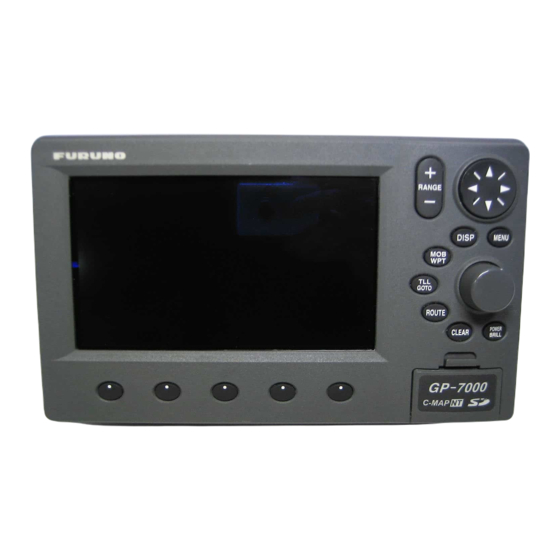
COLOR GPS PLOTTER GP-7000
SAFETY INSTRUCTIONS ............................................................................ i
SYSTEM CONFIGURATION ....................................................................... ii
EQUIPMENT LISTS.................................................................................... iii
1. INSTALLATION ..................................................................................... 1
1.1
Display Unit .................................................................................................................. 1
1.2
Antenna Unit................................................................................................................. 4
2. WIRING .................................................................................................. 5
3. ADJUSTMENTS .................................................................................... 9
3.1
Choosing Position Data Source.................................................................................... 9
3.2
Choosing Port I/O Format........................................................................................... 11
3.3
Calibrating NMEA Depth, Speed and Water Temperature Data ................................ 13
3.4
Waypoint, Route Format............................................................................................. 14
3.5
External Event Format ................................................................................................ 14
3.6
C-link (primary and secondary stations) ..................................................................... 15
PACKING LIST ........................................................................................ A-1
OUTLINE DRAWINGS............................................................................. D-1
INTERCONNECTION DIAGRAM ............................................................ S-1
Installation Manual
www.furuno.co.jp
Back
Advertisement
Table of Contents

Related Manuals for Furuno GP-7000


Summary of Contents for Furuno GP-7000
-
Page 1: Table Of Contents
Back Installation Manual COLOR GPS PLOTTER GP-7000 SAFETY INSTRUCTIONS ................i SYSTEM CONFIGURATION ............... ii EQUIPMENT LISTS..................iii 1. INSTALLATION ..................1 Display Unit ........................1 Antenna Unit......................... 4 2. WIRING ....................5 3. ADJUSTMENTS ..................9 Choosing Position Data Source..................9 Choosing Port I/O Format................... -
Page 2: Safety Instructions
SAFETY INSTRUCTIONS WARNING CAUTION ELECTRICAL SHOCK HAZARD Observe the following compass safe Do not open the equipment distances to prevent interference to a unless totally familiar with magnetic compass: electrical circuits and Standard Steering service manual. compass compass Only qualified personnel Display 0.70 m 0.45 m... -
Page 3: System Configuration
SYSTEM CONFIGURATION ANTENNA UNIT GPA-017 DISPLAY UNIT GP-7000 NMEA1 and NMEA2 ports: Radar, autopilot, video sounder, temperature indicator, etc. PC/NMEA IN port: PC, NMEA device, buzzer : Standard : Option : User Supply Power Source 12-24 VDC How to remove the hard cover... -
Page 4: Equipment Lists
EQUIPMENT LISTS Standard supply Name Type Code No. Remarks Display Unit GP-7000 — GPA-017 System also available without antenna (for boats Antenna Unit — which already have an appropriate antenna) Installation CP14-06400 000-041-183 Materials* Accessories* FP20-01100 000-042-239 Spare Parts* SP14-03201 004-371-980 * See packing list at back of this manual. -
Page 5: Installation
1. INSTALLATION 1.1 Display Unit The display unit may be mounted on a desktop, overhead or flush mounted in a console. Mounting considerations Choose a mounting location for the display unit considering the following points: • Choose a location where the controls can be easily operated. •... - Page 6 Mounting Desktop, overhead mounting 1. Fix the hanger to the mounting location with four self-tapping screws (5X20). See the outline drawing on page D-1 for complete mounting dimensions. 2. Loosely screw the knob bolts into the display unit. 3. Set the display unit to the hanger and tighten the knob bolts. 4.
- Page 7 Flush mounting If the thickness of the console is 11-14 mm, use the washer head screws (M4X20) supplied with the installation materials. If it is thicker than those dimensions, the length of the screws should be the thickness of the console plus 7.3 mm ±1.5 mm. The length of the threaded portion to be inserted to the display unit should not exceed 7 mm (B≤7).
-
Page 8: Antenna Unit
1.2 Antenna Unit Refer to the antenna unit outline drawing at the back of this manual for mounting instructions. When selecting a mounting location consider the following points: • Select a location out of the radar and Inmarsat beams. Those beams will obstruct or prevent reception of the GPS satellite signal. -
Page 9: Wiring
2. WIRING The figure below shows the basic wiring scheme. ANTENNA UNIT GPA-017 FROM LEFT PC/NMEA IN: PC, NMEA device, buzzer, AIS NMEA 2: Radar, autopilot, video sounder, temperature indicator, etc. NMEA 1: Same as NMEA 2 Ground Antenna Cable, 10 m MJ-A15A3F0013-035-3A, 3.5 m White... -
Page 10: Antenna Cable
Ground Connect the ground wire to the boat's grounding bus. If the unit is not grounded, noise may result. If noise is a problem on an FRP vessel, fasten a ground plate of 20 cm x 30 cm to the outside of the ship's hull and connect the ground wire there. - Page 11 Waterproofing the connector If you are using the extension cable, connect the cable and then wrap the connector with self-vulcanizing tape and then vinyl tape to waterproof it. Bind ends of vinyl tape with cable ties (local supply) to prevent unraveling. How to waterproof the connector...
- Page 12 How to attach N-P-8DFB connector (for extension cable kit) Dimensions in millimeters. Outer Sheath Armor Inner Sheath Shield Remove outer sheath and armor by the dimensions shown left. Expose inner sheath and shield by the dimensions shown left. Cover with heat-shrink tubing and heat. Cut off insulator and core by 10 mm.
-
Page 13: Adjustments
3. ADJUSTMENTS This chapter shows you how to adjust your unit, from the menu. When choosing item or option from the menu, you may use the [ENTER] knob or the CursorPad ( ). For sake of brevity the descriptions contained herein use the [ENTER] knob. Choosing Position Data Source If you intend to use a position data from a source other than the internal GPS receiver follow the procedure below. - Page 14 3. Rotate the [ENTER] knob to choose INPUT/OUTPUT and then push the [ENTER] knob. INTERNAL GPS SETUP NMEA 1 INPUT NMEA-0183 4800-N81-N NMEA 1 OUTPUT NMEA 2 INPUT NMEA-0183 4800-N81-N NMEA 2 OUTPUT RS232/NMEA 3 INPUT NMEA-0183 4800-N81-N RS232C 3 OUTPUT INPUT 3 MODE RS232C WPL/RTE FORMAT...
-
Page 15: Choosing Port I/O Format
Choosing Port I/O Format 1. Press the [MENU] key to show the menu bar. 2. Rotate the [ENTER] knob to choose ADVANCED from the menu bar and then push the [ENTER] knob. 3. Rotate the [ENTER] knob to choose INPUT/OUTPUT and then push the [ENTER] knob. 4. - Page 16 Output 1) Rotate the [ENTER] knob to choose appropriate option and then push the [ENTER] knob. 2) Rotate the [ENTER] knob to choose Off or On as appropriate and then push the [ENTER] knob followed by 6. Repeat step 5 to set up other ports. 7.
-
Page 17: Calibrating Nmea Depth, Speed And Water Temperature Data
3.3 Calibrating NMEA Depth, Speed and Water Temperature Data NMEA speed, depth and water temperature data may be corrected from the GP-7000 if they cannot be done from the equipment that outputs the data. Enter a minus value if the actual value is lower than the NMEA data, or a plus value if the actual value is higher than the NMEA data. -
Page 18: Waypoint, Route Format
Waypoint, Route Format You may transfer waypoint and route data to another GP-7000 series unit or a PC in Standard or Furuno format, via the NMEA1 port, NMEA2 port or PC NMEA IN port. 1. Press the [MENU] key to show the menu bar. -
Page 19: C-Link (Primary And Secondary Stations)
3.6 C-link (primary and secondary stations) The C-link feature, available when several GP-7000 series units are interconnected via NMEA ports or PC/NMEA IN ports (see the illustration below), lets you duplicate on secondary stations the destination set at the primary station. With this feature active destination may only be set from the primary station. - Page 28 : +81-(0)798-65-4200 A : AUG 2004 Printed in Japan All rights reserved. C1 : JUN . 21, 2007 Pub. No. IME-44290-C1 *00014913612* *00014913612* (HIMA ) GP-7000 *00014913612* *00014913612* * 0 0 0 1 4 9 1 3 6 1 2 *...