Table of Contents
Advertisement
Advertisement
Table of Contents
Troubleshooting

Related Manuals for Husqvarna Robotic Lawn Mowe


Summary of Contents for Husqvarna Robotic Lawn Mowe
- Page 1 operator’s manual...
- Page 2 The concept behind the Automower comes straight out of nature - the principle of the grazing animal. Which means basically that the grass is cut a little and often. This is not only more efficient, it’s better for the grass too. Please read this Operator’s Manual carefully before using the machine.
-
Page 3: Table Of Contents
Table of contents 1. Introduction and safety 1.1 Introduction 1.2 Symbols on Automower 1.3 Symbols in the Operator’s Manual 1.4 Safety instructions 2. Presentation 2.1 Automower, what’s what? 2.2 Function of Automower 2.3 Search method 2.4 More than one Automower in a garden 2.5 One Automower in several gardens 3. - Page 4 Table of contents Husqvarna AB has a policy of continuous product development and therefore reserves the right to modify the design and appearance and function of products without prior notice. This Operator's Manual deals with version 2.3x of the mower’s control program.
-
Page 5: Introduction And Safety
1.1 Introduction Congratulations on your choice of an exceptionally high quality product. To get the best results from your Automower from Husqvarna™ requires knowledge of its function. This Operator's manual contains important information about the mower, how you install it and how you use it. -
Page 6: Symbols On Automower
1. Introduction and safety 1.2 Symbols on Automower These symbols can be found on the lawn mover. Study them carefully so you understand their significance. • Read through the Operator’s Manual carefully and understand the content before using your Automower. •... -
Page 7: Symbols In The Operator's Manual
1.3 Symbols in the Operator’s Manual These symbols can be found in the Operator’s Manual. Study them carefully so you understand their significance. • Inspection and/or maintenance must be carried out with the main switch set to OFF. • Always wear protective gloves when working with the mower’s underframe. -
Page 8: Safety Instructions
1. Introduction and safety 1.4 Safety instructions • Please read the Operator's Manual carefully and make sure you understand the instructions before using Automower. • It is not permitted to modify the original design of the Automower. All modifications are made at your own risk. - Page 9 Transport The original packaging should be used when transporting the Automower over long distances. To safely move from or within the working area: Press the STOP button to stop the mower. If the stop protection, (see page 61) used to prevent theft, has been activated enter the first number of the PIN code.
-
Page 10: Presentation
2. Presentation This chapter contains information you should be aware of when planning the installation. An installation of Automower from Husqvarna™ includes four main components: Automower, an automatic lawn mower that mows the lawn by moving in essentially an irregular pattern. -
Page 11: Automower, What's What
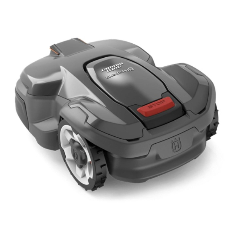
2.1 Automower, what’s what? The numbers in the picture correspond to: Charging strip Cutting height adjustment cover Catch button to open the cutting height adjustment cover Front wheel Drive wheel Body Stop button Keypad Display 10. Main switch 11. Handle 12. -
Page 12: Function Of Automower
2. Presentation 2.2 Function of Automower Capacity The Automower is recommended for lawns up to 1,800 m Automower mows about 75 m per hour. How large an area is mown depends primarily on the condition of the blades and the type of grass, growth rate and humidity. The shape of the garden is also significant. - Page 13 2. Presentation Working method The Automower automatically mows the lawn. It continuously combines mowing and charging. The charging station sends out a signal that the Automower can sense at a distance of 6 - 7 metres. The mower starts to search for the charging station when the battery charge becomes too low.
- Page 14 2. Presentation The STOP button on the top of Automower is mainly used to stop the mower when it’s running. When the STOP button is pressed a cover opens, behind which there is a control panel. The STOP button remains depressed until the cover is closed again.
-
Page 15: Search Method
Movement pattern The mower’s movement pattern is irregular and is determined by the Automower itself. A movement pattern is never repeated. This mowing system means the lawn is mown equally without any mowing lines. If the Automower enters an area where it senses the grass is longer than earlier, it can change the movement pattern. - Page 16 2. Presentation Search method 2: Follow loop in Automower runs irregularly until it reaches the boundary wire. The mower then follows the boundary wire in to the charging station. This search method is best for an installation that has an open lawn with wide passages (wider than about 3 metres) and no, or only a small, island.
-
Page 17: More Than One Automower In A Garden
2. Presentation 2.4 More than one Automower in a garden If you install more than one Automower in the same area of lawn, each mower must have its own PIN code. However, if the boundary wires are laid at least 40 cm from each other the mowers can have the same PIN code. -
Page 18: Installation
3. Installation 3. Installation This chapter describes how you install Automower from Husqvarna™. Before starting the installation read the previous chapter 2. Presentation. Read the whole of this chapter too before starting the installation. How the installation is made also affects how well Automower will work. -
Page 19: Preparations
3.1 Preparations If the lawn in the proposed working area is taller than 10 cm, mow it using a normal lawn mower. Then collect the clippings. Read carefully through all the steps before the installation. Check that all parts for the installation are... - Page 20 3. Installation The charging station must be positioned with a great deal of free area in front of it (at least 3 metres). It should also be positioned centrally in the working area so that Automower can easily find the charging station and quickly reach all parts of the working area.
- Page 21 Do not put the charging station in a corner or pocket in the working area. Avoid placing the charging station in a narrow passage (narrower than about 3 metres). Installation and connecting the charging station Position the charging station in a suitable spot. Secure the charging station to the ground using the supplied nails.
- Page 22 3. Installation Connect the low voltage cable to the charging station. Only use original cable and transformer. Connect the low voltage cable to the transformer. The connectors may be slightly difficult to connect, as they are moisture-proof. Connect the transformer’s power cord to a 230V wall socket.
-
Page 23: Charging The Battery
3.3 Charging the battery The Automower is supplied with an uncharged battery. As soon as the charging station is connected, it is possible to charge the mower. Set the main switch to the OFF position. Place the Automower in the charging station to charge the battery while you are laying the boundary wire. - Page 24 3. Installation • The boundary wire is laid at different distances from obstacles depending on what the working area borders. The picture below shows how the boundary wire should be routed around the working area and around obstacles. Boundaries for the working area If a high obstacle, for example a wall or fence, borders the working area, the boundary wire should be laid 35 cm from the obstacle.
- Page 25 3. Installation If the working area borders against a flat path or the like that lies level with the lawn, it is possible to allow the Automower to run a little over the path. The boundary wire should then be laid 10 cm from the edge of the path.
- Page 26 3. Installation Boundaries within the working area Use the boundary wire to demarcate areas inside the working area by creating islands around obstacles that can not withstand a collision, for example, flower beds and fountains. Run the cable out to the area, route it around the area to be demarcated and then back along the same route.
- Page 27 Passages when mowing Long narrow passages and areas, narrower than 1.5 - 2 metres, should be avoided. When Automower mows there is a risk that it runs around in the passage or area for a too long a period. The lawn will then look flattened.
- Page 28 3. Installation Slopes The boundary wire can be laid across a slope that slants less than 10 %. The boundary wire should not be laid across a slope that is steeper than 10 %. There is a risk of Automower finding it difficult to turn there. The mower will then stop and show the fault message Outside working area.
- Page 29 • Mow the lawn where the wire is to be laid using a normal lawn mower or a trimmer. It will then be easier to lay the wire close to the ground and the risk of the mower cutting the wire off is reduced.
- Page 30 3. Installation If you intend to bury the boundary wire: • Make sure to place the boundary wire at least 1 cm and a maximum of 20 cm into the ground. The boundary wire must not cross the path to and from an island.
-
Page 31: Connecting The Boundary Wire
Joining the boundary wire If the boundary wire is not long enough and needs to be spliced: Use original solderless coupler, part number 535 13 37-01. It is waterproof and gives a reliable electrical connection. To splice: Insert both cable ends in the coupler. Now press down the button on top of the connector fully. - Page 32 3. Installation Slide in the ends of the boundary wire in the lowermost holes on the charging station and catch them in the uppermost holes. The right hand wire end should be inserted in the right hand hole, and the left hand wire end in the left hand hole.
-
Page 33: Checking The Installation
Cut off any surplus boundary wire. Cut 1 - 2 cm above respective connectors. Press the connector onto the contact pin, marked A, on the charging station. IMPORTANT INFORMATION The right hand connector should be connected on the right hand contact pin on the charging station and vice versa. -
Page 34: Linking The Automower To The Charging Station
3. Installation 3.7 Linking the Automower to the charging station Open the control panel cover by pressing the STOP button. Place the Automower in the charging station. Set the main switch to the ON position. A start-up sequence begins when the Automower is started for the first time. - Page 35 • The boundary wire runs along a steep slope (steeper than 35 %). When Automower follows the boundary wire that runs along a steep slope, the mower will change direction and run away from the boundary wire. • Numerous or large islands. If Automower is permitted to follow the boundary wire it may circle an island roughly twice before it leaves the island and once again searches for...
- Page 36 3. Installation Placement and connection of the guide wire Check that the charging station has the best placement. The guide wire together with the part of the boundary wire that makes up the return to the charging station is known as the guide loop. The current in the guide loop always goes to the left in the connection between the guide wire and the boundary wire.
- Page 37 Route the guide wire at least 2 metres straight out from the front edge of the charging plate. If you shall install the guide wire through a passage: • Automower follows the guide wire on the same side of the wire both to and from the charging station.
- Page 38 3. Installation 11. Connect the guide wire to the boundary wire with the help of a solderless coupler: • Insert the ends of the boundary wire in the right respective left-hand holes on the connector. • Insert the end of the guide wire in the centre hole.
-
Page 39: Use
4. Use 4.1 Charging a discharged battery When Automower from Husqvarna™ is new or has been stored for a long period the battery will not be charged and needs to be charged before starting. Charging takes between 1 1/2 and 2 1/2 hours. -
Page 40: Using The Timer
4. Use 4.2 Using the timer The lawn should not be cut too often to obtain the best mowing result. Use the timer function (see 6.4 Timer (2) on page 49) to avoid a downtrodden lawn and to get the maximum life from your Automower. For example, the quality of your lawn will improve if it is mown every other day instead of 12 hours each day. -
Page 41: Restart
4.5 Restart Restart within 20 seconds Close the control panel cover. The Automower starts automatically. Restart after more than 20 seconds If more than 20 seconds has elapsed since the last time the STOP button or the keypad was pressed it is not possible to start the Automower by just closing the cover. -
Page 42: Adjusting The Cutting Height
4. Use 4.7 Adjusting the cutting height The cutting height can be varied from MIN (2 cm) to MAX (6 cm). If the grass is long it is appropriate to let Automower start mowing at the MAX cutting height. Once the grass is shorter, you can gradually lower the cutting height. -
Page 43: Control Panel
5. Control panel All forms of commands and settings for Automower from Husqvarna™ are made via the control panel. All functions are accessed via a number of menus. The control panel consists of a display and a keypad. All information is shown on the display and all input is done using the buttons. -
Page 44: Shortcuts
5. Control panel The keypad consists of five groups of buttons: Shortcuts, program, selection, numbers and the main switch. 5.1 Shortcuts Home: • Sends the mower to the charging station. Where it stays until the button is pressed again. The house icon is lit on the right-hand side of the display when the button is pressed. -
Page 45: Programs
5.2 Programs Under the program buttons you can save sets of different settings, to reuse or to simplify the use of an Automower in several gardens. Under respective buttons there are some preset settings. You can choose to use these or change them. •... -
Page 46: Numbers
5. Control panel 5.4 Numbers Used in the menu structure to enter settings, for example, PIN code, time or exit direction. Also used to specify a number series as a shortcut to the different menus. See more about number series in Number series on page 47. 5.5 Main switch 10. -
Page 47: Menu Functions
6.5 Garden (3) 6.6 Settings (4) The numbers in brackets refer to the menu rows on the display of the Automower from Husqvarna™. There are a number of submenus under each option. You can access all the functions to set the Automower settings via these. -
Page 48: Automower Main Menu, Menu Overview
6. Menu functions 6.2 Automower main menu, menu overview Automower from ™... -
Page 49: Commands (1)
6.3 Commands (1) This option in the main menu allows you to access the following functions on the Automower. • Charge then AUTO (1-1) in order for the Automower to drive immediately to the charging station, charge the battery and then return to the automatic operating mode. - Page 50 6. Menu functions Timer override (2-1) If you set the timer on your Automower you can use this function to temporarily get maximal operation from the mower. • YES (2-1-1) Move the cursor to YES and press YES to turn off the timer function.
-
Page 51: Garden (3)
Week timer (2-4) Use the YES button to select the days you would like the Automower to mow. • Mon (2-4-1) • Tue (2-4-2) • Wed (2-4-3) • Thu (2-4-4) • Fri (2-4-5) • Sat (2-4-6) • Sun (2-4-7) • Run all (2-4-8) Move the cursor to Run all and press YES. - Page 52 6. Menu functions Exit angles (3-1) Normally the Automower leaves the charging station in a direction within the exit sector 90°-270°, where 90° is called the Start angle and 270° is called the End angle. By setting the start and end angles, you can set the direction in which Automower is to leave the charging station.
- Page 53 • Proportion first (3-1-6) When you use two exit sectors: Specify a percentage to define on how many occasions the Automower should leave the charging station in sector 1. To test the settings in Exit angles: State the value 100 % for Proportion first when sector 1 is to be tested.
- Page 54 6. Menu functions Up to three remote areas can be activated: Area 1, Area 2 and Area 3. Three values need to be stated to activate an area: • Direction Specify to the right or left, depending on which direction the area lies from the charging station.
- Page 55 • Follow loop in (3-2-2) This function is used to control how Automower searches for the charging station. Automower always starts the search for the charging station in an irregular search method. In some gardens this is not sufficient for the mower to quickly find the charging station.
- Page 56 6. Menu functions • Corridor width (3-2-3) The Corridor width setting defines the distances from the mower's path to the boundary wire or the guide wire when following these to/from the charging station. The area beside the wires used by the mower is called the Corridor. A low corridor width value represents a narrow corridor while a high value represents a wide corridor.
- Page 57 • Test IN (3-2-4) The Test IN (3-2-4) function is used to test how Automower finds its way into the charging station. When the function is selected, the mower will directly follow the boundary wire or guide wire, depending on which one is found first, in to the charging station.
- Page 58 6. Menu functions To find out the distance from the charging station to a remote area: • State a distance that easily exceeds the true distance. The maximum distance that can be stated is 500 metres. State the value 100 % for Proportion for the area to which the distance is to be measured.
- Page 59 Advanced (3-4) • Check loop (3-4-1) This function allows you to check the mower’s signal reception from the boundary wire, and to determine exactly where in the lawn the boundary wire is routed. The sensor used for this function sits concealed directly under the catch button for the cutting height adjustment cover.
-
Page 60: Settings (4)
6. Menu functions 6.6 Settings (4) From this option in the main menu you access the settings. • Security (4-1) to make settings concerning the PIN code, stop protection, settings lock and alarms. The PIN code must be specified for the Security menu to be shown. - Page 61 • Activate: Move the cursor to Time lock and press YES. Now move the cursor to Number of days and press YES. Specify how many days you would like the Automower to mow before it requests the PIN code. Finish by pressing YES. When the selected number of days has elapsed, the Automower completes mowing and charges the battery.
- Page 62 6. Menu functions • Settings lock (4-1-4) This function prevents any one who does not know the PIN-code from changing any of the settings. It also prevents the A, B or C programs from being selected or saved. • Activate: Move the cursor to Settings lock and press YES.
- Page 63 Sound 2 beeps/10 seconds 5 beeps over 2 seconds 3 beeps/second One long beep Short click sound Muffled long beep Short double beep Language (4-3) Using this function you can change the language selection you made when the Automower was first started.
- Page 64 6. Menu functions Time and date (4-4) Using this function you can change the time and date on the Automower. You can also change the format selections you made when the Automower was first started via this function. • Set time (4-4-1) Move the cursor to Set time and press YES.
-
Page 65: Garden Example - Proposed Installation And Settings
Adapting the mower's garden settings according to the shape of the garden makes it easier for the Automower from Husqvarna™ to frequently reach all parts of the garden and in doing so achieve a perfect mowing result. - Page 66 7. Garden example - proposed installation and settings Proposals for installation and settings Area: 1,800 m . No guide wire is necessary. Timer: Operating time of 24 hours per day. Garden shape: Open. Exit angles: One sector 90°-270°. Search method: Irregular and Follow boundary wire in.
- Page 67 Proposals for installation and settings Area: 600 m . L-shaped garden with the charging station placed in the narrow area. There are two islands. No guide wire is necessary. Timer: Operating time of 8 hours per day. Garden shape: Open. Exit angles: Sector 1 70°...
- Page 68 7. Garden example - proposed installation and settings Proposals for installation and settings Area: 500 m . There are several islands. No guide wire is necessary. The mower’s default settings do not need to be changed. Timer: Operating time of 7 hours per day. Garden shape: Open.
- Page 69 7. Garden example - proposed installation and settings Proposals for installation and settings Area: 1,200 m . Guide wire recommended. Timer: Operating time of 19 hours per day. Garden shape: Complex. Exit angles: One sector 90°- 270°. Follow loop out: Direction Guide, Distance 40 m and Proportion 15 %.
-
Page 70: Maintenance
8. Maintenance 8. Maintenance Check and clean the Automower from Husqvarna™ regularly and replace worn parts if necessary to improve operating reliability and to ensure a longer service life. For further information on cleaning, see 8.5 Cleaning on page 72. -
Page 71: Battery
8.1 Battery The battery is maintenance-free, but has a limited life span of 1 - 3 years. Battery life is dependent on the length of the season and how many hours per day the Automower is used. A long season or many hours of use per day, means that the battery must be replaced more regularly. -
Page 72: After Winter Storage
8. Maintenance 8.4 After winter storage Check whether the Automower, contact strips or charging strips need to be cleaned before using. If the charging or contact strips appear to be burnt, clean them using fine grade emery cloth. Check that the mower’s time and date are correct. -
Page 73: Replacing The Blades
Chassis Clean both the top and underside of the chassis. Remove grass that has collected between the chassis and body. Brush or wipe with a damp cloth. IMPORTANT INFORMATION Do not use running water when cleaning. Wheels Clean around the front and rear wheels and around the front wheel suspension. - Page 74 8. Maintenance To replace the blades: Set the main switch to the OFF position. Wear protective gloves. Turn the Automower upside down. Rotate the skid plate so that its hole aligns with the screw for the blade. Unscrew the blade. Use a straight slot or cross-tip screwdriver.
-
Page 75: Trouble Shooting
9. Trouble shooting 9.1 Fault messages A number of fault messages are listed below that can be shown on the Automower from Husqvarna™. If another message than those listed is shown, contact your dealer. Fault message Cause Left wheel motor... - Page 76 9. Trouble shooting Fault message Cause Outside working area If this occurs in isolated areas it may be due to interference from metallic objects (perimeter fence, reinforcement bar) or buried cables in the vicinity. The working area slopes too much. The boundary wire has been routed the wrong way around an “island”.
-
Page 77: Trouble Shooting Guide
9.2 Trouble shooting guide If your Automower does not work correctly, follow the trouble shooting guide below. If the fault persists; contact your dealer. Symptom Cause Uneven mowing Automower works too few hours per results day. Working area too large. Dull blades. -
Page 78: Technical Data
Cutting width Working capacity 11. Environmental information The symbol on the Automower from Husqvarna™ or its packaging indicates that this product may not be treated as household waste. Instead it shall be handed over to the applicable collection point for the recycling of electrical and electronic equipment. -
Page 79: Eu Declaration Of Conformity
Husqvarna AB, SE-561 82 Huskvarna, Sweden, tel: +46-36-146500, declares under sole responsibility that the automatic lawn mower Automower from Husqvarna™ from year 2005 serial numbers and onward (the year is clearly stated in plain text on the rating plate with subsequent serial number), conforms with the requirements of the COUNCIL’S DIRECTIVE:... - Page 80 12. EU declaration of conformity Automower from ™...
-
Page 81: Index
13. Index Advanced ...59 Alarm ...61 Arrow down ...45 Arrow up ...45 AUTO ...44 Automower More than one in a garden ...17 One in several gardens ...17 Technical data ...78 What’s what ...11 Automower runs at the wrong time ...77 Automower runs, but the blade disc does not rotate .77 Battery Battery status ...43... - Page 82 13. Index Earth fault-breaker ...20 End angle ...52 Exit angles ...52 Exit sector ...52 Factory settings Automower ...49 Fault messages ...49 Fault symptom ...77 Flat path ...25 Flower beds ...26 Follow loop ...53 Follow loop in ...16 Boundary delay ...55 Guide wire delay ...55 Follow loop out ...53 Garden ...51...
- Page 83 Passages Charging station ...21 Exit sector ...52 When mowing ...27 When searching ...27 PIN code ...60 Pools of water ...25 Positioning Charging station ...19 Positioning transformer ...20 Preparations Installation ...19 Program buttons ...45 Program icon ...43 Programs ...45 Proportion first ...53 Proportion in Follow loop out ...54 Remote area ...53 Replace blades ...73...
- Page 84 13. Index Week timer ...51 Weekend timer ...50 Timer override ...50 Transformer ...20 Connect low voltage cable ...22 Installation ...20 Positioning ...20 Presentation ...10 Transport Safety instructions ...9 Trapped ...75 Trees ...26 Trouble shooting ...75 Trouble Shooting Guide symptom ...77 Underframe ...72 Uneven mowing results ...77 Upside down ...76...
- Page 85 Automower from ™...
- Page 86 Automower from ™...
- Page 88 www.automower.com The Automower is protected by several patents. EP 0 550 473 EP 1 025 472 US 6.300.737 EP 1058 958 EP 1 302 147 US 6.525.509 US 6.586.908 SE 511 254 US 6.465.982 Automower is a trademark of the Electrolux Group. 1150170-26 2005W48...