HP 7500 Series Installation Manual
Hide thumbs
Also See for 7500 Series:
- High availability command reference (155 pages) ,
- Configuration manual (60 pages) ,
- Datasheet (28 pages)

Related Manuals for HP 7500 Series


Summary of Contents for HP 7500 Series
-
Page 1: Installation Guide
HP 7500 Switch Series Installation Guide 5998-1730 Part number: 5998-1730 Document version: 6W104-20140311... - Page 2 HEWLETT-PACKARD COMPANY MAKES NO WARRANTY OF ANY KIND WITH REGARD TO THIS MATERIAL, INCLUDING, BUT NOT LIMITED TO, THE IMPLIED WARRANTIES OF MERCHANTABILITY AND FITNESS FOR A PARTICULAR PURPOSE. Hewlett-Packard shall not be liable for errors contained herein or for incidental or consequential damages in connection with the furnishing, performance, or use of this material.
-
Page 3: Table Of Contents
Contents Preparing for installation ············································································································································· 1 Safety recommendations ·················································································································································· 1 General safety recommendations ··························································································································· 1 Electricity safety ························································································································································ 1 Handling safety ························································································································································ 2 ESD prevention ························································································································································· 2 Laser safety ································································································································································ 2 Examining the installation site ········································································································································· 2 ... - Page 4 Planning IRF fabric size and the installation site ································································································ 41 Identifying the master switch and planning IRF member IDs ············································································ 42 Planning IRF topology and connections ·············································································································· 42 Identifying physical IRF ports on the member switches ····················································································· 42 ...
- Page 5 Troubleshooting the switch during operation ····································································································· 75 Power supply system failure ·········································································································································· 75 Fan failure ······································································································································································· 76 MPU failure ····································································································································································· 76 LPU failure ······································································································································································· 76 Port failure ······································································································································································· 77 CF card failure ······························································································································································· 78 ...
- Page 6 Appendix D Cables ················································································································································ 132 Ethernet twisted pair cable ·········································································································································· 132 RJ-45 connector ··················································································································································· 132 Cable pinouts ······················································································································································· 132 Cable type ···························································································································································· 133 Pin assignments ··················································································································································· 134 Making an Ethernet twisted pair cable ············································································································· 135 ...
-
Page 7: Preparing For Installation
Preparing for installation The HP 7500 Switch Series includes the models in Table Table 1 HP 7500 Switch Series Product code Description Alias JD242B HP 7502 Switch Chassis 7502 JD243B HP 7503-S Switch Chassis 7503-S JD240B HP 7503 Switch Chassis 7503 JD239B HP 7506 Switch Chassis... -
Page 8: Handling Safety
Handling safety CAUTION: When moving the switch, hold the handles at both sides of the chassis. • Do not hold the handle of the fan assembly, power supply, or back cover of the chassis, or the air vents • of chassis. Any attempt to move the switch with these parts might cause equipment damage and even bodily injury. -
Page 9: Temperature
Temperature CAUTION: If condensation appears on the chassis when you move it to a high-temperature environment, dry the chassis before powering it on to avoid short circuits. To guarantee the normal operation of the switch, the room temperature must meet the requirements Table Table 2 Temperature requirements Temperature... -
Page 10: Emi
Table 5 Harmful gas limits in an equipment room Maximum concentration (mg/m 0.006 0.05 0.01 All electromagnetic interference (EMI) sources, from outside or inside of the switch and application system, adversely affect the switch in a conduction pattern of capacitance coupling, inductance coupling, electromagnetic wave radiation, or common impedance (including the grounding system) coupling. -
Page 11: Cooling
Cooling Plan the installation site for adequate ventilation. • Leave at least 10 cm (3.94 in) of clearance at the inlet and outlet air vents. The rack for the switch has a good cooling system. • The installation site has a good cooling system. •... -
Page 12: Space
Figure 2 Airflow through other 7500 switch chassis (1) Inlet air vents for the power supplies (2) Outlet air vents for the power supplies (3) Inlet air vents for the chassis (4) Outlet air vents for the chassis Space For easy maintenance, follow these guidelines: Reserve at least 1 m (3.28 ft) of clearance between the rack and walls or other devices. - Page 13 Category Tool Tools for fiber-optic Lint-free paper and optical fiber microscope cleaning Multimeter, 500 V Megohmmeter for measuring the insulation resistance, error Equipment detector, optical power meter, and earth resistance tester...
-
Page 14: Installing The Switch
Installing the switch IMPORTANT: Keep the packages of the switch and the components for future use. Figure 3 Hardware installation flow Confirming installation preparations Before you install the 7500 switch, verify that: • You have read the chapter "Preparing for installation"... -
Page 15: Attaching Slide Rails And Cage Nuts To The Rack
Attaching slide rails and cage nuts to the rack Installing slide rails If the rack has slide rails, skip this section. Before you attach slide rails to the rack, confirm the following items: The slide rails can support the weight of the switch. For the weights of the 7500 switches, see •... - Page 16 Mark the position on the rack for installing the slide rail. Make sure the bottom edge of the slide rail aligns with the middle of the narrower metal area between holes, as shown in Figure Each rack post requires six screws to fix the slide rail. You only need to mark the uppermost square hole and lowermost square hole for installation.
- Page 17 Figure 7 Attaching the slide rail to the cage nuts with screws Keep the slide rail horizontally and adjust its length until the installation holes in the rear end of the slide rail touch the cage nuts on the rear rack post. Then screw in screws and fasten. Insert a screw in each mounting hole of the slide rail to ensure its weight bearing capacity.
-
Page 18: Installing Cage Nuts
Figure 8 Installed slide rails Installing cage nuts Before mounting the chassis to the rack, install cage nuts to the front square-holed brackets of the rack. As shown in Figure 9, determine the positions of the cage nuts according to the holes on the mounting brackets and positions of the slide rails. -
Page 19: Installing Mounting Brackets And Cable Management Brackets
Figure 9 Installing cage nuts (7503 as an example) (1) Cage nut Installing mounting brackets and cable management brackets Before installing the switch to the rack, install the mounting brackets and cable management brackets shipped with the switch. Cable management brackets (signal cable and power cable management brackets) are used for cabling the switch, and mounting brackets are used for attaching the chassis to the rack. - Page 20 To install a cable management bracket: Unpack the cable management brackets. Attach the cable management bracket to the chassis, and align the screws with the screw holes in the chassis, as shown in Figure Fasten the screws. Figure 10 Attaching cable management brackets on an HP 7506-V (1) Attach the cable management bracket to the chassis (2) Screw holes for installing the cable management bracket (3) Screws for fixing the cable management bracket to the chassis...
- Page 21 Figure 11 Attaching the cable management bracket to the left mounting bracket (1) Left mounting bracket (2) Cable management bracket (3) Screw hole for installing the cable management bracket (4) Screw for fixing the cable management bracket to the left mounting bracket Installing mounting brackets Before installing the switch to the rack, install the mounting brackets to the chassis, as shown in Figure...
-
Page 22: Mounting The Switch To The Rack
Mounting the switch to the rack CAUTION: Do not hold the handle of the fan assembly, power supply, or the back cover of the chassis, or the air • vents of chassis. Any attempt to carry the switch with these parts might cause equipment damage or even bodily injury. -
Page 23: Grounding The Switch
Grounding the switch CAUTION: Before you use the switch, connect the grounding cable correctly to guarantee lightning protection and anti-interference of the switch. Grounding the switch with a grounding strip CAUTION: Use the supplied grounding cable (yellow-green grounding cable). • Connect the grounding cable to the earthing system in the equipment room. -
Page 24: Grounding The Switch Through The Pe Wire Of An Ac Power Supply
Grounding the switch through the PE wire of an AC power supply If the installation site has no available grounding strips, you ground an AC-powered switch through the PE wire of the AC power supply. CAUTION: Make sure the AC power supply uses a three-wire cable with a protection wire, and the PE wire of the AC power supply is well grounded at the power distribution room or AC power supply transformer side. - Page 25 Figure 16 Grounding through the PGND of a power cabinet...
-
Page 26: Installing Frus
Installing FRUs There is no required order for installing FRUs. HP recommends that you connect power cords after completing installing all required FRUs. TIP: Keep the chassis and the component packages for future use. Attaching an ESD wrist strap Every 7500 switch provides an ESD wrist strap. To minimize ESD damage to electronic components, wear an ESD wrist strap and ensure it is well grounded when installing modules. -
Page 27: Installing A Card
Installing a card All the MPUs and LPUs for the switch series are hot swappable. The installation procedures for MPUs and LPUs are the same. Unless otherwise stated, MPUs and LPUs are collectively referred to as "cards" in this document. To install a card: Wear an ESD wrist strap, and make sure it makes good skin contact and is well grounded. -
Page 28: Installing A Power Supply
Installing a power supply CAUTION: For dual-grid input, the input voltage and frequency for the two grids must be the same. • Provide a circuit breaker for each power supply and make sure the circuit breaker is off before • installation. -
Page 29: Connecting The Power Cord
Figure 19 Installing a power supply (1) Remove the blank filler (2) Push the power supply along the guide rails into the slot (3) Fasten the captive screws Follow the forward inertia of the power supply when inserting it into the chassis to ensure that the power supply has firm contact with the connector on the backplane. - Page 30 ensure that the AC power supply system can provide enough power. For the power cords used in different countries or regions, see "Appendix B FRUs and compatibility matrixes." Connecting the 300W AC/650W AC power cord The 300W AC and 650W AC are built-in power supplies with AC input and DC output to supply power to the switch.
- Page 31 Figure 21 Panel view of the 1400W AC (1) Captive screws (2) Power switch (O for off, and | for on) (3) Status LEDs (4) AC receptacle (5) Hole for fixing a cable tie (6) Power supply handle To connect the AC power cord: Make sure of the power cord model (the 1400W AC uses a 16 A AC power cord).
- Page 32 Figure 22 Connecting an AC power cord Connecting a 2800W AC power cord The 2800W A is a built-in power supply with AC input and DC output. The 2800W AC power supply can provide the switch with both system power and PoE power, which can be controlled through separate switches.
- Page 33 Figure 23 Panel view of the 2800W AC (1) Captive screws (2) System power receptacle (3) Power switch (O for off, and — for on) (4) Status LEDs (5) PoE power receptacle (6) PoE power switch (O for off, and — for on) (7) Hole for fixing a cable tie (8) Power supply handle The power cord connection procedures are the same for the system power receptacle and PoE power...
- Page 34 Figure 24 Connecting an AC power cord Connecting a 6000W AC power cord The 6000W AC power supply is a built-in power supply with AC input and DC output. It provides the device with both system power and PoE power, which can be controlled through separate switches. Before connecting power cord, make sure the system power switch PoE power switch both are in the off position.
- Page 35 Figure 25 Panel view of the 6000W AC (1) Captive screws (2) PoE power switch (O for off, and | for on) (3) Status LEDs (4) System power receptacle (5) System power switch (O for off, and | for on) (6) Holes for fixing cable ties (7) Power supply handle (8) PoE power receptacles...
- Page 36 Figure 26 Connecting an AC power cord Connecting the 300W DC/650W DC power cord CAUTION: When connecting the power cord, make sure the circuit breaker is completely turned off for both the positive and negative lines. To connect the DC power cord: Take off the protection cover.
- Page 37 Connecting the 1400W DC power cord CAUTION: When connecting the power cord, make sure the circuit breaker is completely turned off for both the positive and negative lines. To connect the DC power cord: Loosen the captive screws on the protection cover with a Phillips screwdriver and remove the protection cover.
-
Page 38: Setting Up A Poe System (Optional)
Setting up a PoE system (optional) CAUTION: If you do not use the PoE function, verify that the PoE power switch on the power supply is off. • To ensure steady operation of the switch when the switch uses a 1400W DC to supply PoE power, if the •... -
Page 39: Installing A Poe Dimm
Table 9 Cards supporting PoE Number of Card model PoE DIMM PoE type POE-capable ports LSQ1GV48SD0 No PoE DIMM needed Type1, Type2 LSQ3GV48SC0 LSQ1CGV24PSC0 LSQ1GV24PSC0 HP 7500 24-port PoE DIMM(JC671A) LSQ1GV24PSA0 LSQ1FV48SA0 Type 1 LSQ1GV48SA0 HP 7500 48-port PoE DIMM(JD192B) LSQ1GV48SC0 LSQ1GV40PSC0 Power supplies supporting PoE... - Page 40 Installing an HP 7500 24-port PoE DIMM (JC671A) CAUTION: Avoid touching the components on the PoE DIMM and PCB during installation and removal of a PoE • DIMM. If no PoE DIMM is in place or the module is not fully seated, the interface card cannot supply power, •...
- Page 41 Installing a master/slave DIMM CAUTION: Determine the master or slave HP 7500 48-port PoE DIMM (JD192B) before installation. For how to • distinguish them, see Figure Plug the master DIMM into the master DIMM slot (there is a "Master" mark on the PCB under the slot), •...
-
Page 42: Connecting An External Poe Power Supply
Connecting an external PoE power supply CAUTION: To ensure steady operation of the switch, when you use your own PoE power cord, make sure the cross section of the cable is no less than 8.4 mm (0.01 in ) and the power cord can carry 50 A current. To supply PoE power to 7502 or 7503-S, a PoE power cord is required to connect the external PoE power supply to the PoE input on the chassis rear panel. -
Page 43: Installing A Cf Card To An Mpu (Optional)
For more information about the A-RPS 800, see HP A-RPS 800 Redundant Power System User Guide. Connecting a user-supplied power cord to the PoE input on the chassis rear panel CAUTION: To avoid damage to the switch, be sure to connect the negative terminals to negative terminals and positive terminals to positive terminals. -
Page 44: Installing A Transceiver Module (Optional)
To examine the CF card status, examine the CFS LED on the MPU of the switch. If the LED is on, the CF card is correctly installed. For more information about CFS LED description, see "Appendix C LEDs." After the switch is powered on, you can examine the CF card running status at the CLI. For more information, see "Hardware management and maintenance."... -
Page 45: Installing A Cfp Module
For an SFP+ module, press the module down against the upward force of the bottom spring tab so you can push the module straight into the port. If you cannot hold the module by its two sides because of high module density, press the module on its head end to push it in. -
Page 46: Connecting An Sfp+/Qsfp+/Qsfp+ To Sfp+ Cable
Connecting an SFP+/QSFP+/QSFP+ to SFP+ cable Use SFP+ cables to connect SFP+ ports, QSFP+ cables to connect QSFP+ ports, and QSFP+ to SFP+ cables to connect QSFP+ and SFP+ ports. All these cables are hot swappable. To connect an SFP+, QSFP+, or QSFP+ to SFP+ cable: Wear an ESD wrist strap and make sure it makes good skin contact and is well grounded. -
Page 47: Setting Up An Irf Fabric
Setting up an IRF fabric You can use HP IRF technology to connect and virtualize 7500 switches into a large virtual switch called an "IRF fabric" for flattened network topology, high availability, scalability, and manageability. For more information about IRF, see HP 7500 Switch Series IRF Configuration Guide. IRF fabric setup flowchart Figure 36 IRF fabric setup flowchart NOTE:... -
Page 48: Identifying The Master Switch And Planning Irf Member Ids
Choose 7500 switch models for your network. IRF-capable 7500 switches include the 7503, 7506, 7510, and 7506-V. The member switches in a 7500 IRF fabric must be the same model. Select LPUs that can provide 10-GE/40-GE optical ports. The 7500 switch series requires 10-GE/40-GE optical ports for IRF connection. Available cards include the LSQ1SRP2XB (JD193B) MPU, and the SC–, SD–, and EB–type LPUs. -
Page 49: Installing Irf Member Switches
Installing IRF member switches Step Reference Prepare the installation site Preparing for installation Rack mount the IRF member switches to racks Installing the switch Install modules on IRF member switches Installing FRUs Configuring basic IRF settings CAUTION: If one or two LSQ1SRP2XB MPUs are used, the switch automatically creates one virtual LPU slot for each MPU slot, and the LPU slot numbers are higher than the largest physical LPU slot number. -
Page 50: Verifying The Irf Fabric Configuration
For more information about installing transceiver modules, see "Installing FRUs." For more information about connecting fibers, see "Connecting your switch to the network." Figure 37 Connecting two IRF member switches Verifying the IRF fabric configuration After you finish configuring basic IRF settings and connecting IRF ports, verify the basic functionality of the IRF fabric, as follows: Log in to the IRF fabric through the console port of any member switch. -
Page 51: Connecting Your Switch To The Network
Connecting your switch to the network This chapter describes how to connect your switch to a network. The first time you access a switch you must log in through the console port. On the switch, you can configure Telnet or SSH for remote access through Ethernet ports. You manage console login users at AUX user interfaces, and manage Telnet and SSH users at VTY user interfaces. -
Page 52: Setting Terminal Parameters
Figure 38 Setting up the environment for local login Setting terminal parameters To configure and manage the switch, you must run a terminal emulator program on the console terminal. If your PC runs Windows Server 2003, add the HyperTerminal component before performing the following steps to log in to and manage the switch. - Page 53 Figure 39 Connection description Select the serial port to be used from the Connect using list, and click OK. Figure 40 Selecting the serial port used by the HyperTerminal connection Set Bits per second to 9600, Data bits to 8, Parity to None, Stop bits to 1, and Flow control to None, and click OK.
- Page 54 Figure 41 Setting the serial port parameters Select File > Properties in the HyperTerminal window. Figure 42 HyperTerminal window...
-
Page 55: Powering On The Switch
On the Settings tab, set the emulation to VT100 and click OK. Figure 43 Setting terminal emulation in Switch Properties dialog box Powering on the switch Before powering on the switch, confirm the following: • You know where the power switch of the equipment room is located. The switch has been steadily mounted. -
Page 56: Configuring The Switch
BOOTROM, Version 3.01 ************************************************************************ Creation Date : Aug 26 2010 CPU Type : BCM1125H CPU L1 Cache : 32KB CPU Clock Speed : 600MHz Memory Type : DDR SDRAM Memory Size : 512MB Memory Speed : 133MHz BootRom Size : 512KB Flash Size : 64MB CPLD Version... -
Page 57: Configuring The Basic Access Function
Table 12 Telnet login authentication methods Authentication Feature Application scenarios method Easy to configure, allows any user to Telnet Lab environments and extremely secure None to your switch, and lowest in security network environments Easy to configure, allows any user knowing the password to telnet to your switch, high in Environments that do not need granular Password... -
Page 58: Verifying The Network Configuration
# Set the user privilege level to 3 for the users that log in through user interface VTY 0. Then, all users that log in through Telnet can use all commands. [Sysname-ui-vty0] user privilege level 3 [Sysname-ui-vty0] quit Configuring the basic network settings •... -
Page 59: Connecting The Switch To The Network
Task Command Display the name, model, and running operating system version of the display version switch. Display the current configuration of the switch. display current-configuration Display the interface status and configuration. display interface brief Display the IP configuration information of the specified or all Layer 3 display ip interface brief interfaces. -
Page 60: Testing Connectivity
Remove the dust plug of the transceiver module, plug one end of the optical fiber into the transceiver module in the switch, and plug the other end into the transceiver module in the peer device. For how to connect an LC connector, see Figure For how to connect an MPO connector, see Figure... -
Page 61: Hardware Management And Maintenance
<Sysname> display version HP Comware Platform Software Comware Software, Version 5.20.99, Release 6620 Copyright (c) 2010-2011 Hewlett-Packard Development Company, L.P. HP 7503 uptime is 0 week, 0 day, 6 hours, 57 minutes MPU(M) 0: Uptime is 0 weeks,0 days,6 hours,57 minutes... - Page 62 Bootrom Version: CPLD 1 Version: CPLD 2 Version: Release Version: HP 7503-6620 Patch Version None LPU 2: Uptime is 0 weeks,0 days,6 hours,55 minutes HP 7503 LPU with 1 BCM1122 Processor BOARD TYPE: LSQ1GV48SA DRAM: 512M bytes FLASH: 0M bytes NVRAM: 0K bytes PCB 1 Version:...
-
Page 63: Displaying Switch Running Information
Uptime is 0 weeks,0 days,1 hours,25 minutes HP 7503 LPU with 1 BCM1122 Processor BOARD TYPE: SRP2XBSLAVE DRAM: 512M bytes FLASH: 0M bytes NVRAM: 0K bytes PCB 1 Version: Bootrom Version: CPLD 1 Version: Release Version: HP 7503-6620 Patch Version None Table 14 Command output Field... -
Page 64: Displaying Detailed Information About A Card
multiple modules. Executing the display diagnostic-information command is equivalent to executing the display clock, display version, display device, and display current-configuration commands in turn. Save running status data for multiple feature modules. • <Sysname> display diagnostic-information Save or display diagnostic information (Y=save, N=display)? [Y/N]:y Please input the file name(*.diag)[flash:/default.diag]:aa.diag Diagnostic information is outputting to flash:/aa.diag. - Page 65 CPLD 2 Ver Slot 1 info: Status Slave Type LSQ1SRP2XB Software Ver 7500-6620 PCB 1 Ver VER.B PCB 2 Ver VER.B FPGA Ver BootRom Ver CPLD 1 Ver CPLD 2 Ver Slot 2 info: Status Normal Type LSQ1GV48SA Software Ver 7500-6620 PCB 1 Ver VER.C...
- Page 66 Learning Mode: Slot 6 info: Status Normal Type SRP2XBSLAVE Software Ver 7500-6620 PCB 1 Ver VER.0 FPGA Ver BootRom Ver CPLD 1 Ver Chip Learning Mode: Use the display device slot slot-number command to display detailed information about a card. •...
-
Page 67: Displaying Electronic Label Data
Field Description MAC learning mode of the card: • Learning Mode Independent VLAN learning (IVL) • Shared VLAN learning (SVL) Displaying electronic label data Use the display device manuinfo command to display the electronic label data for a card. • <Sysname>... -
Page 68: Displaying Card Cpu Usage Statistics
Table 16 Command output Field Description DEVICE_NAME Card model DEVICE_SERIAL_NUMBER Card serial number MAC address of the card. • MAC_ADDRESS An MPU has a MAC address. • An LPU has no MAC address (the field is NONE). MANUFACTURING_DATE Manufacturing date of the card VENDOR_NAME Vendor name of the card The operation is not supported on... -
Page 69: Displaying Card Memory Usage Statistics
Table 17 Command output Field Description CPU usage of the card in slot x Slot x CPU usage If the card has multiple CPUs, "Slot x CPU usage" shows statistics for the primary CPU. "Slot x CPU 1 CPU usage" shows statistics for the secondary CPU. 1% in last 5 seconds The average CPU usage for the last five seconds. -
Page 70: Displaying The Operating Status Of The Fan Assembly
Field Description Operating status of the CF card: • Absent—No CF card is in the slot. Status: • Fault—The CF card is faulty. • Normal—The CF card is correctly operating. Size: Memory size of the CF card Displaying the operating status of the fan assembly Use the display fan command to display the operating status of the fan assembly: <Sysname>... -
Page 71: Port Configuration And Management
Step Command Remarks Enter system view system-view Optional. Configure the temperature temperature-limit slot slot-number By default, the lower temperature thresholds for a card (in hotspot sensor-number lowerlimit threshold is 0°C (32°F), the standalone mode) warninglimit [ alarmlimit ] warning threshold is 80°C (176°F), and the alarming threshold is 97°C (206.6°F). -
Page 72: Enabling Active/Standby Mode For The Network Ports On Mpus
If the output includes "Media type is twisted pair, Port hardware type is 1000_BASE_T," the port is • an RJ-45 copper port. For example, the following output shows that GigabitEthernet 2/0/5 is an RJ-45 1000 BASE-T port. [Sysname] display interface GigabitEthernet 2/0/5 GigabitEthernet2/0/5 current state: DOWN ( Administratively ) IP Packet Frame Type: PKTFMT_ETHNT_2, Hardware Address: 0000-fc00-7506 Description: GigabitEthernet2/0/5 Interface... -
Page 73: Verifying And Diagnosing Transceiver Modules
To avoid forwarding loops, enable active/standby mode before you connect the Ethernet network • ports on the MPUs. Configuration procedure To enable active/standby mode for the Ethernet network ports on the MPUs: Step Command Remarks Enter system view system-view Optional. Enable active/standby mode for the Ethernet ports on the strict-standby enable... -
Page 74: Configuring A Software Exception Handling Method
Task Command display transceiver diagnosis interface [ interface-type Display the currently measured values of the digital interface-number ] [ | { begin | exclude | include } diagnosis parameters of the pluggable transceiver regular-expression ] For more information about transceiver modules, see HP A-Series Switches Transceiver Modules User Guide. - Page 75 Switch Slot Role Priority CPU-Mac Description Master 00e0-fc0a-15e0 F1Num001 Slave 00e0-fc0f-8c02 ----- Slave 00e0-fc0f-8c1f F1Num002 Slave 00e0-fc0f-8c1g ----- ------------------------------------------------------------------ * indicates the device is the master. + indicates the device through which the user logs in. The Bridge MAC of the IRF is: 000f-e26a-58ed Auto upgrade : no Mac persistent...
-
Page 76: Displaying The Basic Irf Settings Of Irf Member Switches
Field Description Whether the auto-reboot for IRF fabric merge is enabled: • Auto merge yes—Enabled • no—Disabled Displaying the basic IRF settings of IRF member switches Use the display irf configuration command to display the basic IRF settings that take effect after member switches reboot, including their member IDs, priority, and IRF port bindings. -
Page 77: Saving The Running Configuration
00e0-fc0f-8c0f DOWN 00e0-fc0f-8c0f The output shows that IRF port 2 of member switch 1 connects to IRF port 1 of member switch 2. Table 24 Command output Field Description Switch Member ID of the switch. IRF-Port1 Information about IRF port 1, including its link state and neighbor. IRF-Port2 Information about IRF port 2, including its link state and neighbor. -
Page 78: Rebooting A Card Or The Switch
Task Command Remarks Save the running configuration to the root directory of the storage save medium and specify the file as the Available in any view. [ safely ][ force ] startup configuration file for the next reboot NOTE: The startup configuration file for the next reboot might be lost if a reboot or power failure has occurred during the saving process, and the switch will reboot with the default configuration. - Page 79 Task Command Remarks By default, no reboot schedules are set. Schedule a reboot of the switch at schedule reboot at hh:mm a specific date and time [ date ] Available in user view. By default, no reboot schedules are set. Schedule a reboot of the switch schedule reboot delay after a specific amount of time...
-
Page 80: Troubleshooting
Troubleshooting Troubleshooting methods When an HP 7500 switch fails, you can use the following methods to troubleshoot the switch: • Command line interface (CLI) provided by the switch. At the CLI, you can use the related commands to display the hardware information, and locate the hardware failures. For more information about the CLI, see "Hardware management and maintenance."... -
Page 81: Troubleshooting The Switch During Operation
Garbled terminal display If terminal display is garbled, verify that the following settings are configured for the terminal, for example, HyperTerminal: • Baud rate—9,600 Data bits—8 • Parity—none • Stop bits—1 • Flow control—none • • Emulation—VT100 When you modify the settings for the console port of the switch, configure the same settings for the console terminal. -
Page 82: Fan Failure
Examine the power supply system. Make sure the power supply system operates correctly and provides a normal voltage. If the switch has empty power supply slots, plug the power supply into an empty power supply slot, and verify that the power supply can operate correctly. Plug a new power supply of the same model into the same slot, and connect it to the same power input end. -
Page 83: Port Failure
When the LPU operates correctly, the RUN LED flashes, and the ALM LED is off. When the RUN LED is off, the LPU fails. To troubleshoot the LPU: Verify that the MPU is operating correctly. For more information, see "MPU failure."... -
Page 84: Cf Card Failure
NOTE: A combo interface comprises an SFP port and an RJ-45 Ethernet port. Only one of them can be • activated at a time. If a port is brought down by the shutdown command, use the undo shutdown command to bring •... -
Page 85: Replacement Procedures
Replacement procedures The 7500 Switch Series uses a modular, hot-swappable architecture, and supports field replaceable units (FRUs). You can replace any of FRUs when the switch is running. CAUTION: When replacing hot swappable modules when the switch is running, notice safety with electricity. Replacing a power supply WARNING! •... -
Page 86: Replacing A Card
Wear an ESD wrist strap and make sure it makes good skin contact and is well grounded. For more information, see "Installing FRUs." Turn off the switch on the power supply. Remove the cable from the power supply. Use a Philips screwdriver to loosen the captive screw on the power supply, as shown in callout 1 Figure Holding the power supply handle with one hand and supporting the bottom of the power supply with the other, gently pull the power supply out, as shown in callout 2 on... -
Page 87: Replacing A Fan Assembly
Use one hand to slowly move the card outwards. Supporting the bottom of the card with the other hand, pull the card out of the slot along slide rails, as shown in callout 3 on Figure Put the removed card on the antistatic mat. Install a new card. - Page 88 Use a screwdriver to remove the captive screw on the fan assembly, as shown in callout 1 Figure Press the left side of the fan assembly handle to rotate it out from the slot, as shown in a callout 2 Figure Supporting the fan assembly by its bottom with one hand, hold the fan assembly handle with the other hand to pull the fan assembly out of the slot.
-
Page 89: Replacing The Fan Assembly Of Other Models
Replacing the fan assembly of other models Removing a fan assembly Prepare an antistatic mat to place the removed fan assembly. Wear an ESD wrist strap and make sure it makes good skin contact and is well grounded. For more information, see "Installing FRUs."... -
Page 90: Replacing A Cf Card
Replacing a CF card CAUTION: Do not remove the CF card when the switch is booting or the CF card LED is flashing. Otherwise, the file system on the hardware or the CF card might be damaged. Before replacing a CF card, execute the umount command to unmount the CF card to ensure that the file system on the CF card is not damaged when you remove the CF card. -
Page 91: Replacing A Transceiver Module
Replacing a transceiver module WARNING! When you install or remove a module: Do not stare at the fibers to avoid hurting your eyes. • Do not touch the golden fingers on the module. • Make sure the optical transceiver modules at the two ends of an optical fiber are of the same model. Replacing an XFP/SFP+/SFP/QSFP+ module Wear an ESD wrist strap and make sure it makes good skin contact and is well grounded. -
Page 92: Replacing The Poe Dimm
When you remove a cable, pull the pull latch horizontally. Otherwise, the cable cannot be removed • smoothly, or even the module or slot could be damaged. To replace an SFP+/QSFP+/QSFP+ to SFP+ cable: Wear an ESD wrist strap and make sure it makes good skin contact and is well grounded. For more information, see "Installing FRUs."... -
Page 93: Support And Other Resources
Support and other resources Contacting HP For worldwide technical support information, see the HP support website: http://www.hp.com/support Before contacting HP, collect the following information: Product model names and numbers • Technical support registration number (if applicable) • • Product serial numbers Error messages •... -
Page 94: Conventions
Conventions This section describes the conventions used in this documentation set. Command conventions Convention Description Boldface Bold text represents commands and keywords that you enter literally as shown. Italic Italic text represents arguments that you replace with actual values. Square brackets enclose syntax choices (keywords or arguments) that are optional. Braces enclose a set of required syntax choices separated by vertical bars, from which { x | y | ... - Page 95 Network topology icons Represents a generic network device, such as a router, switch, or firewall. Represents a routing-capable device, such as a router or Layer 3 switch. Represents a generic switch, such as a Layer 2 or Layer 3 switch, or a router that supports Layer 2 forwarding and other Layer 2 features.
-
Page 96: Appendix A Chassis Views And Technical Specifications
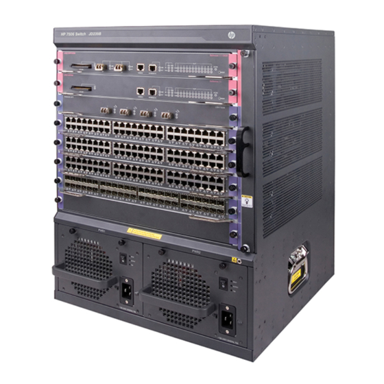
Appendix A Chassis views and technical specifications Chassis views Every 7500 switch chassis has an MPU section, LPU section, power supply section, and fan assembly section. Figure 54 uses the 7503 switch as an example. Figure 54 Front view of the 7503 Table 25 Chassis structure Section Description... -
Page 97: Switch And Fru Aliases
Section Description Ordering remarks Both LPU slots and LPUs are purple edged for easy identification. You must order LPUs as needed and install (2) LPU slots The LPUs are interface cards that provide at least one LPU. network services, including receiving and forwarding traffic. - Page 98 Product code Description Alias HP 7503-S 144 Gbps Fabric / Main Processing Unit with 16 GbE JD222A SFP Ports and 8 GbE Combo Ports LSQ1CGP24TSC0 HP 7503-S 144 Gbps TAA Fabric / Main Processing Unit with 16 JC698A GbE SFP Ports and 8 GbE Combo Ports HP 7500 384 Gbps Fabric / Main Processing Unit with 2 10-GbE JD193B XFP Ports...
- Page 99 Product code Description Alias JF290A HP 7500 8-port 10-GbE SFP+ SC Module LSQ1TGS8SC0 JC723A HP 7500 8-port 10-GbE SFP+ SC TAA-compliant Module HP 7500 20-port Gig-T / 4-port GbE Combo PoE-upgradable SC JC669A LSQ1GV24PSC0 Module JC792A HP 7500 4-port 40GbE QSFP+ SC Module LSQ1QGS4SC0 JG373A HP 7500 4-port 40GbE CFP SC Module...
- Page 100 Table 29 Power supply models Product code Description Alias JD218A HP 7500 1400W AC Power Supply 1400W AC JD208A HP 7500 1400W DC Power Supply 1400W DC JD217A HP 7500 650W AC Power Supply 650W AC JD209A HP 7500 650W DC Power Supply 650W DC JD226A HP 7502 300W AC Power Supply...
-
Page 101: Weights And Dimensions
Table 34 CF card models Product code Description Alias JC686A HP X600 256M Compact Flash Card CF-256M-I JC685A HP X600 512M Compact Flash Card CF-512M JC684A HP X600 1G Compact Flash Card CF-1G Weights and dimensions Table 35 Chassis weights and dimensions Dimensions Model Weight... - Page 102 Dimensions Card model Weight Height Width Depth LSQ1GV24PSA0 2.8 kg (6.17 lb) 40 mm (1.57 in) 399 mm (15.71 in) 352 mm (13.86 in) LSQ1GV48SA0 3.09 kg (6.81 lb) 40 mm (1.57 in) 399 mm (15.71 in) 352 mm (13.86 in) LSQ1GP12SC0 2.66 kg (5.86 lb) 40 mm (1.57 in)
- Page 103 NOTE: The dimensions of the cards are measured as follows: H—Height of the card front panel • W—Width of the card front panel • D—Depth from the card front panel to the connector • Table 37 Power supply weights and dimensions Dimensions Model Weight...
-
Page 104: Module Power Consumption And Total Power Consumption
Module power consumption and total power consumption Total power consumption The total power consumption is the system power consumption plus PoE power consumption. The system power consumption is the sum of the power consumption of all running cards and the •... -
Page 105: Card Power Consumption
NOTE: The PoE power consumption is 0 if the switch does not supply PoE power. • The maximum PoE power consumption refers to the sum of the power consumption of all PDs when all • ports supporting PoE are connected to PDs, and the maximum output power is reached. •... -
Page 106: Fan Assembly Power Consumption
Minimum static power Maximum dynamic power Model consumption consumption LSQ1QGC4SC0 52 W 85 W LSQ1GP24TSD0 47 W 75 W LSQ1GP24TXSD0 54 W 95 W LSQ1GP48SD0 44 W 95 W LSQ1GV48SD0 67 W 95 W LSQ1TGX2SD0 43 W 55 W LSQ1TGX4SD0 53 W 80 W LSQ1TGX8SD0... -
Page 107: Environmental Specifications
80%. Thermal output/hour of the switch is 0.9 × (total power consumption of the cards plus power consumption of the fan assembly)/0.8 × 3.4121. NOTE: For the power consumption of the cards and fan assemblies of the 7500 Switch Series, see "Module •... -
Page 108: Appendix B Frus And Compatibility Matrixes
Appendix B FRUs and compatibility matrixes NOTE: In the compatibility matrixes in this appendix, a solid dot ( ) represents compatible and a dash (—) represents incompatible. MPUs MPUs are the supervisor engines that manage and control the operations of a switch. The MPUs for the 7500 switches also work as switching fabrics. -
Page 109: Lpus
Table 44 MPU and 7500 switch chassis compatibility matrix 7502 7503-S 7503 7506 7510 7506-V LSQ1MPUA0 — — — — — LSQ1CGP24TSC0 — — — — — LSQ1CGV24PSC0 — — — — — LSQ1SRPB0 (Salience — — LSQ1SRPD0 (Salience — —... - Page 110 Interface Available Conn Number of Description transmission transceiver ector interfaces rate modules 48-port Gigabit 10/100/1000 electrical Ethernet LSQ1GV48SA0 RJ-45 Mbps, interface card half/full-duplex (RJ-45)-PoE • Gigabit SFP 12-port Gigabit module optical Ethernet LSQ1GP12SC0 1000/100 Mbps interface card (SFP, • 100-Mbps SFP module •...
- Page 111 Interface Available Conn Number of Description transmission transceiver ector interfaces rate modules 10/100/1000 RJ-45 Mbps, 20-port Gigabit half/full-duplex electrical interface LSQ1GV24PSC0 (RJ-45) + 4-port • Gigabit SFP Gigabit Combo module 1000/100 Mbps interface card-PoE • 100-Mbps SFP module • Gigabit SFP 24-port Gigabit module optical interface (SFP,...
- Page 112 Interface Available Conn Number of Description transmission transceiver ector interfaces rate modules • Gigabit SFP module 16-port Gigabit 1000/100 Mbps • optical Ethernet 100-Mbps interface (SFP, LC) + SFP module LSQ1GP24TXSD 8-port Gigabit combo 10-Gigabit XFP interface + 2-port 10 Gbps module 10-Gigabit optical interface (XFP, LC)
- Page 113 Interface Available Conn Number of Description transmission transceiver ector interfaces rate modules 4-port 10-Gigabit optical Ethernet 10-Gigabit XFP LSQ1TGX4EB0 10 Gbps interface card (XFP, module No greater than One console 115200 bps and port defaults to 9600 HP 10500/7500 20G Unified LSU3WCMD0 RJ-45 Wired-WLAN...
- Page 114 Interface Available Conn Number of Description transmission transceiver ector interfaces rate modules Copper 2 combo port:10/100/10 interfaces,su 00 Mbps, half/full RJ-45 pport duplex +SFP optical-electi Fiber port: rcal Gigabit SFP 1000 Mbps, full switching module duplex No greater than One console 115200 bps and RJ-45 port...
-
Page 115: Power Supplies
Power supplies CAUTION: A chassis must be configured with at least one power supply. To improve power supply availability, you • can configure a chassis with two power supplies, which back up each other. The power supplies installed on an HP 7500 switch must be the same model. •... -
Page 116: Fan Assembly
NOTE: The rack unit (RU) specifies the rack height, and 1 RU is 44.45 mm (1.75 inch). Make sure the total maximum output power of the ordered power supplies is greater than the overall • power consumption. HP recommends that you reserve 20% of the maximum output power. If the switch is expected to supply power for attached devices through PoE, order a power supply •... -
Page 117: Mounting Accessories
Fan assembly Number of fans Fan diameter Max rotating speed Max airflow 7506-V fan 120 mm (4.72 in) 3200 RPM 546 CFM assembly 7510 fan 92 mm (3.62 in)/120 3800 RPM/3100 RPM 662 CFM assembly mm (4.72 in) • The fans on the 7503-S fan assembly rotate at a fixed speed and cannot automatically adapt to the ventilation condition. -
Page 118: Cf Cards
PoE-capable LPU PoE-capable ports Compatible PoE DIMM modules PoE standard LSQ3GV48SC0 LSQ1CGV24PSC0 LSQ1GV24PSC0 HP 7500 24-port PoE DIMM(JC671A) Type 1 LSQ1GV24PSA0 LSQ1FV48SA0 LSQ1GV48SA0 HP 7500 48-port PoE DIMM(JD192B) Type 1 LSQ1GV48SC0 LSQ1GV40PSC0 HP 7500 48-port PoE DIMM (JD192B) Type 1 NOTE: Type 1—A port outputs 0 to 15.4 W of power at 44 V to 57 V, and the maximum current is 350 mA. - Page 119 Gigabit SFP transceiver modules (Table • • 100-Mbps SFP transceiver modules (Table 59) available for the 7500 switches Table 51 CFP module specifications Maximum Central Fiber Product code Description transmission wavelength(nm) diameter (μm) distance HP X140 40G CFP LC LR4 10 km (6.21 JC857A 1310...
- Page 120 Table 55 XFP modules available for the 7500 switches Multimode Central Fiber fiber modal Product Max transmission wavelength Description diameter bandwidth Code distance (μm) (nm) (MHz*km) 2000 300 m (984.25 ft) 50/125 82 m(269.03 ft) HP X130 10G XFP LC SR JD117B 66 m(216.54 ft) Transceiver...
- Page 121 Table 56 SFP+ modules available for the 7500 switches Multimode Central Maximum fiber modal Product Fiber wavelength Description transmission bandwidth Code diameter (μm) distance (nm) (MHz*km) 2000 300 m (984.25 ft) 50/125 82 m (269.03 ft) HP X130 10G SFP+ JD092B 66 m (216.54 ft) LC SR Transceiver...
- Page 122 Multimode Central Fiber Maximum fiber modal Product wavelength Description diameter transmission bandwidth Code (μm) distance (nm) (MHz*km) 550 m (1804.46 ft) 50/125 500 m (1640.42 ft) HP X120 1G SFP LC SX JD118B Transceiver 275 m (902.23 ft) 62.5/125 220 m (721.78 ft) 9/125 10 km (6.21 miles) HP X120 1G SFP LC LX...
- Page 123 Multimode Central Fiber Maximum fiber modal Product wavelength Description diameter transmission bandwidth Code (μm) distance (nm) (MHz*km) HP X170 1G SFP LC JD112A 1610 9/125 70 km (43.50 miles) LH70 1610 Transceiver NOTE: The 100/1000-Mbps SFP port of a combo interface does not support transceiver module JD089B. Table 59 100-Mbps SFP modules available for the 7500 switches Central Maximum...
-
Page 124: Appendix C Leds
Appendix C LEDs The HP 7500 Switch Series provides various LEDs for you to check the status of MPUs, LPUs, and power supplies. Table 60 shows the supported LEDs. NOTE: The HP 7500 Switch Series supports various MPU and LPU models. The type and quantity of LEDs vary by MPU and LPU models. -
Page 125: Mpu Leds
MPU LEDs Figure 55 MPU LEDs (LSQ1SRP2XB0 as an illustration) (1) CF card status LED (2) XFP port LEDs (3) Management Ethernet port LEDs (4) Power and fan status LEDs (5) Card status LEDs (6) MPU active/standby status LED Management Ethernet port LEDs The MPU has one LINK LED and one ACT LED to indicate the link status and data forwarding status of the management Ethernet port. - Page 126 Table 63 Description for PWR LEDs with numbers FAIL Description The corresponding power supply is operating correctly. The corresponding power supply has no output power. (The cause can be: the power supply is faulty or not switched on; a power cord connection problem has occurred;...
- Page 127 NOTE: A quick flashing RUN LED indicates that the card is in the process of startup rather than operating correctly. The ALM LED will be on for a period of time at the initial phase of the system startup. MPU active/standby status LED (ACTIVE) The MPUs provide the active/standby status LED (ACTIVE) to indicate the status (active or standby) of the MPUs.
-
Page 128: Lpu Leds
Table 69 Combo interface status LED description LED status Description Flashing The combo interface is receiving or sending data. Combo interface A link is present. status LED No link is present. NOTE: For the SFP port and the RJ-45 Ethernet port of a combo port, only one port can be active at a time. The •... - Page 129 RJ-45 Ethernet port LED The LPUs provide RJ-45 Ethernet port LEDs to indicate the link status and data receiving/forwarding status of the corresponding Ethernet ports. Table 72 RJ-45 Ethernet port LED description LED status Description Flashing The Ethernet port is receiving or sending data. RJ-45 Ethernet port LED A link is present.
-
Page 130: Power Supply Leds
Table 75 SFP+ port LED description LINK Description Flashing A link is present, and the SFP+ port is receiving or sending data. A link is present, but no data is being received or sent. No link is present. XFP port LEDs The LPUs provide XFP port LEDs to indicate the link status and data receiving/forwarding status of the corresponding XFP port . - Page 131 300W AC/300W DC power supply status LED The 300W AC/300W DC power supply provides a red-green status LED. Table 79 300W AC/300W DC power supply status LED description Status Description Analysis The power supply is Green operating correctly. This status has occurred in the following cases: •...
- Page 132 Table 81 1400W AC power supply status LED description Status Description Analysis The power is input Green correctly. A power input problem has The input voltage is not in the rated voltage range. occurred. INPUT This status has occurred in the following cases: •...
- Page 133 Status Description Analysis This status has occurred in the following cases: • The power supply is faulty. • A power cord connection problem has No power is input. occurred. • The external power supply is unavailable. • The system power output switch is not turned on. The power is output Green correctly.
- Page 134 Table 83 2800W AC power supply status LED description Status Description Analysis The power is input Green correctly. A power input problem The input voltage is not in the rated voltage range. has occurred. INPUT This status has occurred in the following cases: •...
- Page 135 Status Description Analysis The PoE power is output Green correctly. This status has occurred in the following cases: • A PoE power output The PoE output voltage is not in the rated problem has occurred. voltage range. • The PoE power switch is not turned on. PoE OUTPUT This status has occurred in the following cases: •...
- Page 136 Status Description Analysis The fans are operating Green correctly. This status has occurred in the following cases: The fans are operating • A fan failure has occurred. incorrectly. • The system power switch is not turned on. SYS FAN This status has occurred in the following cases: •...
- Page 137 Status Description Analysis The PoE power is output Green correctly. This status has occurred in the following cases: • The power supply generates an alarm due to A PoE power output output short-circuit, output over-current, output problem has occurred. over-voltage, or over temperature, and enters the protection state.
-
Page 138: Appendix D Cables
Appendix D Cables This chapter describes the cables available for connecting ports on MPUs and LPUs. Table 85 Cable description Cable Port type Application Ethernet twisted pair cable RJ-45 Ethernet ports Connects RJ-45 Ethernet ports to transmit data XFP/SFP+/SFP/CFP/QSFP+ Optical fiber Connects the fiber ports to transmit data ports SFP+ cable... -
Page 139: Cable Type
Standard 568B—pin 1: white/orange stripe, pin 2: orange solid, pin 3: white/green stripe, pin 4: • blue solid, pin 5: white/blue stripe, pin 6: green solid, pin 7: white/brown stripe, pin 8: brown solid. Cable type Based on performance Ethernet cables can be classified into category 3, category 4, category 5, category 5e, category 6, and category 7 cable based on performance. -
Page 140: Pin Assignments
Figure 58 Straight-through cable Figure 59 Crossover cable Pin assignments Select an Ethernet twisted pair cable according to the RJ-45 Ethernet interface type on your device. An RJ-45 Ethernet interface can be MDI (for routers and PCs) or MDIX (for switches). For the pinouts of RJ-45 Ethernet interfaces, see Table 87 Table... -
Page 141: Making An Ethernet Twisted Pair Cable
Table 87 RJ-45 MDI interface pinouts 10Base-T/100Base-TX 1000Base-T Signal Function Signal Function Send data BIDA+ Bi-directional data cable A+ Send data BIDA- Bi-directional data cable A- Receive data BIDB+ Bi-directional data cable B+ Reserved BIDC+ Bi-directional data cable C+ Reserved BIDC- Bi-directional data cable C- Receive data... -
Page 142: Optical Fiber
Cut the top of the wires even with one another. Insert the wires into the RJ-45 end and make sure the wires extend to the front of the RJ-45 end and make good contact with the metal contacts in the RJ-45 end and in the correct order. -
Page 143: Usage Guidelines
Pigtail cord A pigtail cord is an optical fiber that has an optical connector on one end and a length of exposed fiber on the other. The end of the pigtail is fusion spliced to a fiber, connecting the fiber cable and transceiver. Pigtail cords fall into single-mode (yellow) and multi-mode (orange), and can also be classified into SC, LC, FC, and so on based on interface type. -
Page 144: Sfp+ Cable
If the fiber has to pass through a metallic board hole, the hole must have a sleek and fully filleted • surface (the filleting radius must be not less than 2 mm). When passing through a metallic board hole or bending along the acute side of mechanical parts, the fiber must wear jackets or cushions. •... - Page 145 Figure 64 QSFP+ to SFP+ cable (1) QSFP+ connector (2) QSFP+ pull latch (3) SFP+ connector (4) SFP+ pull latch...
-
Page 146: Appendix E Cabling Recommendations
Appendix E Cabling recommendations When an HP 7500 switch is mounted in a 19 inch standard rack, the interface cables are routed through the cable management brackets, bound at cabling racks on chassis sides, and then routed up or down to pass through the chassis top or the raised floor, depending on the available equipment room condition. -
Page 147: Cable Management Requirements
Cable management requirements Bind and put the cables inside the rack in an organized manner. Make sure the cables do not have • any kinks or sharp bends. Figure 65 Cable binding example 1 Different cables (power, signal, and PGND cables) should be routed and bound separately rather •... - Page 148 Figure 67 Cable binding example 3 The spare cables or excessive cable parts should be folded and bound and placed at a right place • in the rack or on the cable routing slot. A "right place" refers to the place where the cables will not affect the operation of the switch or impair the switch, or be damaged.
- Page 149 Table 90 Tie-binding parameters Cable bundle diameter (mm) Space between bundles (mm) 80 to 150 10 to 30 150 to 200 200 to 300 No cable or bundle can tie a knot. • • The metal parts of the crimped cold-pressed terminal blocks (such as air switch) cannot stretch beyond the blocks.
-
Page 150: Index
Index A C D E F G I L M N O P Q R S T V W Installing a CF card to an MPU (optional),37 Installing a power supply,22 Accessing the switch for the first time,45 Installing a transceiver module (optional),38 Attaching an ESD wrist strap,20... - Page 151 Related information,87 Replacing a card,80 Testing connectivity,54 Replacing a CF card,84 Thermal output,100 Replacing a fan assembly,81 Transceiver modules,1 12 Replacing a power supply,79 Troubleshooting methods,74 Replacing a transceiver module,85 Troubleshooting the system,74 Replacing the PoE DIMM,86 Verifying and diagnosing transceiver modules,67 Safety recommendations,1...