Table of Contents
Advertisement
Advertisement
Table of Contents

Related Manuals for Humminbird LCR 400 ID


Summary of Contents for Humminbird LCR 400 ID
-
Page 2: Table Of Contents
INSTALLATION PREPARATION………………………………………………………. 2 Parts Supplied……………………………………………………………………. 2 Accessories………………………………………………………………………. 2 Installation Overview……………………………………………………………. 2 Alternative Transducers and Mounting Methods…………………………….. Transducer Exchange…………………………………………………………… 5 INSTALLATION………………………………………………………………………….. 6 Transom Installation…………………………………………………………….. 6 Inside the Hull Installation………………………………………………………. 10 Control Head Installation……………………………………………………….. 12 Test the Installation……………………………………………………………… 15 BEFORE BEGINNING………………………………………………………………….. 16 USING THE LCR400ID …………………………………………………………………... -
Page 3: Installation
TRANSDUCER MOUNTING PROCEDURE Humminbird’s high-speed transducer is supplied with your LCR. This transducer has been designed to give good high speed readings on most all boat designs, including aluminum. Please carefully consider the following before installing your transducer. TRANSDUCER MOUNTING OPTIONS A. - Page 4 B. Inside Hull Mount- The high speed transducer can be mounted inside the hull (without pivot assembly) using the proper two-part epoxy, such as Humminbird’s epoxy kit. Even though there is some loss of signal in shooting through the hull, your LCR will perform well with this type of installation.
- Page 5 aluminum boat locate the template on the transom between rows of rivets, or ribs that are on the bottom of the boat. Align the template so that the bottom corner of the template nearest the center of the transom is on the bottom edge of the transom. Once the location is determined mark and drill three 7/64”...
- Page 6 NOTE: On boats with more than 15 degree deadrise angle it may be necessary to mount the transducer slightly off parallel with the water level. (See Figure E) Mark and drill the three 9/64” dia. holes as shown on the template. Attach the metal bracket using the three #10 self threading screws supplied.
-
Page 7: Inside The Hull Installation
Step 4 TRANSDUCER ASSEMBLY- Insert the transducer assembly into the metal bracket from the bottom. Push up until the holes in the plastic pivot align with the uppermost holes in the bracket. Slide the O-ring on to the headed pin and insert it through the two parts. - Page 8 For this reason, Techsonic Industries, Inc. will not be responsible for any damage due to the mounting of your transducer in this manner. NOTE: An Epoxy Kit (Part N. EPK) is available from Humminbird. This Epoxy Kit has been formulated for Inside Hull Transducer Installation.
-
Page 9: Control Head Installation
7. Remove the water and transducer and clean the marked area and the bottom of the transducer thoroughly. 8. Using the Humminbird Epoxy Kit or equivalent, mix an ample amount of epoxy without causing it to bubble and pour it in the area the transducer is to be mounted. - Page 10 Position the swivel base and drill four ¼” diameter holes. Note: The LCR hole pattern Is the same as for all Humminbird flasher units. Use hardware provided to mount this base to the boat. Next place the gimbal bracket on the swivel base and attach with four small machine screws, provided.
- Page 11 INSTALLING THE CABLES Your LCR comes equipped with Humminbird’s new Angle-Lock power and transducer connectors. The power connector is identified with the letter P on the back of the plug.
-
Page 12: Test The Installation
“Transducer”. Note: An adapter (AD-4) is available to allow use of an old waterproof (BNC) transducer with the LCR, but be sure that the transducer is a 16degree. A 32- degree transducer cannot be used. A 11/8” hole must be drilled to pull through the transducer connector. After drilling the hole, pull the transducer connector up through the hole. - Page 13 you will install on the transom or inside the hull, and the LCR 400ID unit which you will mount with the supplied gimbal bracket. The transducer and LCR 400ID communicate by means of a cable, and are powered by your boat’s 12-volt DC battery. The transducer and LCR 400ID use the basic principles of sonar to reveal objects beneath the water's surface.
- Page 14 – your LCR 400ID will provide you with many years of thoroughly reliable operation. In the unlikely event that your Humminbird does require repairs, we offer an exclusive Service Guarantee – free of charge during the first year after purchase, and available at a reasonable rate after the one-year warranty period.
-
Page 15: Using The Lcr400Id
USING THE LCR400ID USING THE BUILT-IN SIMULATOR USING THE LCR400ID This section provides complete information on operating the LCR 400ID through its front panel controls. You are encouraged to read this information completely as you first learn to use the LCR 400ID. -
Page 16: Front Panel Buttons
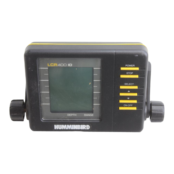
FRONT PANEL BUTTONS The LCR 400ID offers several functions that you can adjust with the front panel buttons. (Note that to select something with a button, you must press it fully so that you hear a “chirp” sound). You can get acquainted with these features by actual operation, or when using the simulator. -
Page 17: Functions
USING THE LCR400ID OPERATING THE LCR400ID SENSITIVITY 1. Selecting Sensitivity/Units; Factory setting: +0/FEET The Sensitivity/Units function has two uses: It lets you adjust LCR 400ID sensitivity and controls whether depth measurement is in feet or fathoms. The LCR 400ID automatically increases or decreases its sensitivity setting when water conditions change (as when the bottom is stirred up). - Page 18 USING THE LCR400ID OPERATING THE LCR400ID FISH ALARM 3. Enabling Fish Alarm; Factory Setting: OFF The Fish Alarm alerts you with a chirping sound whenever the LCR 400ID detects fish (or another object not attached to the bottom). To activate it, select FISH ALM and press the ON-OFF button.
- Page 19 USING THE LCR400ID OPERATING THE LCR400ID BOTTOM LOCK 5. Using Bottom-Lock; Factory Setting: OFF Bottom-lock provides an up-close view like Zoom, except that in this case the zoomed view automatically moves up or down to stay on the bottom. To use this feature, select BTM LOCK and press ON-OFF.
- Page 20 USING THE LCR400ID OPERATING THE LCR400ID DEPTH RANGE 7. Setting Depth Range; Factory Setting: On (Automatic) When you turn the LCR 400ID on, it finds the bottom, sets the ideal depth range, and automatically adjusts the depth range (to as much as 480’) as the depth changes.
-
Page 21: Specifications
Operating Frequency Power Requirements Power Cable Length Standard Unit Portable Unit Transducer: Standard Portable Transducer Cone Angle Depth Ranges Zoom Ranges Unit Construction Unit Dimensions Display Viewing Area Matrix Configuration SPECIFICATIONS 200 KHz 10-16 Volts 48” Non-replaceable XHS-6-16 XPT-6-16 16 degrees 0 to 15’, 30’, 60’, 120’, 180’, 240’, 360’, or 480’... -
Page 22: Maintenance And Warranty
MAINTENANCE AND WARRANTY MAINTENANCE Your Humminbird fishfinder is designed to provide years of trouble free operation with virtually no maintenance. Follow these simple procedures to ensure your Humminbird continues to deliver top performance. If the unit comes into contact with salt spray simply wipe the affected surfaces with a cloth dampened in fresh water. -
Page 23: Troubleshooting
Repairs should be performed only by authorized Humminbird technicians. Many requests for repair received by Humminbird involve units that do not actually reed repair. These units are returned “no problem found.” If you have a problem with your Humminbird, use the following troubleshooting guide before calling Customer Support or sending your unit in for repair. - Page 24 4. When in very shallow water, I get gaps in the bottom reading and inconsistent digital depth indication. Your Humminbird fishfinder will work reliably in water 2’ (.6m) or deeper. The depth is measured from the transducer, not necessarily from the surface.
- Page 25 7. My unit loses power at high speeds. Most Humminbird fishfinders have over-voltage protection that turns the unit off when input voltage exceeds 20 VDC. Some outboard motors do not effectively regulate the power output of the engine's alternator and can produce voltage in excess of 20 volts when running at high RPMs.
-
Page 26: Warranty
Humminbird reserves the right to perform modifications or improvement on its products without incurring the obligation to install the changes on units previously manufactured, sold, delivered, or serviced. -
Page 27: Service Policy
SERVICE POLICY SERVICE POLICY This Service Policy is valid in the United States only. This applies to Humminbird units returned to our factory in Eufaula, Alabama, and is subject to change without notice. All repair work is performed by factory-trained technicians to meet exacting factory specifications. -
Page 28: Customer Support
CUSTOMER SUPPORT CUSTOMER SUPPORT If you have any questions, call our Humminbird Customer Support Hotline: 1-334-687-0503 Throughout the U.S. and Canada, hours are Monday-Friday, 8:00 a.m. to 5:00 p.m. Central time. If after reading “Troubleshooting” you determine your unit needs factory service, please attach a description of the problem and send it with the unit to the address below.