Advertisement
Table of Contents
- 1 Installation Preparation
- 2 Parts Supplied
- 3 Installation Overview
- 4 Alternate Mounting Methods
- 5 Transducer Exchange
- 6 Beginning Installation
- 7 Transom Installation
- 8 Inside the Hull Installation
- 9 Control Head Installation
- 10 Test the Installation
- 11 Testing the Installation
- 12 What You See On-Screen
- 13 Control Functions
- Download this manual
Advertisement
Table of Contents

Related Manuals for Humminbird LCR W


Summary of Contents for Humminbird LCR W
-
Page 2: Installation Preparation
Customer Support section. INSTALLATION OVERVIEW Your Humminbird fishfinder consists of two primary components to install: the control head and the transducer. The control head contains the sonar transmit and receive circuitry, as well as the user controls and display. - Page 3 INSTALLATION PREPARATION INSTALLATION OVERVIEW Determining How to Mount the Transducer Your Humminbird fishfinder includes a standard transducer. This transducer can be mounted on the transom of the boat or bonded to the inside of a fiberglass hull boat. The transom installation, which is the most widely used, places the transducer on the outside of the boat hull.
-
Page 4: Alternate Mounting Methods
ALTERNATE MOUNTING METHODS ALTERNATE TRANSDUCERS AND MOUNTING METHODS Your Humminbird fishfinder comes with everything necessary for installation and operation on most boats. However, there are several situations which may require a different type of transducer. Inboard boats, wood or metal hulls, and sail boats create unique transducer mounting needs Alternate transducers and mounting methods are detailed below. -
Page 5: Transducer Exchange
BEGINNING INSTALLATION Now that you have determined the transducer mounting method you can begin installation of your new Humminbird fishfinder. The installation guide included on the next few pages provides detailed step by step instructions for installation of the control head and transducer. For transom mount transducer installations you will need the mounting template included with your manual. -
Page 6: Transom Installation
INSTALLATION TRANSOM INSTALLATION Do not begin this transducer installation until you read the Installation Preparation in the Operation Guide. This chapter contains information critical to the correct installation of your transducer. Due to the wide variety of boat hulls, only general instructions are presented in the installation guide. - Page 7 INSTALLATION TRANSOM INSTALLATION If the propeller(s) is (are) forward of the transom, it may be impossible to find an area clear from turbulence, and a different mounting technique or transducer type should be considered. Step Two - Drill the Mounting Holes 1.
- Page 9 INSTALLATION TRANSOM INSTALLATION Step Four - Mount the Transducer to the Transom 1. Apply silicone sealant to the mounting holes drilled into the transom. 2. Align the transducer assembly with the drilled holes in the transom (Figure 8). 3. Use either a flat head screwdriver, a 5/16" (8mm) hex driver, or a 5/16" (8mm) socket to mount the assembly.
- Page 10 mounting bracket. Drill this hole and install the screw after final testing and adjustments have been completed.
- Page 11 If the cable is too short, extension cables are available to extend the transducer cable up to a total of 50' (15 m). Call Humminbird Customer Support for more information. Follow these steps to route the cable through the transom: 1.
-
Page 12: Inside The Hull Installation
Inside the hull mounting generally produces good results in single thickness fiberglass-hulled boats. Humminbird cannot guarantee depth performance when transmitting and receiving through the hull of the boat since some signal loss occurs. The amount of loss depends on hull construction and thickness, and the installation. - Page 13 The transducer cannot transmit through air. The water purges any air from between the transducer and the hull and fills any voids in the coarse fiberglass surface.
- Page 14 INSTALLATION INSIDE THE HULL INSTALLATION 3. Power up the Control Head. 4. Run the boat at various speeds and water depths while observing the screen on the Control Head. If the unit functions well at low speeds but begins to skip or miss the bottom at higher speeds, the transducer needs to be moved.
-
Page 15: Control Head Installation
INSTALLATION CONTROL HEAD INSTALLATION CONTROL HEAD INSTALLATION Step One - Determine Where to Mount Begin the installation by determining where to mount the control head. Consider the following to determine best location: The cables for power, transducer and temp/speed accessories (if applicable) should be installed first and must reach the mounting location. - Page 16 fuse in the connection. If you must wire the control head directly to a battery, be sure to install an inline fuse holder...
- Page 17 CONTROL HEAD INSTALLATION and one amp fuse (not included) for the protection of the unit (Figure 21). Humminbird is not responsible for over voltage or over current failures. In order to minimize the potential for interference with other marine electronics a separate power source (such as a second battery) may be necessary.
- Page 18 Optional: If the cables pass outside the mounting bracket, install the hole cover over the hole and fasten in place using the two #8 x 7/8” (22mm) wood screws (Figure 24).
- Page 19 5. Install the control head by sliding it onto the mounting bracket until it is fully seated. To remove the unit simply depress the latch on the rear of the unit and lift (Figure 29). Your Humminbird is now ready for operation.
-
Page 20: Test The Installation
Note: it is often necessary to make several incremental transducer adjustments before optimum high-speed performance is achieved. Important: For Transom Mount transducer installations, install the third mounting screw after the final transducer adjustments. Humminbird 3 Humminbird Lane Eufaula, Alabama 36027... - Page 21 • Any VHF radio you have may incur some degree of interference with the depth sounder. Humminbird depthsounders are designed to minimize this interference; however it is best to route the transducer cable and antenna cable as far away from each other as possible, for example, on opposite sides of the boat.
-
Page 22: Testing The Installation
Increase your boat speed to ensure that the transducer remains in contact with turbulence-free water at higher boat speeds. All Humminbird depthsounders are designed to work at speeds of 70 MPH or more, however, use caution when operating any boat at high speed. - Page 23 USING THE LCR W The LCR W is easy to use. Simply press the POWER button, and the unit will automatically locate the bottom, adjust the depth range and sensitivity to an appropriate level, and draw a picture of the terrain beneath your boat. If POWER is the only button you press, you will benefit from the advanced automatic bottom tracking capability of the unit.
-
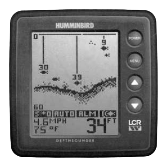
Page 24: What You See On-Screen
WHAT YOU SEE ON-SCREEN The first thing you may notice about the LCR W unit is the high resolution screen LCD display. The LCD display uses super-twist technology, for maximum viewability and is ruggedized for tough shock and vibration endurance. The display can operate at temperatures more extreme than you are likely to encounter. - Page 25 return, in varying densities of pixelization. This bottom depiction is useful in locating structure, by comparing relative density as well as depth. The transmitted sonar signal travels downward, and is reflected back toward the surface by the bottom or other objects for display on-screen. The signal does not stop there - it is reflected downward again by the surface of the water, and a weak "second return"...
-
Page 26: Control Functions
CONTROL FUNCTIONS The LCR W unit uses only four buttons to control all functions. When any button is pressed, an audible "chirp" will verify the control input. POWER, as previously discussed, powers the LCR W for normal operation. Also, if the unit is powered off, press and hold POWER until you hear a continuous "chirp"... - Page 27 A setting of -2 sets the sensitivity two steps below what the unit would normally select, so only the largest targets or other returns are displayed. The LCR W adjusts the depth range automatically, so the bottom return is displayed at the bottom 1/3 of the display.
- Page 28 Zoom Another form of range control is Zoom. Zoom allows selection of various ranges for full screen viewing. By using the display to view a smaller area, the effective display resolution is increased, and the units ability to separate targets close together is enhanced. The zoom range is determined by the depth range in use when Zoom is enabled.
- Page 29 Fish Alarm The Fish Alarm alerts you to the presence of fish, or other targets not attached to the bottom, in the water beneath your boat. The Fish Alarm has 3 different settings which correspond to the 3 different size fish targets shown on-screen. To enable Fish Alarm, use the UP and DOWN arrow buttons to adjust the size return you want to be alerted to: large fish only, large and medium size fish, or all fish.
- Page 30 ID "Off" disables the units interpretation of targets, and displays the "raw" sonar information as it is received. Turning ID off also disables the fish alarm. Advanced users may prefer this type of presentation, so they can make their own interpretation from the information displayed.