Table of Contents
Advertisement
Advertisement
Table of Contents

Related Manuals for Humminbird LCR 4000


Summary of Contents for Humminbird LCR 4000
-
Page 2: Table Of Contents
Transom Installation…………………………………………………………….. 6 Inside the Hull Installation………………………………………………………. 10 Control Head Installation……………………………………………………….. 12 Test the Installation……………………………………………………………… 15 INTRODUCTION………….…...………………………………………………………... 16 USING THE LCR 4000………………………………………………………………….. 19 Total Screen Update ………………………………………………………….. 19 Operational Instructions………………………………………………………… 21 Learning to Use Your LCR……..……………...………………………………. Learning to Read the Display.…………………………………………………. 31 MAINTENANCE AND WARRANTY………………………………………………….. -
Page 3: Transducer Exchange
TRANSDUCER MOUNTING PROCEDURE Humminbird’s high-speed transducer is supplied with your LCR. This transducer has been designed to give good high speed readings on most all boat designs, including aluminum. Please carefully consider the following before installing your transducer. TRANSDUCER MOUNTING OPTIONS A. -
Page 4: Transom Installation
B. Inside Hull Mount- The high speed transducer can be mounted inside the hull (without pivot assembly) using the proper two-part epoxy, such as Humminbird’s epoxy kit. Even though there is some loss of signal in shooting through the hull, your LCR will perform well with this type of installation. - Page 5 aluminum boat locate the template on the transom between rows of rivets, or ribs that are on the bottom of the boat. Align the template so that the bottom corner of the template nearest the center of the transom is on the bottom edge of the transom. Once the location is determined mark and drill three 7/64”...
- Page 6 NOTE: On boats with more than 15 degree deadrise angle it may be necessary to mount the transducer slightly off parallel with the water level. (See Figure E) Mark and drill the three 9/64” dia. holes as shown on the template. Attach the metal bracket using the three #10 self threading screws supplied.
- Page 7 Step 4 TRANSDUCER ASSEMBLY- Insert the transducer assembly into the metal bracket from the bottom. Push up until the holes in the plastic pivot align with the uppermost holes in the bracket. Slide the O-ring on to the headed pin and insert it through the two parts.
-
Page 8: Inside The Hull Installation
For this reason, Techsonic Industries, Inc. will not be responsible for any damage due to the mounting of your transducer in this manner. NOTE: An Epoxy Kit (Part N. EPK) is available from Humminbird. This Epoxy Kit has been formulated for Inside Hull Transducer Installation. - Page 9 7. Remove the water and transducer and clean the marked area and the bottom of the transducer thoroughly. 8. Using the Humminbird Epoxy Kit or equivalent, mix an ample amount of epoxy without causing it to bubble and pour it in the area the transducer is to be mounted.
-
Page 10: Control Head Installation
Position the swivel base and drill four ¼” diameter holes. Note: The LCR hole pattern Is the same as for all Humminbird flasher units. Use hardware provided to mount this base to the boat. Next place the gimbal bracket on the swivel base and attach with four small machine screws, provided. - Page 11 INSTALLING THE CABLES Your LCR comes equipped with Humminbird’s new Angle-Lock power and transducer connectors. The power connector is identified with the letter P on the back of the plug.
- Page 12 “Transducer”. Note: An adapter (AD-4) is available to allow use of an old waterproof (BNC) transducer with the LCR, but be sure that the transducer is a 16degree. A 32- degree transducer cannot be used. A 11/8” hole must be drilled to pull through the transducer connector. After drilling the hole, pull the transducer connector up through the hole.
-
Page 13: Installation
Note: it is often necessary to make several incremental transducer adjustments before optimum high-speed performance is achieved. Important: For Transom Mount transducer installations, install the third mounting screw after the final transducer adjustments. Humminbird 3 Humminbird Lane Eufaula, Alabama 36027... -
Page 14: Introduction
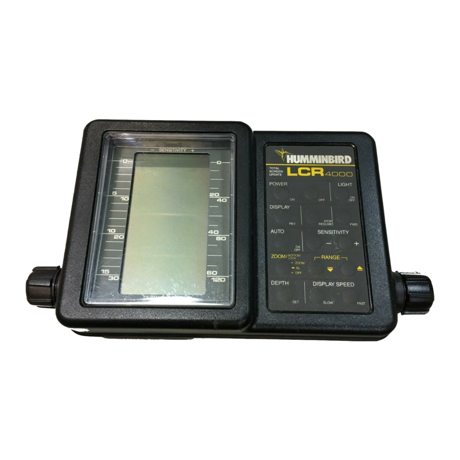
USING THE LCR 4000 INTRODUCTION Before attempting to install or operate your Humminbird LCR, it is recommended that you read the operations manual thoroughly. The LCR is a totally new concept in sonar and has a number of special features not found on any other recorder. To completely understand all the features of your unit, we suggest you follow the instructions set forth in this manual. -
Page 15: Using The Lcr 4000
THEORY OF OPERATION Your new LCR is covered by our Lifetime Guaranteed Service policy. We wish you good luck, good fishing, and many hours of pleasure with your new Humminbird LCR. THEORY OF OPERATION Your Humminbird LCR works on the basic principals of sonar. - Page 16 USING THE LCR 4000 THEORY OF OPERATION The LCR 4000 is designed to operate with a standard 16 transducer included with the unit. Other transducers, such as 32 , cannot be used. In order for your LCR to operate well at high speeds, you must have a properly mounted transducer. Please read the...
-
Page 17: Using The Lcr 4000
USING THE LCR 4000 TOTAL SCREEN UPDATE TOTAL SCREEN UPDATE® What is Total Screen Update? Total screen update is a unique feature of the LCR4000. It will allow you, when changing depth scales, to totally change or update the screen to the new depth scale. It will allow you to zoom in and look at information in much finer detail even after you’ve... - Page 18 USING THE LCR 4000 TOTAL SCREEN UPDATE How To Use Total Screen Update This is the easiest part. Since the LCR’s computer is doing all the work, you will find the LCR4000’s Total Screen Update very easy to use. There are three ways that you will use Total Screen Update: 1.
-
Page 19: Operational Instructions
OPERATIONAL INSTRUCTIONS OPERATIONAL INSTRUCTIONS FOR LCR4000 The Humminbird LCR4000 will operate fully automatic or manual at the discretion of the operator. At the heart of the LCR is a microcomputer which is making thousands of decisions every second. With the LCR4000'S automatic features you will quickly and easily learn the basics of operating your unit, and after a couple of trips on the water you'll be operating the LCR4000 like an expert. - Page 20 USING THE LCR 4000 OPERATIONAL INSTRUCTIONS You may also manually change the depth scale by pressing the depth set button. Each time this button is depressed, the range is decreased by one setting. For example, if you are on the 0-30 ft scale, pressing the depth set button once will change the scale to 0-15 ft.
- Page 21 (See Figure 15). USING THE LCR 4000 OPERATIONAL INSTRUCTIONS indicating more sensitivity. In shallow water or when a hard bottom is being read, the sensitivity needed to achieve a good return will be less.
- Page 22 USING THE LCR 4000 OPERATIONAL INSTRUCTIONS Note: You will find the manual sensitivity control more useful when looking for smaller targets such as smaller fish. In the automatic mode the computer might not be using enough sensitivity to show smaller targets. At higher sensitivity more targets will be seen.
- Page 23 USING THE LCR 4000 OPERATIONAL INSTRUCTIONS To begin transmitting and receiving of new information after using Reverse or Forward, simply press the Stop/Resume button. The display will change back to the location seen before reversing and the unit will resume reading at the immediate point at which the boast is sitting in the water.
- Page 24 USING THE LCR 4000 OPERATIONAL INSTRUCTIONS The Zoom may be activated at any time (during normal transmitting and receiving or stop action, or reverse), but while learning to use the Zoom feature you might find it easiest to first press the Stop/Resume button to freeze the display. Now you can position the Zoom Range, activate the Zoom, and study the display.
- Page 25 USING THE LCR 4000 OPERATIONAL INSTRUCTIONS In bottom lock the expanded information always comes onto the screen at the same location. However, as the information moves across the screen and as the bottom contour moves up or down, the displayed information will also move so that you can see the actual bottom contour.
- Page 26 In order for your LCR to operate well at high speeds, you must have a properly mounted transducer. Please read the transducer mounting procedure carefully. The transducer for the LCR4000 is a l6 just like most standard Humminbird flasher units. Other transducers, such as 32 , cannot be used.
-
Page 27: Learning To Use Your Lcr
USING THE LCR 4000 LEARNING TO USE YOUR LCR LEARNING TO USE YOUR LCR After installing the unit, transducer, and power cable as instructed, the LCR is ready for use. By following the steps below you will be able to quickly learn how to use the LCR. - Page 28 USING THE LCR 4000 LEARNING TO USE YOUR LCR Step 3 Press the depth set button once to change to the next lowest scale. If the bottom is deeper than this scale, the computer will automatically change back to the proper scale.
-
Page 29: Learning To Read The Display
USING THE LCR 4000 LEARNING TO USE YOUR LCR Step 8 Steps 1 through 7 have verified that your LCR is working properly. You are now ready to increase boat speed to test the transducer installation. As you increase boat speed the LCR should give a continuous bottom return. - Page 30 USING THE LCR 4000 LEARNING TO READ THE DISPLAY Brush or thick standing timber will appear as a thick mass with...
- Page 31 LCR then you’re on your way toward gaining the experience you need. USING THE LCR 4000 LEARNING TO READ THE DISPLAY With Zoom activated the two objects close to the bottom on 0-60 ft scale can now be seen as fish off...
-
Page 32: Maintenance And Warranty
MAINTENANCE AND WARRANTY MAINTENANCE Your Humminbird fishfinder is designed to provide years of trouble free operation with virtually no maintenance. Follow these simple procedures to ensure your Humminbird continues to deliver top performance. If the unit comes into contact with salt spray simply wipe the affected surfaces with a cloth dampened in fresh water. -
Page 33: Troubleshooting
Repairs should be performed only by authorized Humminbird technicians. Many requests for repair received by Humminbird involve units that do not actually reed repair. These units are returned “no problem found.” If you have a problem with your Humminbird, use the following troubleshooting guide before calling Customer Support or sending your unit in for repair. - Page 34 4. When in very shallow water, I get gaps in the bottom reading and inconsistent digital depth indication. Your Humminbird fishfinder will work reliably in water 2’ (.6m) or deeper. The depth is measured from the transducer, not necessarily from the surface.
- Page 35 7. My unit loses power at high speeds. Most Humminbird fishfinders have over-voltage protection that turns the unit off when input voltage exceeds 20 VDC. Some outboard motors do not effectively regulate the power output of the engine's alternator and can produce voltage in excess of 20 volts when running at high RPMs.
-
Page 36: Accessories
Humminbird reserves the right to perform modifications or improvement on its products without incurring the obligation to install the changes on units previously manufactured, sold, delivered, or serviced. -
Page 37: Service Policy
SERVICE POLICY SERVICE POLICY This Service Policy is valid in the United States only. This applies to Humminbird units returned to our factory in Eufaula, Alabama, and is subject to change without notice. All repair work is performed by factory-trained technicians to meet exacting factory specifications. -
Page 38: Customer Support
CUSTOMER SUPPORT CUSTOMER SUPPORT If you have any questions, call our Humminbird Customer Support Hotline: 1-334-687-0503 Throughout the U.S. and Canada, hours are Monday-Friday, 8:00 a.m. to 5:00 p.m. Central time. If after reading “Troubleshooting” you determine your unit needs factory service, please attach a description of the problem and send it with the unit to the address below.