Icom IC-M91D Instruction Manual
Vhf marine transceiver
Hide thumbs
Also See for IC-M91D:
- Instruction manual (100 pages) ,
- Service manual addendum (40 pages) ,
- Instruction manual (13 pages)

Related Manuals for Icom IC-M91D


Summary of Contents for Icom IC-M91D
-
Page 1: Instruction Manual
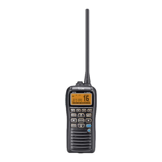
INSTRUCTION MANUAL VHF MARINE TRANSCEIVER iM91D iM92D CLEAR This device complies with Part 15 of the FCC Rules. Operation is subject to the condition that this device does not cause harmful interference. -
Page 2: Foreword
FOREWORD EXPLICIT DEFINITIONS Thank you for purchasing this Icom product. The IC-M91D WORD DEFINITION and IC-M92D are designed and built VHF MARINE TRANSCEIVER Personal death, serious injury or an ex- RDANGER! with Icom’s state of the art technology and craftsmanship. -
Page 3: In Case Of Emergency
IN CASE OF EMERGENCY If your vessel requires assistance, contact other vessels and Or, transmit your Distress call using digital selective calling the Coast Guard by sending a distress call on Channel 16. on Channel 70. USING CHANNEL 16 USING DIGITAL SELECTIVE CALLING (Ch 70) DISTRESS CALL PROCEDURE DISTRESS CALL PROCEDURE... -
Page 4: Recommendation
RECOMMENDATION PRECAUTIONS R WARNING! NEVER CLEAN THE TRANSCEIVER THOROUGHLY WITH FRESH connect the transceiver to an WATER after exposure to saltwater. Otherwise, the trans- AC outlet. This may pose a fi re hazard or result in an electric ceiver's keys, switches and controllers may become inoper- shock. - Page 5 For U.S.A. only: when cleaning, as they will damage the transceiver surfaces. CAUTION: Changes or modifi cations to this transceiver, not expressly approved by Icom Inc., could void your authority to operate this transceiver under FCC regulations.
-
Page 6: Table Of Contents
5 BASIC OPERATION ..........11–16 ■ Channel selection ............11 Icom, Icom Inc. and the Icom logo are registered trademarks of Icom Incor- ■ Call channel programming .........13 porated (Japan) in Japan, the United States, the United Kingdom, Germany, France, Spain, Russia and/or other countries. -
Page 7: Table Of Contents
TABLE OF CONTENTS ■ Adjusting the volume level ..........13 9 OTHER FUNCTIONS ..........71–81 ■ ■ Adjusting the squelch level .........13 MOB (Man OverBoard) ..........71 ■ ■ Receiving and transmitting .........14 Waypoint ..............74 ■ ■ Lock function ..............15 Navigation ..............78 ■ ■... -
Page 8: Operating Rules
OPERATING RULES Priorities (2) OPERATOR’S LICENSE A Restricted Radiotelephone Operator Permit is the license • Read all rules and regulations pertaining to priorities and most often held by small vessel radio operators when a radio keep an up-to-date copy handy. Safety and distress calls is not required for safety purposes. -
Page 9: Supplied Accessories And Attachments
SUPPLIED ACCESSORIES AND ATTACHMENTS ■ Supplied accessories D Handstrap Handstrap Battery pack Battery charger AC adapter (with 2 screws) (Different type may be Pass the handstrap through supplied, depending the loop on the back side of on the version) the transceiver as illustrated at right. -
Page 10: Supplied Accessories And Attachments
SUPPLIED ACCESSORIES AND ATTACHMENTS Battery pack To remove the battery pack: NOTE: When removing or attaching the battery pack, use Turn the screw counter clockwise one quarter turn, then pull a coin or standard screwdriver to loosen or tighten the bot- the battery pack in the direction of the arrow, as shown below. -
Page 11: Panel Description
PANEL DESCRIPTION ■ Front, top, side and rear panels q ANTENNA CONNECTOR Connects to the supplied antenna. w SPEAKER-MICROPHONE CONNECTOR [SP MIC] Connects to the optional external speaker-microphone. NOTE: Attach the [SP MIC] cap when the optional speaker-microphone is not used. Otherwise, water will get into the transceiver. - Page 12 PANEL DESCRIPTION ■ Front, top and rear panels (Continued) i CHANNEL 16 KEY [16/C] ➥ Push to select Channel 16. ( ➥ Hold down for 1 second to select the Call channel. ➥ Hold down for 3 seconds to enter the Call channel programming mode when the Call channel is selected.
-
Page 13: Softkeys
PANEL DESCRIPTION ■ Softkeys The desired functions as described below can be assigned in the Menu screen. Favorite channel [ ] (p. Scan [ ] (p. 17) ➥ Push to set or clear the displayed channel as a Favorite Push to start or stop a Normal or Priority scan. (Tag) channel. -
Page 14: Function Display
PANEL DESCRIPTION ■ ■ Softkeys (Continued) Function display e r t y u i Navigation [ ] (p. 78) After holding down [MOB], or in the MOB or Waypoint list screen, push this key to start navigating to the selected position. - Page 15 PANEL DESCRIPTION t DUPLEX ICON (p. 12) !3 KEY ICON (p. 9) Appears when a duplex channel is selected. Shows the programmed function of the softkeys on the front panel. y FAVORITE CHANNEL ICON (p. 18) !4 TIME ZONE INDICATOR Appears while a Favorite (TAG) channel is selected.
-
Page 16: Softkey Function
PANEL DESCRIPTION ■ ■ Function Display (Continued) Softkey function !5 POSITION INDICATOR ➥ Various functions can be assigned to the softkeys. Shows the current position when valid GPS data is re- When the key function is assigned, the key icon is displayed ceived or the position is manually programmed. -
Page 17: Preparation
PREPARATION ■ MMSI code programming e to enter all 9 digits. The 9 digit MMSI (Maritime Mobile Service Identity: DSC self Repeat step ID) code can be programmed at power ON. After entering the 9 digit code, “FINISH” is automatically selected, and then push [ENTER] to set it. -
Page 18: Basic Operation
BASIC OPERATION ■ Channel selection Call channel IMPORTANT: Prior to using the transceiver for the fi rst Each regular channel group has separate leisure-use call time, the battery pack must be fully charged for optimum channels. The call channel is monitored during Tri-watch. life and operation. - Page 19 BASIC OPERATION Channel group selection Weather channels There are preprogrammed U.S.A. channels, International The transceiver has 10 pre-programmed weather channels. channels and Canadian* channels. These channel groups These are used for monitoring broadcasts from NOAA (Na- may be specifi ed for the operating area. tional Oceanographic and Atmospheric Administration.) The * For only the U.S.A.
-
Page 20: Call Channel Programming
BASIC OPERATION ■ ■ Call channel programming Adjusting the volume level You can program the call channel with your most often-used The volume level can be adjusted with [VOL/SQL] and [∫]/ channels in each channel group for quick recall. [√]/[Ω]/[≈] keys. Select the desired U.S.A., Canada or International chan- q Push... -
Page 21: Receiving And Transmitting
BASIC OPERATION ■ Receiving and transmitting IMPORTANT: To maximize the readability of your transmit- CAUTION: Transmitting without an antenna will damage ted signal, pause a few seconds after pushing [PTT], hold the transceiver. the microphone 5 to 10 cm (2 to 4 inches) from your mouth Hold down [ ] for 1 second to turn power ON. -
Page 22: Lock Function
BASIC OPERATION ■ ■ Lock function AquaQuake water draining function This function electronically locks all keys (except for [PTT], [DISTRESS] and [ ]) to prevent accidental channel changes and function access. The AquaQuake water draining function clears water away ➥ Push [CLEAR/ ] for 1 second to turn the lock function from the speaker grill. -
Page 23: Channel Name Programming
BASIC OPERATION ■ Channel name programming e to input all characters. Repeat step Each channel can be assigned a unique alphanumeric ID of up to 10 characters. Capital letters, 0 to 9, some symbols (! " # $ % & ' ( ) * + , – . / [ \ ] ^ _ : ;... -
Page 24: Scan Operation
SCAN OPERATION ■ Scan types Set the Favorite channels (scanned channels) before scan- Scanning is an effi cient way to locate signals quickly over a ning. Clear the Favorite for unwanted channels which incon- wide frequency range. The transceiver has both priority scan veniently stop scanning, such as those for digital communica- and normal scan. -
Page 25: Setting Favorite (Tag) Channels
SCAN OPERATION ■ ■ Setting Favorite channels Starting a scan For more effi cient scanning, add the desired channels as Fa- First, set the scan type (Priority or Normal scan), WX Alert func- vorite channels, or clear “ for unwanted channels. tion and scan resume timer in the Menu screen. -
Page 26: Dualwatch/Tri-Watch
DUALWATCH/TRI-WATCH ■ ■ Description Operation Dualwatch monitors Channel 16 while you are receiving on Select Dualwatch or Tri-watch in the Menu screen. (p. 84) Y](CH) or [Z](CH) to select the desired operating another channel; Tri-watch monitors Channel 16 and the Push [ call channel while receiving another channel. -
Page 27: Dsc Operation
DSC OPERATION ■ DSC address ID Programming Individual ID A total of 100 DSC address IDs can be programmed and as- After entering the 9 digit code, push [ENTER] to set it. signed a name of up to 10 characters. •... -
Page 28: D Programming Group Id
New2001 DSC OPERATION Programming Group ID Enter “GROUP ID” in the DSC SETTINGS menu. After entering the 9 digit code, push [ENTER] to set it. • The Group ID name programming screen is displayed. ➪ ➪ ❮MENU❯ ❮DSC Settings❯ ❮Group ID❯ (Push [MENU]) (Push [Y]/[Z], then push [ENTER].) Push [ADD]. - Page 29 New2001 DSC OPERATION Deleting Individual/Group ID Enter “INDIVIDUAL ID” or “GROUP ID” in the DSC SET- Push [OK] to delete the ID, and return to the “INDIVIDUAL TINGS menu. ID” or “GROUP ID” list screen. • Push [CANCEL] to cancel it. ➪...
-
Page 30: Position And Time Programming
New2001 DSC OPERATION ■ Position and time programming A Distress call should include the ship’s position and time. If no GPS data is received, your position and UTC (Universal Time Coordinated) time should be manually input. • Manual programming is disabled while GPS data is re- ceived. -
Page 31: Distress Call
New2001 DSC OPERATION ■ Distress call A Distress call should be transmitted if, in the opinion of the NOTE: The distress call is paused for up to 15 seconds Master, the ship or a person is in distress and requires im- when no valid position data is received. -
Page 32: D Regular Call
New2001 DSC OPERATION Regular call The nature of the Distress call should be included in the Dis- While lifting up the key cover on the back side of the trans- tress call. ceiver, hold down [DISTRESS] for 3 seconds to transmit the Distress call. - Page 33 New2001 DSC OPERATION When no GPS data is received or invalid data is received, After transmitting the call, the transceiver waits for an ac- and both position and time have been manually pro- knowledgment call. grammed, the screen as shown below appears. Edit your •...
- Page 34 New2001 DSC OPERATION Distress cancel call While waiting for an acknowledgment call, push [CAN- The Distress cancel call is transmitted. CEL]. Channel 16 is automatically selected. Push [CONTINUE]. • Report your situation using the microphone. • After the report, push [EXIT] to return to the normal operating •...
-
Page 35: Transmitting Dsc Calls
New2001 DSC OPERATION ■ About Manual Inputting: Transmitting DSC calls Enter a desired individual ID in the following way: • Select a desired number using [Y]/[Z]/[Ω]/[≈]. To ensure correct operation of the DSC function, make • Push [ENTER] to set it. sure you correctly set the CH70 SQL LEVEL. - Page 36 New2001 DSC OPERATION Transmitting an Individual call (continued) Y](CH)/[Z](CH), Select a desired intership channel using [ Standby on Channel 70 until an acknowledgement is re- then push [ENTER]. ceived. • Intership channels are already preset into the transceiver in the recommended order.
- Page 37 New2001 DSC OPERATION Transmitting an Individual Acknowledgement Or, when the acknowledgement ‘Unable to comply’ is re- When receiving an Individual call, you can transmit an ac- ceived, beeps sound and the screen below is displayed. knowledgement (‘Able to Comply,’ ‘Propose New Channel’ or ‘Unable to Comply’) by using the on-screen prompts (Quick ACK.) Also, you can send an acknowledgement through the MENU system (Man ual ACK.)
- Page 38 New2001 DSC OPERATION Transmitting an Individual Acknowledgement (continued) Select one of three options, then push [ENTER]. The Individual ACK confi rmation screen is displayed. Push [CALL] to transmit an acknowledgement call. • Able to Comply : Make an acknowledgment call without any changes.
- Page 39 New2001 DSC OPERATION Transmitting a Group call Manual ACK: The Group call function allows you to transmit a DSC signal Enter “INDIVIDUAL ACK” in the DSC CALLS menu. to only a specifi c group. ➪ ➪ ❮MENU❯ ❮DSC Calls❯ ❮Individual ACK❯ Enter “GROUP CALL”...
- Page 40 New2001 DSC OPERATION Transmitting a Group call (continued) About Manual Inputting: Push [CALL] to transmit the Group call. • If Channel 70 is busy, the transceiver stands by until the channel Enter a desired group ID in the following way: becomes clear.
- Page 41 New2001 DSC OPERATION Transmitting an All Ships call All ships, that have DSC transceiver, use Channel 70 as their A confi rmation screen appears. ‘listening channel.’ When you want to announce a message to • Confi rm the call contents. these ships within range, use the ‘All Ships Call’...
-
Page 42: D Transmitting A Position Request Call
New2001 DSC OPERATION Transmitting a Position Request Call Transmit a Position Request Call when you want to know a About Manual Inputting: specifi c ship’s current position, etc. Enter a desired individual ID in the following way: • Select a desired number using [Ω]/[≈]. •... - Page 43 New2001 DSC OPERATION When the acknowledgement call is received, beeps sound Push [CALL] to transmit the Position Request Call. and the following screen is displayed. • If Channel 70 is busy, the transceiver stands by until the channel becomes clear. After the Position Request Call has been transmitted, the Push [ALARM OFF] to stop the beeps, and then the screen following screen is displayed.
- Page 44 New2001 DSC OPERATION Transmitting a Position Report Call Transmit a Position Report Call when you want to announce About Manual Inputting: your own position to a specifi c ship. Enter a desired individual ID in the following way: • Select a desired number using [Ω]/[≈]. •...
- Page 45 New2001 DSC OPERATION Push [CALL] to transmit the Position Report Call. When no GPS data is received or invalid data is received, • If Channel 70 is busy, the transceiver stands by until the channel and both position and time have been manually programmed, becomes clear.
- Page 46 New2001 DSC OPERATION Transmitting a Polling Request Call Transmit a Polling Request Call when you want to know a About Manual Inputting: specifi c vessel is in the communication area, or not. Enter a desired individual ID in the following way: •...
- Page 47 New2001 DSC OPERATION When the acknowledgement call is received, beeps sound Push [CALL] to transmit the Polling Request Call. and the following screen is displayed. • If Channel 70 is busy, the transceiver stands by until the channel becomes clear. Push [ALARM OFF] to stop the beeps, and then the screen After the Polling Request Call has been transmitted, the as shown below is displayed.
-
Page 48: D Transmitting A Test Call
New2001 DSC OPERATION Transmitting a Test call Testing on the exclusive DSC distress and safety calling chan- About Manual Inputting: nels should be avoided as much as possible. When testing on Enter a desired address ID in the following way: a distress/safety channel is unavoidable, you should indicate •... - Page 49 New2001 DSC OPERATION When the acknowledgement call is received, beeps sound Push [CALL] to transmit the Test call. • If Channel 70 is busy, the transceiver stands by until the channel and the following screen is displayed. becomes clear. After the Test call has been transmitted, the following Push [ALARM OFF] to stop the beeps, and then the screen screen is displayed.
- Page 50 New2001 DSC OPERATION Transmitting a Test Acknowledgement call When the “TEST ACK” in DSC settings is set to ‘Auto TX’ The Test ACK confi rmation screen is displayed. 66), the transceiver automatically transmits a reply call Push [CALL] to transmit the acknowledgement call. when receiving a Test call.
- Page 51 New2001 DSC OPERATION Manual ACK: Enter “TEST ACK” in the DSC CALLS menu. The Test ACK confi rmation screen is displayed. Push [CALL] to transmit the acknowledgement call. ➪ ➪ ❮MENU❯ ❮DSC Calls❯ ❮Test ACK❯ (Push [MENU]) (Push [Y]/[Z], then push [ENTER].) •...
- Page 52 New2001 DSC OPERATION Transmitting a Position Reply call • Push [INFO] to display the Position Request call information. Transmit a Position Reply call when a Position Request call Push [BACK] to return to the previous screen, or push [ACK]. is received. When the “POSITION ACK”...
- Page 53 New2001 DSC OPERATION Manual Reply: While transmitting the reply call, the screen shown below Enter “POSITION REPLY” in the DSC CALLS menu. is displayed, and then returns to the normal operating mode. ➪ ➪ ❮MENU❯ ❮DSC Calls❯ ❮Position Reply❯ (Push [MENU]) (Push [Y]/[Z], then push [ENTER].) •...
- Page 54 New2001 DSC OPERATION Transmitting a Position Report Reply call • Push [INFO] to display the Position Report Request call informa- Transmit a Position Report Reply call when a Position Report tion. Request call is received. Push [BACK] to return to the previous screen, or push [ACK]. Quick Reply: When a Position Report Request call is received, beeps sound and the screen as shown below is displayed.
- Page 55 New2001 DSC OPERATION Manual Reply: Enter “POSITION REPORT REPLY” in the DSC CALLS The Position Report Reply call confi rmation screen is dis- menu. played. Push [CALL] to transmit the acknowledgement call. ➪ ➪ ❮MENU❯ ❮DSC Calls❯ ❮Position Report Reply❯ (Push [MENU]) (Push [Y]/[Z], then push [ENTER].) •...
- Page 56 New2001 DSC OPERATION Transmitting a Polling Reply call • Push [INFO] to display the Polling Request call information. Transmit a Polling Reply call when a Polling Request call is Push [BACK] to return to the previous screen, or push [ACK]. received.
- Page 57 New2001 DSC OPERATION Manual Reply: Enter “POLLING REPLY” in the DSC CALLS menu. While transmitting the reply call, the screen shown below is displayed, and then returns to the normal operating ➪ ➪ ❮MENU❯ ❮DSC Calls❯ ❮Polling Reply❯ mode. (Push [MENU]) (Push [Y]/[Z], then push [ENTER].) •...
-
Page 58: Receiving Dsc Calls
New2001 DSC OPERATION ■ Receiving DSC calls [INFO] ➥ Push to display the Received call information. Receiving a Distress Call (p. 63) When a Distress Call is received: ➥ The emergency alarm sounds for 2 minutes. ➥ “RCVD DISTRESS” pops up and the LCD backlight blinks. - Page 59 New2001 DSC OPERATION Receiving a Distress Acknowledgement When a Distress Acknowledgement sent to another ship is [INFO] ➥ Push to display the Received call received: information. (p. 63) ➥ The emergency alarm sounds for 2 minutes. ➥ “RCVD DISTRESS ACK” pops up and the LCD backlight blinks.
- Page 60 New2001 DSC OPERATION Receiving a Distress Relay Call When a Distress Relay call is received: [INFO] ➥ The emergency alarm sounds for 2 minutes. ➥ Push to display the Received call information. (p. 63) ➥ “RCVD DISTRESS RELAY” pops up and the LCD back- light blinks.
- Page 61 New2001 DSC OPERATION Receiving a Distress Relay Acknowledgement When a Distress Relay Acknowledgement is received: [INFO] ➥ The emergency alarm sounds for 2 minutes. ➥ Push to display the Received call information. (p. 63) ➥ “RCVD DIST RELAY ACK” pops up and the LCD backlight blinks.
- Page 62 New2001 DSC OPERATION Receiving an Individual Call When an Individual Call is received: [IGN] ➥ The alarm sounds for 2 minutes. ➥ Push to ignore the Call and return to the normal operating ➥ “RCVD INDIVIDUAL CALL” pops up. The LCD backlight mode.
- Page 63 New2001 DSC OPERATION Receiving a Group Call When a Group Call is received: [IGN] ➥ The alarm sounds for 2 minutes. ➥ Push to ignore the Call and return to the normal operat- ➥ “RCVD GROUP CALL” pops up. The LCD backlight may ing mode.
- Page 64 New2001 DSC OPERATION Receiving an All Ships Call When an All Ships Call is received: [IGN] ➥ The alarm sounds for 2 minutes. ➥ Push to ignore the Call and return to the normal operat- ➥ “RCVD ALL SHIPS CALL” pops up. The LCD backlight may ing mode.
- Page 65 New2001 DSC OPERATION Receiving a Geographical Area Call When a Geographical Area Call (for the area you are in) is [IGN] ➥ Push to ignore the Call and return to the normal operat- received: ➥ The alarm sounds for 2 minutes. ing mode.
- Page 66 New2001 DSC OPERATION Receiving a Position Request Call When a Position Request Call is received: [IGN] ➥ The alarm sounds for 2 minutes. ➥ Push to ignore the Call and return to the normal operat- ➥ “RCVD POS REQUEST” pops up. The LCD backlight ing mode.
- Page 67 New2001 DSC OPERATION Receiving a Position Report Call When a Position Report Call is received: [EXIT] ➥ The alarm sounds for 2 minutes. ➥ Push to ignore the Call and return to the normal operat- ➥ “RCVD POSITION REPORT” pops up. The LCD backlight ing mode.
-
Page 68: D Receiving A Polling Request Call
New2001 DSC OPERATION D Receiving a Polling Request call When a Polling Request call is received: [IGN] ➥ The alarm sounds for 2 minutes. ➥ Push to ignore the Call and return to the normal operat- ➥ “RCVD POLLING REQUEST” pops up. The LCD backlight ing mode. - Page 69 New2001 DSC OPERATION D Receiving a Test Call [IGN] When a Test Call is received: ➥ Push to ignore the Call and return to the normal operat- ➥ The alarm sounds for 2 minutes. ➥ “RCVD TEST CALL” pops up. The LCD backlight blinks for ing mode.
-
Page 70: Received Call Log
New2001 DSC OPERATION ■ Receiving a Test Acknowledgement Call Received Call log When a Test Acknowledgement Call is received: ➥ The alarm sounds for 2 minutes. The transceiver automatically stores up to 50 distress mes- ➥ “RCVD TEST ACK” pops up. The LCD backlight blinks for sages and 50 other messages, and they can be used as a 2 minutes. - Page 71 New2001 DSC OPERATION ] or [] to select the desired item, then push [EN- Push [ Other messages TER]. Push [LOG] to enter “RCVD CALL LOG” in the DSC CALLS • The message in the unopened fi le has not been read. menu, or you can enter it through the Menu screen.
-
Page 72: Transmitted Call Log
New2001 DSC OPERATION ■ Other messages (Continued) Transmitted Call log ] or [] to scroll the message contents. Push [ • The stored message has various information, depending on the The transceiver automatically stores up to 50 transmitted DSC call type. calls, and the logs can be used as a supplement to your log- •... -
Page 73: Dsc Settings
New2001 DSC OPERATION ■ DSC Settings D Position Input ] or [] to select “Auto TX” or “Manual TX,” then Push [ (See page 23) D Add Individual ID/Group ID push [ENTER]. (See pages 20 and 21) D Delete Individual ID/Group ID •... -
Page 74: Channel 16 Switch Function
New2001 DSC OPERATION D Channel 16 Switch function By regulation, after receiving a Distress call, the transceiv- Auto (No Delay) : After receiving a Distress call, and er switches the operating channel to Channel 16. However, [ACPT] is pushed on the confirmation when this setting is set to “OFF,”... -
Page 75: Channel 70 Squelch Level
New2001 DSC OPERATION D Alarm D Channel 70 Squelch level Set the Alarm function ON or OFF, depending on the Cat- Set the squelch level on Channel 70. egory or Status. The transceiver has 11 squelch levels between 1 (loose squelch) and 10 (tight squelch) and OPEN. - Page 76 New2001 DSC OPERATION D DSC Loop Test D Channel 70 Watch function The DSC loop test function sends transmit DSC signals to Select whether or not the transceiver monitors Channel 70. the receive AF circuit to compare and check the TX and RX q Enter “CH 70 Watch”...
-
Page 77: Dsc Operation
New2001 DSC OPERATION Standby : While receiving no signal, the transceiver moni- tors Channel 70 according to the Scan Speed time cycle. Busy : While receiving no signal on the operating chan- nel, the transceiver monitors Channel 70 ac- cording to the Scan Speed time cycle. While receiving a signal on the operating chan- nel, the transceiver monitors Channel 70 every 1.5 seconds. -
Page 78: Other Functions
OTHER FUNCTIONS ■ MOB (Man OverBoard) The transceiver can register an MOB (Man OverBoard*) point After the information screen appears, push [ENTER] to with its position data. open the MOB screen, then the navigation to the stored * The situation in which a person has fallen into the water and is in point will start. - Page 79 OTHER FUNCTIONS Starting Navigation to the MOB point: Push [NAV] To check the stored MOB point: The transceiver can navigate to the MOB point. Push [MENU] to enter the MENU screen. ➥ Push [NAV] to start navigation to the MOB point. Push []/[] and select “MOB”...
- Page 80 OTHER FUNCTIONS ■ MOB (Man Overboard) (Continued) Deleting an MOB point: Push [DEL] Editing the MOB point: Push [EDIT] The stored the MOB point can be deleted. The stored MOB position can be changed. Please note that a deleted MOB point cannot be restored. Push [EDIT] to enter the position data editing screen.
-
Page 81: Waypoint
OTHER FUNCTIONS ■ Waypoint You can store your vessel’s position information wherever you To store a received position: are, and also the position information of the vessel you re- After receiving a DSC call that includes the position informa- ceived a DSC call from, as a waypoint. The transceiver can tion, the position can be registered as a waypoint. - Page 82 OTHER FUNCTIONS ■ Waypoint (Continued) To check the stored waypoint: Sorting the waypoints: Push [SORT] The transceiver can sort the waypoints on the waypoint list Push [MENU] to enter the MENU screen. screen. Push []/[] to select “Waypoint” to enter the waypoint ➥...
- Page 83 OTHER FUNCTIONS Adding the waypoint: Push [ADD] After entering the name, select “FINISH” by pushing [ New waypoints can be manually programmed with a name [Z]/[Ω]/[≈], then push [ENTER] to set it and enter the posi- and position data. tion data editing screen. Push [ADD] to enter the name programming screen.
- Page 84 OTHER FUNCTIONS ■ Waypoint (Continued) Editing the waypoint: Push [EDIT] The stored waypoint name and its position data can be After the confi rmation screen appears, push [OK] to save changed. the waypoint and return to the waypoint list screen. Push [EDIT] to enter the name programming screen.
-
Page 85: Navigation
OTHER FUNCTIONS ■ Navigation The Navigation function navigates from your current position Starting Navigation to the waypoint: to the specifi ed waypoint (including MOB point). Push [MENU] to enter the MENU screen. The MOB point or waypoint has already been registered. Push []/[] to select “Waypoint”... - Page 86 OTHER FUNCTIONS ■ Navigation (Continued) Navigation screen description: • Push [RNG] to open the range setting window, then push Distance Destination Compass direction [∫]/[√]/[Ω]/[≈] to select the desired range. Eight ranges are selectable. The range shows the radius of a compass circle. Waypoint SOG (Speed Over Ground) COG (Course Over Ground)
-
Page 87: Compass Screen
OTHER FUNCTIONS ■ ■ Compass screen GPS status screen The compass screen displays your vessel’s COG (Course GPS Status displays the quantity, signal power and position Over Ground) and SOG (Speed Over Ground) which can be of the GPS satellites. checked at a glance. -
Page 88: Gps Status Screen
OTHER FUNCTIONS ■ GPS status screen (Continued) • About the sky view • Satellite signal power screen description ●: Tracking satellite. Satellite A ○: Untracking satellite Satellite Satellite Elevation angle 0 degree line number signal Elevation angle 30 degree line power Elevation angle 60 degree line Elevation angle 90 degree line... -
Page 89: Menu Screen Operation
MENU SCREEN OPERATION ■ Menu screen operation Entering the Menu screen and operation The Menu screen is used for programming infrequently changed values, function settings or sending DSC calls. In addition to this page, see pages 84 through 88 for details. -
Page 90: Menu Screen Items
MENU SCREEN OPERATION ■ Menu screen items Confi guration The Menu screen contains the following items. DSC Calls Item Ref. Item Ref. Item Ref. Item Ref. • Backlight • Noise Cancel • Individual Call • Transmitted Call Log • Display Contrast •... -
Page 91: Radio Settings Items
MENU SCREEN OPERATION ■ Radio Settings items Scan type Dual/Tri-watch The transceiver has two scan types; Normal scan and Prior- This item can be selected as Dualwatch or Tri-watch. (p. 19) ity scan. A Normal scan searches all Favorite channels in the (Default: Dualwatch) selected channel group. -
Page 92: Confi Guration Items
MENU SCREEN OPERATION ■ ■ Radio settings items (Continued) Confi guration items WX Alert Backlight A NOAA broadcast station transmits a weather alert tone be- fore important weather information. The function display and keys can be backlit for better visibil- “WX ”... -
Page 93: Key Assignment
MENU SCREEN OPERATION Key Assignment UTC Offset Desired functions can be assigned to the softkeys. Set the offset time between the UTC (Universal Time Coordi- When the “KEY ASSIGNMENT” screen is displayed, push nated) and your local time to between –14:00 and +14:00 (in [∫]/[√] to select the desired softkey, and then push [EN- 1 minute steps). -
Page 94: Inactivity Timer
MENU SCREEN OPERATION ■ Confi guration items (Continued) Inactivity Timer • RX Set the inactivity timer to between 1 and 10 minutes (in 1 minute Turn the receive Noise Cancel function ON or OFF. steps) or OFF for the “Not DSC Related” items, and to between (Default: OFF) 1 and 15 minutes or OFF for the “DSC Related”... -
Page 95: Float 'N Flash
MENU SCREEN OPERATION • DSC Related Float ’n Flash When the LCD displays the screen related to the DSC, and no Float ’n Flash function detects that the transceiver has come key operation occurs for this set period except during distress in contact with water. -
Page 96: Battery Charging
fi re. R DANGER! Use the battery only with the transceiver for which it is R DANGER! Use and charge only specifi ed Icom battery pack with specifi ed. Never use a battery with any other equipment, or for any Icom radios or Icom chargers. -
Page 97: D Charging Caution
D Charging caution temperature range: ±0˚C to +45˚C (+32˚F to +113˚F). Icom recom- Charge the battery pack at least once every six months, even if it mends charging the battery at +20˚C (+68˚F). The battery may heat has been not used for a long period of time. The battery pack will up or rupture if charged out of the specifi... -
Page 98: Regular Battery Charger
BATTERY CHARGING ■ Regular battery charger Regular charging with the BC-204 + BC-147S BC-204 installation • To a desktop The BC-204 with BC-147S provides regular charging of the • To a wall Li-ion battery pack. Supplied screws • Charging time: approximately 13 hours. Supplied screws Transceiver Battery... -
Page 99: Optional Battery Chargers
BATTERY CHARGING ■ Optional battery chargers Rapid charging with the BC-197 + BC-157S Rapid charging with the BC-205 + BC-123S or OPC-656 The optional BC-205 with the BC-123S will provide rapid charging of the Li-ion battery pack. (Charging time: approxi- The optional BC-197 with the BC-157S will simultaneously mately 4 hours) charge up to 6 Li-ion battery packs. - Page 100 BATTERY CHARGING IMPORTANT: Battery charging caution Ensure the guide tabs on the battery pack are correctly aligned with the guide rails inside the charger adapter. (This is an illustration of the BC-204.) Tabs Guide rail...
-
Page 101: Optional Speaker-Microphone
OPTIONAL SPEAKER-MICROPHONE ■ ■ HM-167 descriptions Attachment Turn power OFF before attaching the speaker-microphone. Alligator type clip Then, insert the speaker-microphone’s connector into the To attach the speaker-microphone [SP MIC] connector and carefully screw it tight, as shown in to your shirt or collar, etc. the diagram below. -
Page 102: Troubleshooting
TROUBLESHOOTING PROBLEM POSSIBLE CAUSE SOLUTION REF. The transceiver does • The Battery is exhausted or over dis- • Recharge the battery pack. p. 89 not turn ON. charged. • The Battery pack is not correctly attached. • Correctly attach the battery pack. p. -
Page 103: Specifications And Options
SPECIFICATIONS AND OPTIONS ■ Specifi cations • Modulation system : Variable reactance frequency modulation General • Max. frequency deviation : ±5.0 kHz • Frequency coverage • Adjacent channel power : 70 dB Tx 156.025–157.425 MHz • Spurious emissions (typical) Rx 156.050–163.275 MHz (USA and EXP versions) USA and EXP versions : –68 dBc Rx 156.300–162.025 MHz (AUS version) -
Page 104: Options
Icom transceiver. Icom is not responsible instead of the AC adapter. for the destruction or damage to an Icom transceiver in the event (OPC-515L for BC-204 and BC-205 : OPC-656 for BC-197) the Icom transceiver is used with equipment that is not manufac-... -
Page 105: Vhf Marine Channel List
VHF MARINE CHANNEL LIST Channel number Frequency (MHz) Channel number Frequency (MHz) Channel number Frequency (MHz) Channel number Frequency (MHz) CAN Transmit Receive CAN Transmit Receive CAN Transmit Receive CAN Transmit Receive 156.050 160.650 157.050 161.650 156.425 156.425 157.325 157.325 156.050 156.050 21A 157.050 157.050 156.475 156.475... -
Page 106: Safety Training Information
• ALWAYS keep the antenna at least 2.5 cm (1 inch) away from the body Electromagnetic Fields. when transmitting and only use the Icom belt clip which is listed on page 97 when attaching the radio to your belt, etc., to ensure FCC RF •... -
Page 107: Safety Training Information
Interférence électromagnétique et compatibilité FCC en matière d'exposition aux RF sans fi l; attache pour ceinture (MB- En mode de transmission, votre radio Icom produit de l'énergie de RF qui 109), bloc-piles rechargeable au lithium-ion (BP-275). peut provoquer des interférences avec d'autres appareils ou systèmes. Pour CAUTION éviter de telles interférences, mettez la radio hors tension dans les secteurs... - Page 108 A-7023D-1EX Printed in Japan © 2012 Icom Inc. 1-1-32 Kamiminami, Hirano-ku, Osaka 547-0003, Japan Printed on recycled paper with soy ink.