Table of Contents
Advertisement
Available languages
Available languages
Operator: Save these instructions for future use!
FAILURE TO READ AND FOLLOW ALL INSTRUCTIONS CAREFULLY
BEFORE INSTALLING OR OPERATING THIS CONTROL COULD CAUSE
PERSONAL INJURY AND/OR PROPERTY DAMAGE.
Your new White-Rodgers Digital Thermostat uses the technol-
ogy of a solid-state microcomputer to provide precise tempera-
ture control.
Features:
• Simultaneous heat and cool setpoint storage
• Pre-set temperature control
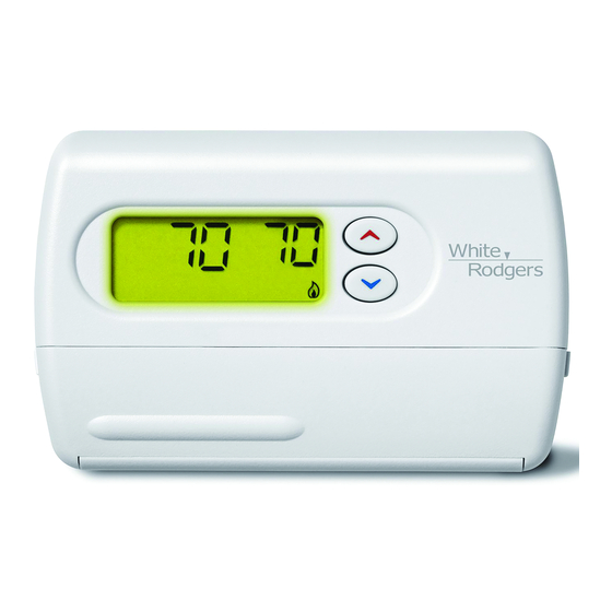
• Backlit display
• LCD continuously displays setpoint and room temperature
This thermostat is intended for use with a low voltage system;
do not use this thermostat with a line voltage system. If in doubt
about whether your wiring is millivolt, line, or low voltage, have
it inspected by a qualified heating and air conditioning contrac-
tor or electrician.
Do not exceed the specification ratings.
All wiring must conform to local and national electrical codes
and ordinances.
This control is a precision instrument, and should be handled
carefully. Rough handling or distorting components could
cause the control to malfunction.
CAUTION
!
To prevent electrical shock and/or equipment damage,
disconnect electric power to system at main fuse or
circuit breaker box until installation is complete.
ELECTRICAL DATA
Electrical Rating:
8 to 30 VAC 50/60 Hz. or D.C.
0.05 to 1.0 Amps (Load per terminal)
1.5 Amps Maximum Total Load (All terminals combined)
THERMAL DATA
Setpoint Temperature Range:
45°F to 90°F (7°C to 32°C)
Operating Ambient Temperature Range:
32°F to 105°F
Operating Humidity Range:
0 to 90% RH (non-condensing)
Shipping Temperature Range:
-4°F to 150°F
Non-Programmable Electronic Digital Thermostat
• °F/°C convertibility
• Temperature range 45° to 90°F
• RC, RH, C, W, Y, G , O and B terminals
• Optional C terminal (Dual Power option)
• B and O terminals for single stage heat pumps (no auxiliary
heat) or damper operation
• Setpoint storage in case of power loss
• 2 "AA" alkaline batteries included
Do not use on circuits exceeding specified voltage.
Higher voltage will damage control and could cause
shock or fire hazard.
Do not short out terminals on gas valve or primary
control to test. Short or incorrect wiring will damage
thermostat and could cause personal injury and/or
property damage.
Thermostat installation and all components of the sys-
tem shall conform to Class II circuits per the NEC code.
APPLICATIONS
For use with:
•
Standard heat/cool or heat only systems
•
Electric heat systems
•
Gas or oil fired systems
•
Gas systems with intermittent ignition devices (I.I.D.)
and/or vent dampers
•
Hydronic (hot water or steam) systems
•
Single-stage heat pump systems (no auxiliary heat)
•
Millivolt systems
DO NOT USE WITH:
•
Multi-stage systems
•
Systems exceeding 30 VAC and 1.5 amps
•
3-wire zoned hydronic heating systems
White-Rodgers is a division
of Emerson Electric Co.
www.white-rodgers.com
1F86-344
INSTALLATION AND
OPERATION INSTRUCTIONS
DESCRIPTION
PRECAUTIONS
WARNING
!
SPECIFICATIONS
PART NO. 37-6585B
Replaces 37-6585A
0745
Advertisement
Table of Contents

Related Manuals for White Rodgers 1F86-344


Summary of Contents for White Rodgers 1F86-344
-
Page 1: Specifications
1F86-344 Non-Programmable Electronic Digital Thermostat INSTALLATION AND OPERATION INSTRUCTIONS Operator: Save these instructions for future use! FAILURE TO READ AND FOLLOW ALL INSTRUCTIONS CAREFULLY BEFORE INSTALLING OR OPERATING THIS CONTROL COULD CAUSE PERSONAL INJURY AND/OR PROPERTY DAMAGE. DESCRIPTION Your new White-Rodgers Digital Thermostat uses the technol- •... -
Page 2: Installation
INSTALLATION REMOVE OLD THERMOSTAT Screw anchors 1. Shut off electricity at the main fuse box until installation is complete. Ensure that electrical power is disconnected. 2. Remove the front cover of the old thermostat. With wires still attached, remove wall plate from the wall. If the old thermostat has a wall mounting plate, remove the thermostat and the wall mounting plate as an assembly. -
Page 3: Wiring Diagrams
JUMPER THERMOSTAT WIRE C ‡ THERMOSTAT SYSTEM C ‡ SYSTEM Cooling Heating 24 VAC 120 VAC System Relay System Heating Neutral Relay System HEATING TRANSFORMER 24 VAC 120 VAC NOTE Neutral For 2-wire Heat only, attach to RH and W TRANSFORMER 24 VAC 120 VAC... -
Page 4: The Thermostat Buttons And Switches
Before you begin using your thermostat, you should be familiar with its features and with the display and the location and operation of the thermostat buttons. Your thermostat consists of two parts: the thermostat cover and the base. To remove the cover, pull it straight out from the base. -
Page 5: Setting The Thermostat
2) Select FA or SL (Fast or Slow) Heating Cycle Rate - The SETTING THE THERMOSTAT FA setting is frequently used for gas, oil or electric heat. The This thermostat is very easy to operate. Set the SYSTEM switch SL setting produces a longer heating cycle which is nor- to either HEAT or COOL then press until the mally for hot water or steam (hydronic) systems. - Page 6 HOMEOWNER HELP LINE: 1-800-284-2925 The Emerson logo is a St. Louis, Missouri Markham, Ontario trademark and service mark www.white-rodgers.com of Emerson Electric Co.
-
Page 7: Especificaciones
1F86-344 Termostato digital electrónico no programable INSTRUCCIONES DE INSTALACIÓN Y OPERACIÓN Sr. operador: ¡Conserve estas instrucciones para consultarlas en cualquier momento! EL NO LEER Y SEGUIR CON CUIDADO TODAS LAS INSTRUCCIONES ANTES DE INSTALAR O UTILIZAR ESTE CONTROL PODRÍA CAUSAR LESIONES PERSONALES Y/O DAÑOS MATERIALES. -
Page 8: Instalación
INSTALACIÓN Anclajes Tarugos plásticos RETIRE EL TERMOSTATO VIEJO 1. Apague la electricidad en la caja de fusibles principal hasta que haya finalizado la instalación. Asegúrese de que la alimentación eléctrica esté desconectada. 2. Retire la cubierta delantera del termostato viejo. Con los cables aún conectados, retire la placa de la pared. Si el termostato viejo tiene una placa de montaje sobre pared, retire el termostato y la placa juntos. - Page 9 SISTEMA C ‡ CABLE DE PUENTE TERMOSTATO SISTEMA C ‡ Vivo Sistema Relé Sistema TERMOSTATO 24 VAC 120 VAC refrigeración ventilador calefacción Neutro Relé Sistema TRANSFORMADOR ventilador calefacción Vivo DE CALEFACCIÓN NOTA 24 VAC 120 VAC Vivo Neutro Para sólo calor con 2 cables, 24 VAC 120 VCA conectar a RH y W...
-
Page 10: Operación
OPERACIÓN Antes de que comience a usar su termostato, debe familiarizarse con sus funciones y con la pantalla y la ubicación y funcionamiento de los diferentes botones. Su termostato consta de dos partes: la cubierta del termostato y la base. Para retirar la cubierta, tire suavemente de ella para separarla de la base. Para volver a colocarla, alinee la cubierta con la base y presione suavemente hasta que se enganche en la base. Los botones e interruptores del termostato (vea la figura 8) Sube el ajuste de temperatura. - Page 11 2) Seleccione Display Backlight (luz de fondo de pantalla) (d-L OFF [desactivada] u ON [activada]) - La luz de fondo mejora el contraste de la pantalla en condiciones de poca luz. Si selecciona backlight ON, la luz se mantendrá encendida durante un breve tiempo después de presionar cualquier botón.
- Page 12 LÍNEA DE AYUDA PARA EL USUARIO: 1-800-284-2925 El logotipo de Emerson St. Louis, Missouri Markham, Ontario es una marca comercial y una marca de servicio www.white-rodgers.com de Emerson Electric Co.