Table of Contents
Advertisement
Quick Links
Save these instructions for future use!
FAILURE TO READ AND FOLLOW ALL INSTRUCTIONS
CAREFULLY BEFORE INSTALLING OR OPERATING THIS
CONTROL COULD CAUSE PERSONAL INJURY AND/OR
PROPERTY DAMAGE.
APPLICATIONS
YOUR THERMOSTAT REPLACES
Description
Heat Pump (No Aux. or Emergency Heat)
Heat Pump (with 1 Aux. or Emergency Heat Stage)
Standard Heat & Cooling Systems
Two Stage Heat & Two Stage Cool
Standard Heat Only Systems
Millivolt Heat Only Systems - Floor or Wall Furnaces
Standard Central Air Conditioning
Gas or Oil Heat
Electric Furnace
Hydronic (Hot Water) Zone Heat – 2 Wires
Hydronic (Hot Water) Zone Heat – 3 Wires
SPECIFICATIONS
Electrical Rating:
Battery Power ................................................. mV to 30 VAC, 50/60 Hz or DC
Input-Hardwire ................................................ 20 to 30 VAC
Terminal Load ........................................................ 1.5 A per terminal, 2.5A maximum all terminals combined
Setpoint Range ...................................................... 45° to 90°F (7° to 32°C)
Differential (Single Stage) ...................................... Heat 0.8°F; Cool 1.2°F (adjustable)
Differential (Heat Pump) ........................................ Heat 1.2°F; Cool 1.2°F (adjustable)
Operating Ambient ................................................. 32° to +105°F (0° to +41°C)
Operating Humidity ................................................ 90% non-condensing max.
Shipping Temperature Range ................................ -40° to +150°F (-40° to +65°C)
Dimensions Thermostat ......................................... 3-3/4"H x 4-3/4"W x 1-1/2"D
PRECAUTIONS
WARNING
!
Do not use on circuits exceeding specifi ed voltage.
Higher voltage will damage control and could cause
shock or fi re hazard.
Thermostat installation and all components of the
system shall conform to Class II (current limited)
circuits per the NEC code. Failure to do so could cause
a fi re hazard.
CAUTION
!
To prevent electrical shock and/or equipment damage,
disconnect electric power to system at main fuse or
circuit breaker box until installation is complete.
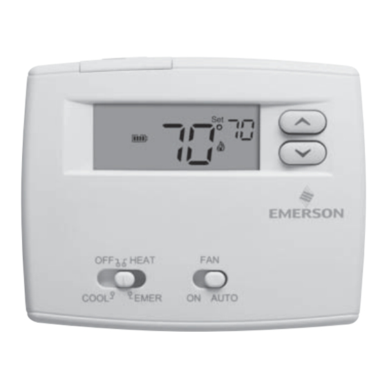
Blue 2" Heat Pump Thermostat
Installation and Operating Instructions
Model
1F89-0211
Yes
Yes
Yes
No
Yes
Yes
Yes
Yes
Yes
Yes
No
Index
Installation
Wiring Diagrams
Thermostat Quick Reference
Installer Confi guration Menu
Operation
Troubleshooting
www.white-rodgers.com
1
Heat Pump or Single Stage
Programming Choices
Non-Programmable
1F89-0211 Thermostat
PART NO. 37-6997C
Replaces 37-6997B
Page
2
3
4
4
6
7
0932
Advertisement
Table of Contents

Related Manuals for White Rodgers BLUE 2 1F89-0211


Summary of Contents for White Rodgers BLUE 2 1F89-0211
-
Page 1: Specifications
Save these instructions for future use! FAILURE TO READ AND FOLLOW ALL INSTRUCTIONS CAREFULLY BEFORE INSTALLING OR OPERATING THIS CONTROL COULD CAUSE PERSONAL INJURY AND/OR PROPERTY DAMAGE. APPLICATIONS YOUR THERMOSTAT REPLACES Description Heat Pump (No Aux. or Emergency Heat) Heat Pump (with 1 Aux. or Emergency Heat Stage) Standard Heat &... -
Page 2: Battery Location
INSTALLATION REMOVE OLD THERMOSTAT 1. Shut off electricity at the main fuse box until installation is complete. Ensure that electrical power is disconnected. 2. Remove the front cover of the old thermostat. With wires still attached, remove wall plate from the wall. If the old thermostat has a wall mounting plate, remove the thermostat and the wall mounting plate as an assembly. -
Page 3: Wiring Diagrams
WIRING DIAGRAMS Changeover Relay* Compressor Contactor * Changeover Relay is energized in COOL when O/B switch is in the “O” position Changeover Relay is energized in HEAT when O/B switch is in the “B” position Figure 2. Typical wiring diagram for single transformer systems NOTE If safety circuits are in only one of the systems,... -
Page 4: Thermostat Quick Reference
THERMOSTAT QUICK REFERENCE Before you begin programming your thermostat, you should be familiar with its features and with the display and the location and operation of the thermostat buttons and switches (see fi g. 5). Your thermostat consists of two parts: the thermostat cover and the base. - Page 5 INSTALLER/CONFIGURATION MENU Menu Press Reference Number 4) Select Compressor Lockout CL OFF or ON - Selecting CL On will cause the thermostat to wait 5 minutes between cooling cycles. This is intended to help protect the compressor from short cycling. Some newer compressors already have a time delay built in and do not require this feature.
-
Page 6: Check Thermostat Operation
OPERATION CHECK THERMOSTAT OPERATION If at any time during testing your system does not operate properly, contact a qualifi ed service person. Turn on power to the system. Fan Operation If your system does not have a G terminal connection, skip to Heating System. -
Page 7: Troubleshooting
TROUBLESHOOTING Reset Operation If a voltage spike or static discharge blanks out the display or causes erratic thermostat operation, you may need to reset the thermostat. To reset, the System Switch must be in Cool, HEAT, or EMER. Simultaneously hold the Symptom Possible Cause No Heat/No Cool/No Fan... - Page 8 TROUBLESHOOTING STAGING Second Stage - Auxiliary Heat Most heat pump systems have an Auxiliary or Second Stage electric heater or gas furnace. Heat produced by a heat pump is economical but may not always have the capacity to maintain a comfortable room temperature setting. Auxiliary/Second Stage heat is usually less economical but the added heat capacity assures the system can provide enough heat to satisfy the thermostat setting.
- Page 9 1-800-284-2925 resulte baja más calefacción temperatura ajustar etapa segunda auxiliar etapa reducir energía costos reducir para valor alcanzar para posible baja más etapa confort optimizar para automáticamente mantener para auxiliar calor utilizarse suele bajo, rendimiento cuando elevada), (demanda suplementar para auxiliar calor ocasionalmente...
- Page 10 anterior. reajuste Operación indica- siga estática, descarga voltaje ningún realizar posible configuración. indica según grados ajustarse sugieran para local técnico personal ajustar. puede fija enfriamiento soluciones. otras sugieran para contacto póngase (Lento), (Rápido) aceptable ciclo duración obtiene controla ajuste configuración termostato.
-
Page 11: Operación
minutos. funcionamiento estado haya sistema durante funcionamiento estado hayan calentadores menos funcione compresor ¡PRECAUCIÓN! funcionar. enfriamiento sistema ambiente. temperatura temperatura configuración ajustar frío. aire circulación seguido velocidad, encenderse debería soplador ambiente. temperatura termostato configuración ajustar COOL. posición SYSTEM enfriamiento. utilice 50°F, debajo está... - Page 12 función. elige filtro. cambio siguiente para hora borrar para botón presione Filter” Cuando aire. filtro limpiar cambiar para mostrará termostato soplador, Filter” “Change tiempo seleccionado días. equivalen predeterminado) (valor funcionamiento horas típica, aplicación horas. horas 1975 hasta desde tiempo cantidad para presione selecciona...
- Page 13 1.7°F 1.2°F 1.2°F 0.8°F 1.2°F 0.8°F 1.7°F 1.2°F Lento Rápido ajustes diferentes para ciclo velocidad teclas presione CR), (SL, lentos más etapa). sola frío etapa sola calor frío, bomba calor, (bomba modos todos para predeterminado ajuste ciclo velocidad calurosos más días noche horas...
- Page 14 sistemas AMBOS seguridad circuitos Clase limitada (corriente calor bomba Transformador NEUTRO seguridad VIVO limitadores Interruptores sistemas. ambos seguridad circuitos existen cuando accesorio Clase relé esquema requiere limitada (corriente auxiliar calefacción NOTA Transformador NEUTRO seguridad VIVO limitadores Interruptores TERMOSTATO SISTEMA eléctrico. suministro restablezca cuando...
-
Page 15: Instalación
OFF. cambiar Para días. dentro compensación pilas, cambian botones temperatura reajustarse puede compensación, Cool). modo más grados Heat grados compensará referencia meses menos quedan pilas cambiarse deben pilas símbolo aparece prolongado tiempo durante desocupada estar cada pilas cambiar Recomendamos Energizer®. líder marca alguna... -
Page 16: Especificaciones
0932 37-6997B Reemplaza 37-6997C PIEZA N° problemas configuración termostato rápida eléctricas Página pulg. combinadas terminales todas 1F89-0211 Termostato No-Programable programación Opciones operación instalación Instrucciones etapa sola calor pulg. Blue calor bomba Termostato www.white-rodgers.com Solución finalizado Operación caja instalador/de Menú equipo, referencia Guía Conexiones...