Advertisement
Quick Links
WHITE-RODGERS
Operator: Save these instructions for future use!
FAILURE TO READ AND FOLLOW ALL INSTRUCTIONS CAREFULLY
BEFORE INSTALLING OR OPERATING THIS CONTROL COULD CAUSE
PERSONAL INJURY AND/OR PROPERTY DAMAGE.
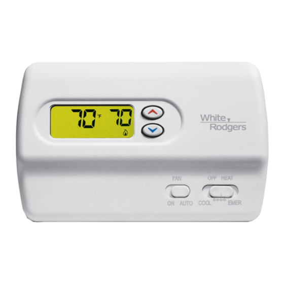
Your new White-Rodgers Digital Heat Pump Thermostat
uses the technology of a solid-state microcomputer to
provide precise temperature control. This thermostat of-
fers you the flexibility to set heating and cooling tempera-
tures that fit your needs.
Features:
• Simultaneous heat and cool temperature storage
• LCD continuously displays set point and room tem-
perature
This thermostat is intended for use with a 24-volt system;
do not use this thermostat with a millivolt or line voltage
system. If in doubt about whether your wiring is millivolt,
line, or low voltage, have it inspected by a qualified
heating and air conditioning contractor or electrician.
Do not exceed the specification ratings.
All wiring must conform to local and national electrical
codes and ordinances.
This control is a precision instrument, and should be
handled carefully. Rough handling or distorting compo-
nents could cause the control to malfunction.
ELECTRICAL DATA
Electrical Rating:
20 to 30 VAC 50/60 Hz. or D.C.
0.05 to 1.5 Amps (Load per terminal)
1.5 Amps Maximum Total Load (All terminals
combined)
THERMAL DATA
Setpoint Temperature Range:
45 F to 90 F (7 C to 32 C)
Operating Ambient Temperature Range:
32 F to 105 F
WHITE-RODGERS DIVISION
EMERSON ELECTRIC CO.
9797 REAVIS ROAD
ST. LOUIS, MISSOURI 63123-5398
Non-Programmable Electronic Digital
OPERATION INSTRUCTIONS
• F/ C convertibility
• Temperature range 45 to 90 F
• Eight terminals for single or two-transformer systems
• O/B terminal for heat pump systems
• Armchair Demonstration Capability
To prevent electrical shock and/or equipment
damage disconnect electric power to system at
main fuse or circuit breaker box until installation
is complete.
Do not use on circuits exceeding specified volt-
age. Higher voltage will damage control and
could cause shock or fire hazard.
Do not short out terminals on gas valve or pri-
mary control to test. Short or incorrect wiring will
damage thermostat and could cause personal
injury and/or property damage.
Operating Humidity Range:
0 to 90% RH (non-condensing)
Shipping Temperature Range:
-40 F to 150 F
APPLICATIONS
For use with:
• Heat pump systems with up to two stages heat,
one stage cool
DO NOT USE WITH:
• Millivolt systems
• Systems exceeding 30 VAC and 1.5 amps
• 3-wire zoned hydronic heating systems
Printed in U.S.A.
1F89-11
Heat Pump Thermostat
INSTALLATION AND
DESCRIPTION
PRECAUTIONS
CAUTION
!
WARNING
!
SPECIFICATIONS
PART NO. 37-5741A
Replaces 37-5612B
9636
Advertisement

Related Manuals for White Rodgers 1F89-11


Summary of Contents for White Rodgers 1F89-11
-
Page 1: Specifications
Operating Ambient Temperature Range: 32 F to 105 F WHITE-RODGERS DIVISION EMERSON ELECTRIC CO. 9797 REAVIS ROAD ST. LOUIS, MISSOURI 63123-5398 1F89-11 Non-Programmable Electronic Digital Heat Pump Thermostat INSTALLATION AND OPERATION INSTRUCTIONS • F/ C convertibility • Temperature range 45 to 90 F •... -
Page 2: Installation
INSTALLATION REMOVE OLD THERMOSTAT 1. Shut off electricity at the main fuse box until installation is complete. Ensure that electrical power is discon- nected. 2. Remove the front cover of the old thermostat. With wires still attached, remove wall plate from the wall. If the old thermostat has a wall mounting plate, remove the thermostat and the wall mounting plate as an assembly. -
Page 3: Wiring Diagrams
NOTE The following wiring diagrams show typical terminal identification and wiring. For proper installation, refer to Changeover Relay* Compressor Contactor * Changeover Relay is energized in COOL when O/B switch is in the “O” position Changeover Relay is energized in HEAT when O/B switch is in the “B” position Figure 3. -
Page 4: Check Thermostat Operation
ADJUSTABLE ANTICIPATION The first stage has anticipation that can be set to 2.5 or 4 cycles per hour for heating or cooling. The second stage heat has a fixed anticipation. To change the first stage anticipation in the HEAT mode, place the SYSTEM switch in the OFF position. -
Page 5: Operation
Before you begin operating your thermostat, you should be familiar with its features and with the display and the location and operation of the thermostat buttons. Your thermostat consists of two parts: the thermostat cover and the base. To remove the cover, gently pull it straight out from the base.