Table of Contents
Advertisement
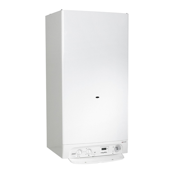
Riva
Riva
PLUS COMBI
WALL HUNG GAS BOILER FOR
CENTRAL HEATING SUPPLY
Please Read Instructions Carefully
Save for Future Reference
WARNING: If the information in this manual is not followed
exactly, a fi re or explosion may result causing property dam-
age, personal injury or loss of life.
—
Do not store or use gasoline or other fl ammable vapors and liquids
in the vicinity of this or any other appliance.
—
WHAT TO DO IF YOU SMELL GAS
•
Do not try to light any appliance.
•
Do not touch any electric switch; do not use any phone in your
building.
•
Immediately call your gas supplier from a neighbor's phone. Fol-
low the gas supplier's instructions.
•
If you can not reach your gas supplier call the fi re department.
—
Installation and service must be performed by a qualifi ed installer,
service agency or the gas supplier.
MANUEL RIVA COMBI - REV A
Advertisement
Table of Contents

Related Manuals for Biasi Riva Plus Combi


Summary of Contents for Biasi Riva Plus Combi
- Page 1 Riva Riva PLUS COMBI WALL HUNG GAS BOILER FOR CENTRAL HEATING SUPPLY Please Read Instructions Carefully Save for Future Reference WARNING: If the information in this manual is not followed exactly, a fi re or explosion may result causing property dam- age, personal injury or loss of life.
- Page 2 CSA 4.9 and is CSA compliant. This Riva Plus Combi has a 2 year warranty, a copy of which is provided with the boiler. Please be sure to return the warranty registration card as the warranty will be void without your boiler’s serial numbers (located on the ratings label affi...
-
Page 3: Table Of Contents
Connection to the Electricity Supply 12.2 Room Thermostat Connection 12.3 Relay Panel Control Connection 12.4 Zone Valve Microswitch Connection 12.5 Finishing 12.6 Circulator Sizing Circ. Cap. as a Function of Flow Rate 13.1 Expansion Vessel 13.2 Piping 31-34 RIVA PLUS COMBI MANUAL... -
Page 4: Warnings
Checking the press. in the exp.vassel 17.8 Visual Inspection of Appliance 17.9 Gas Pressures and Soundness 17.10 Cleanig the primary heat exchanger 17.11 Cleanig the domestic hot water exchanger 17.12 Condensate trap 17.13 Vent Part Spares 45-47 Installer Notes RIVA PLUS COMBI MANUAL... - Page 5 Caution: Do not use this boiler if any part has been under water. Immediately call a qualifi ed service technician to inspect the boiler and to replace any part of the control system and any gas control which has been under water. RIVA PLUS COMBI MANUAL...
- Page 6 If any of the symptoms of CO occur, or if any of the signs of carbon monoxide are present, VACATE THE PREMISES IMMEDIATELY AND CONTACT A QUALIFIED HEATING SERVICE COMPANY OR THE GAS COMPANY OR THE FIRE DEPARTMENT. ONLY QUALIFIED, LICENSED SERVICE CONTRACTORS SHOULD PERFORM WORK ON YOUR BIASI RIVA COMBI BOILER. RIVA PLUS COMBI MANUAL...
-
Page 7: Important Information
- B149 Installation Codes E. ANSI/ASME - CSD-1 The above codes are available from: National Fire Protection Association (NFPA) CSA International Battery March Park 8501 E. Pleasant Valley Road Quincy, Massachusetts, 02269 Cleveland, OH 44134-5575 http://www.nfpa.org http://www.csa-international.org RIVA PLUS COMBI MANUAL... -
Page 8: General Information
General Information The Riva Plus Combi is a high effi ciency condensing, wall mounted gas boiler which provides central heat. The boiler features a gas valve which modulates the energy input from 49476 BTU/h to 116008 BTU/h. The boiler is shipped fully assembled with the components listed on page 11. - Page 9 D.h.w. ΔT 30 K gal/h Nominal heat fl ow rate 116.0 D.h.w. ΔT 35 K gal/h (0/2000ft) D.h.w. ΔT 40 K gal/h Nominal heat fl ow rate 110.2 (2000/4500ft) Min Exhaust temperature °F Max Exhaust temperature °F RIVA PLUS COMBI MANUAL...
-
Page 10: Parts List
39. D.h.w fl ow limiter 19. Central heating pressure relief valve 40. Domestic hot water temp.probe NTC 20. Primary circuit fl ow switch 41. Domestic cold water inlet valve 21. Main circuit drain cock 42. D.h.w. outlet pipe 10 RIVA PLUS COMBI MANUAL... -
Page 11: Internal Piping And Parts List
Internal Piping & Parts List Note: Pressure Relief Valve (#19) should be piped to a drain or to the fl oor as lose as pos- sible to a drain. RIVA PLUS COMBI MANUAL... -
Page 12: Electric Diagrams
– red Label all wires prior to disconnection bu – blue wh - white gnye – green/yellow ye - yellow when servicing controls. Wiring errors can cause improper and dangerous operation. Verify proper operation after servicing. 12 RIVA PLUS COMBI MANUAL... -
Page 13: 5.1 Sequence Of Operation
5. Electric Diagrams Cont. 5.1 Sequence of Operation RIVA PLUS COMBI MANUAL... -
Page 14: Installation Location
Air Opening 0 to 12" Figure 6.2 When choosing an installation location insure the exhaust and intake pipes comply with NFPA 54. The drawing on the next page illustrates the restrictions on exhaust locations. 14 RIVA PLUS COMBI MANUAL... -
Page 15: Exhaust Pipe Location
The vent should not be situated so that the fl ue gases are directed towards brickwork,siding, or other construction , in such a manner that may cause damage from heat or condensate from the fl ue gases RIVA PLUS COMBI MANUAL... -
Page 16: Mounting Bracket
If you are using a separate pipe system drill holes marked B and C (ø 3.25”) shown below as well as on the paper template. Remove paper template and hang boiler on bracket. Figure 8.1 16 RIVA PLUS COMBI MANUAL... -
Page 17: Venting
If the Biasi Riva Plus Combi replaces a boiler that was attached to a common vent system, the common venting system is likely to be too large for proper venting of the appliances remaining connected to it. -
Page 18: Riva Plus Combi Manual
9. Venting Cont. • 18 RIVA PLUS COMBI MANUAL... -
Page 19: Choice Of Flue
Connect exhaust (inner) pipe to concentric elbow. • Connect intake (outer) pipe to concentric elbow. • Secure elbow to boiler using gasket and four screws provided. • Secure end cap on the intake pipe outside the house. RIVA PLUS COMBI MANUAL... - Page 20 • Attach each collar to the boiler with the gasket and screws provided. • Insert each elbow into its corresponding collar. • Connect each pipe to its corresponding elbow (as shown in the diagram). • Secure end cap on the intake and exhaust pipe outside the house 20 RIVA PLUS COMBI MANUAL...
- Page 21 • Slide one rubber wall trim piece on the pipe from inside and one from outside. • Attach each collar to the boiler with the gasket and screws provided. • Insert each elbow into its corresponding collar. • Connect each pipe to its corresponding elbow. RIVA PLUS COMBI MANUAL...
- Page 22 • Slide one rubber wall trim piece on the pipe from inside and one from outside. • Attach each collar to the boiler with the gasket and screws provided. • Insert each elbow into its corresponding collar. • Connect each pipe to its corresponding elbow. 22 RIVA PLUS COMBI MANUAL...
- Page 23 • Attach each collar to the boiler with the gasket and screws provided. • Insert each elbow into its corresponding collar. • Connect each pipe to its corresponding elbow (as shown in the diagram). • Secure end cap on the intake and exhaust pipe outside the house. RIVA PLUS COMBI MANUAL...
- Page 24 • Connect exhaust (inner) pipe to concentric elbow. • Connect intake (outer) pipe to concentric elbow. • Secure elbow to boiler using gasket and four screws provided. • Secure end cap on the intake pipe outside the house. 24 RIVA PLUS COMBI MANUAL...
-
Page 25: Pipe Connections
Pipe Connections The Riva Plus Combi is supplied with a 3/4” stainless steel gas pipe (A in fi gure 10.1), 2 - 3/4” copper pipe (C,D in fi gure 10.1), 2 - 1/2” (F,G in fi gure 10.1) located in a plastic bag in the boiler package. -
Page 26: Gas Pipe Connections
½ psi(3.5 kPa). WARNINGS DO NOT USE A FLAME FOR CHECKING GAS LEAKS. 26 RIVA PLUS COMBI MANUAL... -
Page 27: Electrical Connections/Wiring
15 AMP BREAKER Service Man's Switch Fire - O - Matic To fused spur isolation switch WARNING Power supply Note: Do not connect live wires to terminal block thermostat terminals 1-3. External controls terminal block Figure 12.5 RIVA PLUS COMBI MANUAL... -
Page 28: Room Thermostat Connection
Connect the dry contact switch to termi- Figure 12.8 nals 1 and 3 shown in Fig. 12.9. • When connecting any type of relay con- trol, the jumper J in Fig. 12.8 must be re- moved. 28 RIVA PLUS COMBI MANUAL... -
Page 29: Zone Valve Microswitch Connection
To the external control device To the fused spur isolation switch Figure 12.12 • Lock the cords in place with the fl exible cord clamps. • Replace the control panel reversing the steps on page 23. RIVA PLUS COMBI MANUAL... -
Page 30: Circulator Sizing
23 ft at most. For greater differences, increase the pre-load pressure in the C.h. expansion vessel (17 on page 11) and the system when cold, by 0.1 bar for additional 3.3 ft. For systems with volumes greater than 154l, an additional expansion vessel must be provided. 30 RIVA PLUS COMBI MANUAL... -
Page 31: Piping
In most circumstances 1 ¼” piping will be the best choice. When the boiler is piped in this way, the external circulator will not have any hydraulic effect on the Riva Plus Combi. This is essential to ensure that the fl ow switch will operate properly. Boiler... - Page 32 It is very important to use an hydraulic separator before secondary circulators. All external piping components are to be supplied by the installer. It is very important to use a hydraulic separator before secondary circulators. Figure 14.3 32 RIVA PLUS COMBI MANUAL...
- Page 33 14. Piping Cont. 14.2 Primary – Secondary Piping with Zone Valves: All external piping components are to be supplied by the installer. It is very important to use a hydraulic separator before secondary circulators. Figure 14.4 RIVA PLUS COMBI MANUAL...
- Page 34 14. Piping Cont. 14.3 Manifold Piping with Zone Valves (shown conn. to radiators): All external piping components are to be supplied by the installer. Figure 14.5 34 RIVA PLUS COMBI MANUAL...
-
Page 35: Commissioning
Turn on the electricity supply to the boiler, switching on the circuit breaker switch. The ap- pliance operation light A will fl ash every 4 seconds. • Turn the function selector B as in Fig. 15.3. The appliance operation light A will fl ash every 2 seconds. Figure 15.3 RIVA PLUS COMBI MANUAL... -
Page 36: Checking The Gas Pres. At The Burner
Section 2 on page 10 (gas pressures at the burner). • Check the maximum gas fl ow at the gas meter and compare the value indicated in the section 2 on page 10 (gas fl ow rate). 36 RIVA PLUS COMBI MANUAL... -
Page 37: Adjustment Of The Gas Pressure
(D on Figure 15.3). To reset the boiler turn the knob B (fi gure 15.3) on the 0 position and then press and release the boiler reset but- ton (C on Figure 15.3). RIVA PLUS COMBI MANUAL... -
Page 38: Checking The Burner Ignition
Adjust the gas pressure at the burner to the value according to the useful c.h. output wanted (Tab. 15.1). • Reassemble the service panel. • Close the gas valve outlet pressure test point 15 (fi gure 15.5). • Reassemble the front pannel of the case. 38 RIVA PLUS COMBI MANUAL... -
Page 39: Labels Placement
All the labels supplied with the boiler are numbered for reference. According to Figure 15.10 place all the labels on the boiler. Use label numbered as 1 (already installed in the front panel) to begin the placement in the correct way. RIVA PLUS COMBI MANUAL... -
Page 40: Instructing The User
2.23 2.46 2.69 2.91 3.14 3.36 ft³/h 5.77 6.56 7.31 8.07 8.82 9.54 10.30 11.02 1060 1270 1500 1740 2000 2270 inwc. 1.45 1.69 2.25 3.21 4.34 5.62 7.06 8.95 Propane Kg/h lb/h Table 15.1 40 RIVA PLUS COMBI MANUAL... -
Page 41: Gas Conversion
Loosen the screws D and remove the ser- sion kit) indicating the type of gas, and the vice panel (fi gure 16.2) gas pressures to which the appliance has been set. • Reassemble the front and side panels of the case. RIVA PLUS COMBI MANUAL... -
Page 42: Annual Maintenance
Open the central heating drain cock (F in Fig. 17.3). • Empty the c.h. system. • Close the central heating drain cock (F in Fig. 17.3). • Open the pressure reducing automatic fi ll valve (28 on Section 4) Figure 17.3 42 RIVA PLUS COMBI MANUAL... -
Page 43: Checking The Combustion Fan
Reinstall the elbow onto the horizontal run of the pipe fi rst by simply pushing the parts together. • Push the vent adapter down onto the top of the boiler and reinstall the four Phillips head screws. RIVA PLUS COMBI MANUAL... -
Page 44: Visual Inspection Of Appliance
• Disconnect the wirings from the trap. • Reassemble carrying out the removal op- erations in reverse order. The trap should be serviced once a year dur- ing the annual service. Figure 17.6 44 RIVA PLUS COMBI MANUAL... -
Page 45: Vent Part Spares
Vent Part Spares Figure 18.1 Description Order Number Twin pipe kit 10999.0393.0 RIVA PLUS COMBI MANUAL... - Page 46 18. Vent Part Cont. Figure 18.2 Description Order Number Coaxial fl ue kit 10999.0387.0 46 RIVA PLUS COMBI MANUAL...
- Page 47 18. Vent Part Cont. Figure 18.3 Part Description Order Number Coaxial fl ue kit 10999.0387.0 For any spare parts, please contact QHT Inc. at 800-501-7697. RIVA PLUS COMBI MANUAL...
-
Page 48: Installer Notes
Original Purchaser: ________________________ ___________________________ ________________________ ___________________________ ________________________ ___________________________ _______________________________________________________________________ Performance Tests: GROSS STACK TEMPERATURE __________________ ROOM TEMPERATURE (AMBIENT) ________________ NET STACK TEMPERATURE _____________________ __________________ ___________________ SMOKE READING ___________________ COMBUSTION EFFICIENCY _________________ COMMENTS ___________________________________________________________ _______________________________________________________________________ _______________________________________________________________________ 48 RIVA PLUS COMBI MANUAL... - Page 49 RIVA PLUS COMBI MANUAL...
- Page 50 50 RIVA PLUS COMBI MANUAL...
- Page 51 RIVA PLUS COMBI MANUAL...
- Page 52 17962.1481.0 2508 (52A4)USA...