
Related Manuals for Regency MX Excel


Summary of Contents for Regency MX Excel
- Page 1 Style that revolves around you. • C • EILING WNER'S ANUAL • MX E • XCEL REVISED NOVEMBER 2007 WARNING: Read and follow these instructions carefully and be mindful of all warnings shown throughout.
- Page 2 & O ENERAL NSTALLATION PERATION NSTRUCTIONS MPORTANT AFEGUARDS 1. To ensure the success of the installation, be sure to read the instructions and review the diagrams thoroughly before beginning. 2. To avoid possible electric shock, be sure electricity is turned off at the main power box before wiring. All electrical connections must be made in accordance with local codes, ordinances and/or the National Electric Code.
-
Page 3: Important Safety Precautions
MPORTANT AFETY RECAUTIONS Thank you for choosing a Regency Ceiling Fan. You have chosen the best! Your new ceiling fan has been designed to provide many years of service and enjoyment. Warnings: • Disconnect power by removing fuse or turning off circuit breaker before installing the fan and/or optional lighting. -
Page 4: Unpacking Your Fan
NPACKING 1. Unpack your fan and check the contents. Do not discard the carton. If warranty replacement or repair is ever necessary, the fan should be returned in original packing. Remove all parts and hardware. Do not lay motor housing on its side, or the decorative housing may shift, be bent or damaged. 2. -
Page 5: Installing The Mounting Bracket
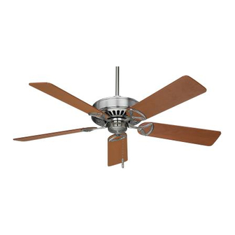
REPARATION Parts identification on assembled fan Canopy Collar Downrod Cover Blade Motor Housing Detachable Blade Switch Housing Pull Chain REPARATION Verify you have all parts before beginning the installation. Check foam insert closely for missing parts. Remove motor from packing. To avoid damage to finish, assemble motor on soft padded surface or use the original foam inset in motor box. - Page 6 NSTALLING NSTALLATION This fan has three installation options: HUGGER MOUNTING 3˝ DOWNROD MOUNTING The 3˝ DOWNROD or HUGGER methods are preferred if maximum headroom is required. Blades will be approximately 8-10˝ from the ceiling. Airflow will be reduced when the fan is installed using the 3˝ downrod or hugger options. 6˝...
- Page 7 NSTALLING THE UGGER TYLE #1: H NSTALLATION PTION UGGER TYLE OUNTING NOTE: The S hook is to be used for hugger style mounting. 1. Remove the plastic trim ring from the canopy to expose the 6 mounting holes. The downrod, ball and cotter pin will not be used for this mounting (Fig.
- Page 8 NSTALLING THE AN WITH A OWNROD 1. Carefully support fan body (motor) in its styrofoam packing with the mounting collar (where the wires come out) facing upward. Select the 3˝ or 6˝ (or optional extension) downrod you wish to use. 2.
- Page 9 NSTALLING THE AN WITH A OWNROD 1. Lift ball/downrod/fan into hanger bracket opening. NOTE: The tab opposite hanger bracket opening should fit in slot on ball (Fig. 3). 2. Make wire connections, (refer to section titled “Electrical Connections”). 3. Slide canopy up and fasten to hanger bracket with 4 screws provided. Fig.
-
Page 10: Electrical Connections
LECTRICAL ONNECTIONS Be sure electricity is turned off at the main power box before wiring LECTRICAL ONNECTIONS 1. Four wires are connected to the fan. Black – this is the “hot” power to run fan. White – this is the “common” power to run fan and light. Blue –... -
Page 11: Blade Attachment
LADE TTACHMENT LADE TTACHMENT 1. Place fiber washer on screw. Insert this assembly through the blade and start the screw into the blade arm. Repeat this procedure without tightening the screw until all 3 screws have been started into the blade arm (Fig. 4). NOTE: Fans that have painted finishes are packed with gaskets that can be used between the blade arm and blade to help prevent a clicking noise that may develop if blade screws loosen over time. - Page 12 4. Attach the switch housing to the switch housing hub. Be sure to align the opening on the edge of switch housing hub with reverse switch. 5. Align the side screws with keyhole slots on edge of switch housing and tighten the side screws. 6. Turn the power on. Your Regency Ceiling Fan is now ready to enjoy! Fig. 6...
-
Page 13: Operation
PERATION Turn on the power and check operation of the fan. The fan is controlled by the use of the fan speed pull chain as follows: one pull = high speed two pulls = medium speed three pulls = low speed four pulls = off For proper functions, ensure that the fan speed pull chain is pulled down fully and released each time. -
Page 14: Care And Cleaning
HANK YOU FOR PURCHASING A EGENCY EILING Write to us at: Regency Ceiling Fans P.O. Box 730 Fenton, MO 63026 Visit us on the Web at: www.regencyfan.com 5/04 Regency Ceiling Fans...