Table of Contents
Advertisement
Quick Links
Installer: Leave this manual with the appli-
ance.
Consumer: Retain this manual for future refer-
ence.
This appliance may be installed in an after-
market, permanently located, manufactured
home (USA only) or mobile home, where not
prohibited by state or local codes.
This appliance is only for use with the type of gas
indicated on the rating plate. This appliance is
not convertible for use with other gases, unless
a certified kit is used.
WARNING: If not installed, operated and
maintained in accordance with the manufactur-
er's instructions, this product could expose you
to substances in fuel or from fuel combustion
which can cause death or serious illness.
INSTALLATION INSTRUCTIONS
OWNER'S MANUAL
AND
FAN TYPE
DIRECT VENT
WALL FURNACE
MODEL
DV-55IP
WARNING: If the information in these instruc-
tions are not followed exactly, a fire or explosion
may result causing property damage, personal
injury or loss of life.
— Do not store or use gasoline or other flamma-
ble vapors and liquids in the vicinity of this or
any other appliance.
— WHAT TO DO IF YOU SMELL GAS
•
Do not try to light any appliance.
•
Do not touch any electrical switch; do not
use any phone in your building.
•
Immediately call your gas supplier from a
neighbor's phone. Follow the gas suppli-
er's instructions.
•
If you cannot reach your gas supplier, call
the fire department.
— Installation and service must be performed by
a qualified installer, service agency or the gas
supplier.
Page 1
Advertisement
Table of Contents
Troubleshooting

Related Manuals for Empire Heating Systems DV-55IP


Summary of Contents for Empire Heating Systems DV-55IP
-
Page 1: Installation Instructions
OWNER'S MANUAL FAN TYPE DIRECT VENT WALL FURNACE MODEL DV-55IP Installer: Leave this manual with the appli- WARNING: If the information in these instruc- ance. tions are not followed exactly, a fire or explosion Consumer: Retain this manual for future refer- may result causing property damage, personal ence. -
Page 2: Table Of Contents
TABLE OF CONTENTS SECTION PAGE Important Safety Information ........................3 Safety Information for Users of LP Gas ......................4 Requirements for Massachusetts ........................5 Introduction ..............................6 Specifications ...............................6 Gas Supply ............................... 7-8 Clearances ..............................8 Installation Instructions .......................... 9-11 Lighting Instructions ..........................12 Pilot Flame Characteristics ........................13 Main Burner Flame Characteristics ......................13 Wiring ................................14 Service and Maintenance Suggestions .................... -
Page 3: Important Safety Information
IMPORTANT SAFETY INFORMATION THIS IS A HEATING APPLIANCE DO NOT OPERATE THIS APPLIANCE WITHOUT FRONT PANEL INSTALLED. • Due to high temperatures the appliance should be located excessive lint from carpeting, bedding materials, etc. It is out of traffic and away from furniture and draperies. imperative that control compartments, burners and circu- lating air passageways of the appliance be kept clean. -
Page 4: Safety Information For Users Of Lp Gas
SAFETY INFORMATION FOR USERS OF LP-GAS Propane (LP-Gas) is a flammable gas which can cause fires by point with the members of your household. Someday when and explosions. In its natural state, propane is odorless and there may not be a minute to lose, everyone's safety will depend colorless. -
Page 5: Requirements For Massachusetts
REQUIREMENTS FOR MASSACHUSETTS For all side wall horizontally vented gas fueled equipment 3. SIGNAGE. A metal or plastic identification plate shall be installed in every dwelling, building or structure used in permanently mounted to the exterior of the building at a whole or in part for residential purposes, including those minimum height of eight (8) feet above grade directly in owned or operated by the Commonwealth and where the... -
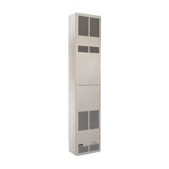
Page 6: Introduction
3.5" w.c. (.871kPa) to 2.8" w.c. (.697kPa) for Natural Gas and from depth of the appliance. 10.0" w.c. (2.49kPa) to 8.0" w.c. (1.992kPa) for Propane Gas. SPECIFICATIONS Model DV-55IP Input BTU/HR 55,000 Height 82 3/8" Width 16"... -
Page 7: Gas Supply
GAS SUPPLY Locating Gas Supply A manual main gas cock should be located in the vicinity of The gas line can enter the unit either through the floor or outside the unit. Where none exists, or where its size or location is not wall. -
Page 8: Clearances
Checking Manifold Pressure Both Propane and Natural gas valves have a built-in pressure regulator in the gas valve. Natural gas models will have a mani- fold pressure of approximately 3.5" w.c. at the valve outlet with the inlet pressure to the valve from a minimum of 5.0" w.c. for the purpose of input adjustment to a maximum of 7.0"... -
Page 9: Installation Instructions
INSTALLATION INSTRUCTIONS Locating Wall Opening The furnace is to be located on an outside wall. Locate wall studs so that wall opening will be located between wall studs. The furnace is 16 inches in width and normal 16 inches on center studs will not allow the furnace to be recessed into the wall unless a stud is repositioned. - Page 10 1. Attach 6" diameter air inlet tube onto the collar of air drop assembly. Be sure 6" diameter air inlet tube is placed as far as possible onto the collar of the air drop assembly. Mark the 6" diameter air inlet tube 1/2" beyond the outside wall. Remove 6"...
- Page 11 INSTALLATION INSTRUCTIONS (continued) Installing a Vent Near a Window Ledge, Warning: When vinyl siding vent kit, DV-822 or 2" x 4" Other Type of Projection or on Siding (vinyl, aluminum, etc.) framing is added to an existing installation (furnace is Direct vent furnaces are designed to be installed on a uniform installed) do not attempt to add sections of pipe to the flue outside wall.
-
Page 12: Lighting Instructions
LIGHTING INSTRUCTIONS FOR YOUR SAFETY READ BEFORE OPERATING WARNING: If you do not follow these instructions exactly, a fire or explosion may result causing property damage, personal injury or loss of life. A. This appliance is equipped with an ignition device which •... -
Page 13: Pilot Flame Characteristics
PILOT FLAME CHARACTERISTICS The pilot flame (Figure 11) going to the spark must be large enough to completely cover the sparking area. With the proper flame, only 2 or 3 sparks will occur. More sparks indicate a small pilot flame and no ignition with spark stopping after approximately 90 seconds generally means not enough flame. -
Page 14: Wiring
WIRING Wiring The appliance, when installed, must be electrically grounded in accordance with local codes or, in the absence of local codes, with the National Electrical Code, ANSI/NFPA 70 or Canadian Electrical Code, CSA C22.1, if an external electrical source is utilized. This appliance is equipped with a three-prong [grounding] plug for your protection against shock hazard and should be plugged directly into a properly grounded three-prong receptacle. -
Page 15: Service And Maintenance Suggestions
SERVICE & MAINTENANCE SUGGESTIONS GENERAL: All furnaces have been fire-tested to check for proper 4. Any time work is done on the system. operation. This includes, main burner flame, pilot flame, fan operation, fan STEP 1: Perform Visual Inspection. control, limit control and automatic valve operation. If the furnace fails to A. - Page 16 TRIAL FOR IGNITION The control system must be reset by setting the thermostat below room Pilot Ignition temperature for one minute or by turning off power to the module for Following call for heat (system start on S8600H), the module energizes the one minute.
-
Page 17: Troubleshooting
TROUBLESHOOTING Important WARNING 1. The following service procedures are provided as a general When performing the following steps, do not touch stripped end guide. of jumper or SPARK terminal. The ignition circuit generates 2. Meter readings between gas control and ignition module must 13,000 volts at 25 pf load and electrical shock can result. - Page 18 TROUBLESHOOTING Page 18 12432-13-1008...
-
Page 19: Troubleshooting
TROUBLESHOOTING Green LED Status Codes Green LED Flash Code (X + Y) Indicates Next System Action Recommended Service Action No “Call for Heat” Not applicable None Flash Fast Startup-Flame sense calibration Not applicable None Heart Beat Normal operation Not applicable None Recycle Initiate new trial for ignition. -
Page 20: How To Order Repair Parts
PARTS LIST PLEASE NOTE: When ordering parts, it is very important that part number and description of part coincide. Index Part Index Part Number Description Number Description 11762 Outer Casing Top 712098 Gasket for Observation Hole Cover 632024 Motor Mount (Four Required) DV-781 Lighting Hole Cover w/Mica 11764... -
Page 21: Parts View
PARTS VIEW 12432-13-1008 Page 21... -
Page 22: Service Notes
SERVICE NOTES Page 22 12432-13-1008... -
Page 23: Service Notes
SERVICE NOTES 12432-13-1008 Page 23... - Page 24 Empire Comfort Systems Inc. EMPIRE EMPIRE 918 Freeburg Ave. Belleville, IL 62220 If you have a general question about our products, please e-mail us at info@empirecomfort.com. If you have a service or repair question, please contact your dealer. Comfort Systems www.empirecomfort.com Page 24 12432-13-1008...