
Related Manuals for SMC Networks EZ Switch SMCGS1601P


Summary of Contents for SMC Networks EZ Switch SMCGS1601P
-
Page 1: User Guide
USER GUIDE EZ Switch 10/100/1000 16-Port Unmanaged Gigabit Ethernet PoE Switch SMCGS1601P... - Page 2 EZ Switch 10/100/1000 User Guide From SMC’s EZ line of low-cost workgroup LAN solutions No. 1, Creation Road III, Hsinchu Science Park, 30077, Taiwan, R.O.C. September 2012 TEL: +886 3 5638888 SMC-UG-0912-01 Fax: +886 3 6686111...
- Page 3 Information furnished by SMC Networks, Inc. (SMC) is believed to be accurate and reliable. However, no responsibility is assumed by SMC for its use, nor for any infringements of patents or other rights of third parties which may result from its use. No license is granted by implication or otherwise under any patent or patent rights of SMC.
-
Page 4: Warranty And Product Registration
ARRANTY AND RODUCT EGISTRATION To register SMC products and to review the detailed warranty statement, please refer to the Support Section of the SMC Website at http://www.smc.com. – –... -
Page 5: Compliances And Safety Statements
OMPLIANCES AND AFETY TATEMENTS EDERAL OMMUNICATION OMMISSION NTERFERENCE TATEMENT This equipment has been tested and found to comply with the limits for a Class A digital device, pursuant to part 15 of the FCC Rules. These limits are designed to provide reasonable protection against harmful interference in a residential installation. - Page 6 OMPLIANCES AND AFETY TATEMENTS CE M (EEC) ECLARATION OF ONFORMANCE FOR AFETY This information technology equipment complies with the requirements of the Council Directive 89/336/EEC on the Approximation of the laws of the Member States relating to Electromagnetic Compatibility and 73/23/EEC for electrical equipment used within certain voltage limits and the Amendment Directive 93/ 68/EEC.
- Page 7 OMPLIANCES AND AFETY TATEMENTS NDUSTRY ANADA LASS This digital apparatus does not exceed the Class A limits for radio noise emissions from digital apparatus as set out in the interference-causing equipment standard entitled “Digital Apparatus,” ICES-003 of the Department of Communications.Cet appareil numérique respecte les limites de bruits radioélectriques applicables aux appareils numériques de Classe A prescrites dans la norme sur le matériel brouilleur: “Appareils Numériques,”...
- Page 8 OMPLIANCES AND AFETY TATEMENTS AFETY RECAUTIONS Read the following information carefully before operating the device. Please follow the following precaution items to protect the device from risks and damage caused by fire and electric power: Use the power adapter that is included with the device package. ◆...
- Page 9 OMPLIANCES AND AFETY TATEMENTS surchauffe de l’appareil. Les orifices de ventilation de l’appareil sont conçus pour permettre la dissipation thermique et garantir le bon fonctionnement de l’appareil. Ne couvrez jamais ces orifices. Ne placez pas cet appareil à proximité d’une source de chaleur ou dans un ◆...
- Page 10 OMPLIANCES AND AFETY TATEMENTS Befolgen Sie die Hinweise im Benutzerhandbuch (bzw. in der Kurzanleitung) ◆ zum Anschluß des Gerätes an einen PC oder ein anderes Elektrogerät. Jegliche unzulässige Verbindung birgt die Gefahr von Stromschlägen und Brandgefahr. Platzieren Sie dieses Gerät nicht auf einer instabilen Oberfläche oder ◆...
- Page 11 OMPLIANCES AND AFETY TATEMENTS Leia atentamente as seguintes informações antes de utilizar o dispositivo. ◆ Respeite as seguintes indicações de segurança para proteger o dispositivo contra riscos e danos causados por fogo e energia eléctrica: Utilize o transformador incluído na embalagem do dispositivo. ◆...
- Page 12 OMPLIANCES AND AFETY TATEMENTS – 12 –...
-
Page 13: About This Guide
BOUT UIDE URPOSE This guide details the hardware features of the switch, including the physical and performance-related characteristics, and how to install the switch. UDIENCE The guide is intended for use by network administrators who are responsible for installing and setting up network equipment; consequently, it assumes a basic working knowledge of LANs (Local Area Networks). - Page 14 BOUT UIDE – 14 –...
-
Page 15: Table Of Contents
ONTENTS ARRANTY AND RODUCT EGISTRATION OMPLIANCES AND AFETY TATEMENTS BOUT UIDE ONTENTS NTRODUCTION Overview Features PoE Features IEEE 802.1p QoS ARDWARE ESCRIPTION Front Panel Port and System Status LEDs RJ-45 Ports Rear Panel AC Power Socket NSTALLING THE WITCH Package Contents Precautions Safety Requirements Location Requirements... - Page 16 ONTENTS Powering On Connecting Network Devices Cabling Guidelines Connecting to PCs, Servers, Hubs and Switches RODUCT PPLICATION Department/Workgroup PoE Switch Power over Ethernet Powered Devices ROUBLESHOOTING Diagnosing Switch Indicators The Power LED is Off The Link/Act LED is Off when a Device is Connected to the Corre- sponding Port Power and Cooling Problems Installation...
-
Page 17: Introduction
NTRODUCTION VERVIEW The EZ Switch 10/100 SMCGS1601P PoE switch provides 16 10/100/1000 Mbps auto-negotiating RJ-45 ports. Each port on the switch support auto MDI/MDI-X, which eliminates the need for crossover cables or uplink ports. The switch is plug-and-play; any port can be connected to a server, a hub, or a switch, using straight-through or crossover cable. -
Page 18: Poe Features
Overview EATURES The SMCGS1601P can provide up to 30 Watts of power to attached devices, such as VoIP phones, wireless access points, surveillance cameras, etc, all over existing Cat. 5 cables. The switch can deliver up to 30 Watts on 8 ports, or 15.4 Watts on 16 ports. - Page 19 Packets with priority tag 6 and 7 are assigned to the switch’s TC3 level ◆ queue. The SMCGS1601P switch uses Weighted Robin Round (WRR) for scheduling. The WRR queue-scheduling algorithm schedules all the queues in turn with every queue assured a certain service time. For both WFQ and WRR mode, the default weight values of TC0, TC1, TC2 and TC3 are 1:2:4:8.
- Page 20 | Introduction HAPTER Overview – 20 –...
-
Page 21: Description
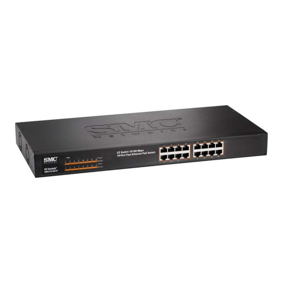
This chapter describes the front panel, rear panel, and LED indicators of the switch. RONT ANEL The front panel of SMCGS1601P consists of switch LED indicators, and 16 10/ 100/1000 Mbps RJ-45 ports. Figure 2: SMCGS1601P Switch Front Panel EZ Switch 10/100/1000Mbps... -
Page 22: Ports
Each port also supports IEEE 802.3x auto-negotiation of flow control, so the switch can automatically prevent port buffers from becoming saturated. ANEL The rear panel of the switch features a power socket. Figure 3: SMCGS1601P Switch Rear Panel 100-240VAC 50-60Hz 1A 100-240 VAC 50 / 60 Hz... -
Page 23: Installing The Switch
SMC distributor. Also be sure you have all the necessary tools and cabling before installing the switch. ACKAGE ONTENTS The following contents should be found in your package: One SMCGS1601P Switch ◆ One power cord ◆ This User Guide ◆... -
Page 24: Location Requirements
| Installing the Switch HAPTER Installation Take waterproof measures during storage, transportation and operation of ◆ the equipment. Use only the power cord provided with the switch. ◆ Make sure the voltage of the power supply meets the requirement of the ◆... -
Page 25: Desktop Installation
| Installing the Switch HAPTER Installation ESKTOP NSTALLATION To install the switch on the desktop, follow these steps: Set the switch on a flat surface strong enough to support the entire weight of the switch with all fittings. Remove the adhesive backing papers from the rubber feet. Turn the switch over and attach the supplied rubber feet to the recessed areas on the bottom at each corner of the switch. - Page 26 | Installing the Switch HAPTER Installation Figure 5: Attaching Brackets E Z S w it c h 1 0 /1 0 0 /1 1 6 -P o rt G ig a 0 0 0 M b b it E th e rn e t P o E S w it c h...
-
Page 27: Connecting To Ground
| Installing the Switch HAPTER Installation Use suitable screws (not provided) to secure the brackets to the rack, as illustrated in the following figure. Figure 6: Mounting the Switch E Z S w it c h 1 0 1 6 -P o /1 0 0 /1 rt G ig a 0 0 0 M b... -
Page 28: Powering On
OWERING The SMCGS1601P switch is powered by connecting to an AC power supply using a power cord. When powering on the switch, it automatically initializes and the LED indicators respond as follows: All of the LED indicators flash momentarily for one second, which represents a resetting of the system. -
Page 29: Connecting Network Devices
| Installing the Switch HAPTER Connecting Network Devices The Power LED indicator turns on green. ONNECTING ETWORK EVICES This switch is designed to be connected to 10, or 100 Mbps network cards in PCs and servers, as well as to other switches and hubs. ABLING UIDELINES The RJ-45 ports on the switch support automatic MDI/MDI-X pinout... - Page 30 | Installing the Switch HAPTER Connecting Network Devices – 30 –...
-
Page 31: Department/Workgroup Poe Switch
EPARTMENT ORKGROUP WITCH The SMCGS1601P provides 16 PoE port interfaces and can build a centrally- controlled IP phone system, IP camera system, or wireless AP group for the enterprise. Cameras can be installed around the company or campus for surveillance needs, or wireless APs can build a wireless roaming environment in the office. -
Page 32: Product Application
| Product Application HAPTER Power over Ethernet Powered Devices OWER OVER THERNET OWERED EVICES Table 2: Power over Ethernet Powered Devices Voice over IP phones Enterprises can install PoE VoIP phones, ATA and other Ethernet/ non-Ethernet end-devices connected to a central location where an un-interruptible power supply and power control system are installed. -
Page 33: A Troubleshooting
ROUBLESHOOTING IAGNOSING WITCH NDICATORS OWER Make sure the AC power cord is connected to the switch and power source ◆ properly. Make sure the power source is ON. ◆ FF WHEN A EVICE IS ONNECTED TO THE ORRESPONDING Make sure that the cable connectors are firmly plugged into the switch and ◆... -
Page 34: Installation
| Troubleshooting PPENDIX Installation NSTALLATION Verify that all system components have been properly installed. If one or more components appear to be malfunctioning (such as the power cord or network cabling), test them in an alternate environment where you are sure that all the other components are functioning properly. -
Page 35: Specifications
PECIFICATIONS HYSICAL HARACTERISTICS TANDARDS IEEE 802.3 10BASE-T IEEE 802.3u 100BASE-TX IEEE 802.3ab 1000BASE-TX OPOLOGY Star ROTOCOL CSMA/CD RANSFER Ethernet: 10 Mbps (half duplex) Ethernet: 20 Mbps (full duplex) Fast Ethernet: 100 Mbps (half duplex) Fast Ethernet: 200 Mbps (full duplex) Gigabit Ethernet :1000 Mbps (full duplex) ETWORK EDIA... - Page 36 | Specifications PPENDIX Physical Characteristics UMBER OF ORTS 16 10/100/1000 Mbps auto-negotiating RJ-45 ports INDICATORS System: PWR Ports: LNK/ACT, PoE In Use RANSFER ETHOD Store-and-Forward MAC A DDRESS EARNING Automatically learning, automatically aging RAME ILTER 10Mbps: 14880pps 100Mbps: 148800pps 1000Mbps: 1488000pps RAME ORWARD 10Mbps: 14880pps...
- Page 37 | Specifications PPENDIX Physical Characteristics HROUGHOUT 24 Mpps EATURES Supports IEEE 802.3af/at Supported Power to PD: 30W Total PoE Budget: 200W (Total Power: 240W) PoE Ports: 16 ( Ports 1-16) OWER UPPLY AC input : 100~240V, 50/60Hz DC output: DC 50V, 4.5A IMENSIONS 44.2 x 20.8 x 4.4 cm (17.4 x 8.2 x 1.73 in.) EIGHT...
- Page 38 | Specifications PPENDIX Physical Characteristics – 38 –...
- Page 40 SMC NETWORKS TECHNICAL SUPPORT From Singapore in English and (Mon.-Fri. 9AM to 5 PM) Tel: +65-63387667, Ext. 4 From U.S.A. and Canada (24 hours a day, 7 days a week) Tel: +1 (800) SMC-4-YOU/+1 (949) 679-8000 Fax: +1 (949) 679-1481...